2ATPH-JPPJPROTECT
JUGANU Ltd.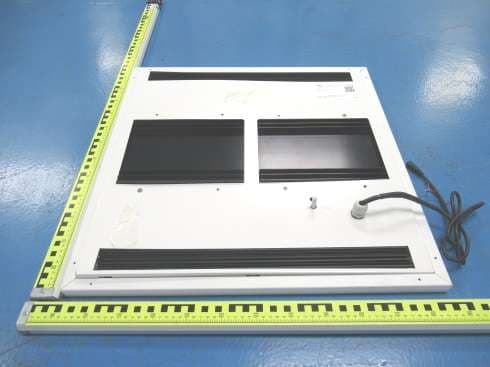
Click to zoom
Application Details
- Equipment Class
- CYY - Communications Receiver used w/Pt 15 Transmitter
- Date of Grant
- May 17, 2021
- Application Purpose
- Original Equipment
- Date of Application
- May 16, 2021
- Equipment Note
- JPROTECT
- Frequency Range
- 915.10000000 - 915.10000000
- Company
- JUGANU Ltd.
- Country
- Israel
Documents & Files
Document Text
Text extracted from the exhibit documents filed with the FCC. Open a document above to read the original.
Users Manual
Do not make or alter any open holes in the fixture enclosure of wiring or electrical components during J.Protect installation. • J.Protect panel should be installed by a certified licensed installer in accordance to local law. • A second person is required for the installation to support fixture weight. J. Protect is designed for indoor installation in accordance with the National Electrical Code and all applicable local codes. Do not use in areas of limited ventilation. 1. Do not install in case fixture is damaged. 2. Install on grid and allow a minimum 15mm/6” of clearance. 3. Before installation, turn power off. FOLLOW THESE INSTRUCTIONS CAREFULLY TO AVOID DAMAGE TO FIXTURE OR PERSONAL INJURY J.Protect Allegro – Panel J.Protect Allegro - LED Panel 60x60 / 2x2 Installation Guide CAUTION CAUTION CAUTION www.juganu.com Information provided is subject to change without notice. Please verify all details with Juganu. All values are typical values when measured under laboratory conditions, and Juganu makes no warranty or guarantee, expressed or implied, that such performance will be obtained under end-use conditions. J.Protect Panel Installation Guide July 2020 595 595 88 1. Remove ceiling tile or existing fixture • Turn power off before taking out existing fixture 2. Secure lamp to ceiling using supplied safety cables • 2 steel cables per fixture are attached • Safety wire: 2m / 1mm diameter steel wire with 10mm hook and a mechanical lock mechanism 3. Safely connect to AC power in accordance to diagram. 5. Align panel horizontally and lay in place. • Allow a min of 15cm / 6” clearance for ventilation 4. Tilt panel in a 45 o angle to insert into ceiling. AC GNE LINE NEUTRAL J.PROTECT Add Min 25cm / 10” min clearance www.juganu.com Information provided is subject to change without notice. Please verify all details with Juganu. All values are typical values when measured under laboratory conditions, and Juganu makes no warranty or guarantee, expressed or implied, that such performance will be obtained under end-use conditions. J.Protect Panel Installation Guide July 2020 Green/Yellow Blue Brown Do not cover with isolating materials Min of 15cm/6” Clearance J.Protect Allegro - LED Panel 60x60 / 2x2 Installation Guide This equipment has been tested and found to comply with the limits for a Class B digital device, pursuant to part 15 of the FCC Rules. These limits are designed to provide reasonable protection against harmful interference in a residential installation. This equipment generates, uses and can radiate radio frequency energy and, if not installed and used in accordance with the instructions, may cause harmful interference to radio communications. However, there is no guarantee that interference will not occur in a particular installation. If this equipment does cause harmful interference to radio or television reception, which can be determined by turning the equipment off and on, the user is encouraged to try to correct the interference by one or more of the following measures: • Reorient or relocate the receiving antenna. • Increase the separation between the equipment and receiver. • Connect the equipment into an outlet on a circuit different from that to which the receiver is connected. • Consult the dealer or an experienced radio/TV technician for help. Caution: Any changes or modifications to this device not explicitly approved by manufacturer could void your authority to operate this equipment. This device complies with part 15 of the FCC Rules. Operation is subject to the following two conditions: (1) This device may not cause harmful interference, and (2) this device must accept any interference received, including interference that may cause undesired operation.
Cover Letter(s)
JUGANU Ltd. 1 Yahadut Canada 1A, terminal center, building A, 2nd Floor, Or Yehuda, Israel. TEL: + 972-522790969 Series Models Description Federal Communications Commission Authorization and Evaluation Division 7435 Oakland Mills Road Columbia, MD 21046 To whom it may concern: Our product (Name: JPROTECT), Models number: proposed certification number FCC ID: 2ATPH-JPP. All the models have same electrical, PCB and BOM, only different in the product size and appearance. The receiver module is identical. For more information, please refer to the user’s manual. Sincerely, Signature: Print: David Davidov Title: HW Manager Phone number: +972-522790969 Email: [email protected]
Cover Letter(s)
5/11/2021 Equipment Autorisation Division Federal Communications Commission 7435 Oakland Mills Road Columbia, MD 21046 FCC ID: 2ATPH-JPP Product Name: JPROTECT Request for Confidentiality Pursuant to Sections 0.457 and 0.459 of the commissions rules, we hereby request that the following documents be held confidential: Schematics Long-term confidential Block diagram Long-term confidential Operation description Long-term confidential These materials contain trade secrets and proprietary information and are not customarily released to the public. The public disclosure of this information might be harmful to the company and provide unjustified benefits to our competitors. Signature: Name David Davidov Position HW Manger Company Name JUGANU Ltd. Address 1 Yahadut Canada 1A, terminal center, building A, 2nd Floor, Or Yehuda, Israel Tel +972-522790969 Fax +972-3-531-0113 Email [email protected]
External Photos
FCC ID: 2ATPH-JPP FCC ID: 2ATPH-JPP FCC ID: 2ATPH-JPP
ID Label/Location Info
4.5cm 2.5cm Label Location FCC ID: 2ATPH-JPP JUGANU Ltd. Product name: JPROTECT Model No.: JPP-C-R-TU-B-30-D03-P1 This device complies with Part 15 of the FCC Rules. Operation is subject to the following two conditions: (1) this device may not cause harmful interference, and (2) this device must accept any interference received, including interference that may cause undesired operation.
Internal Photos
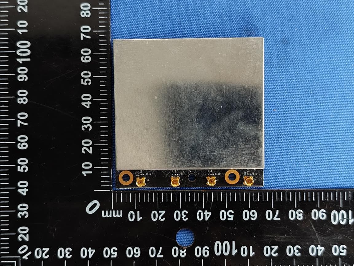
FCC ID: 2ATPH-JPP FCC ID: 2ATPH-JPP FCC ID: 2ATPH-JPP FCC ID: 2ATPH-JPP FCC ID: 2ATPH-JPP FCC ID: 2ATPH-JPP FCC ID: 2ATPH-JPP FCC ID: 2ATPH-JPP FCC ID: 2ATPH-JPP FCC ID: 2ATPH-JPP
Test Report
FCC TEST REPORT FCC ID: 2ATPH-JPP On Behalf of JUGANU Ltd. JPROTECT Model No.: See model list Prepared for : JUGANU Ltd. Address : 1 Yahadut Canada 1A, terminal center, building A, 2nd Floor, Or Yehuda, Israel Prepared By : Shenzhen Alpha Product Testing Co., Ltd. Address : Building i, No.2, Lixin Road, Fuyong Street, Bao'an District, 518103, Shenzhen, Guangdong, China Report Number : A2104199-C01-R01 Date of Receipt : April 26, 2021 Date of Test : April 26, 2021– April 29, 2021 Date of Report : May 6, 2021 Version Number : V0 Page 2 of 40 Report No.: A2104199-C01-R01 TABLE OF CONTENTS Description Page 1. General Information ........................................................................................................... 5 1.1. Description of Device (EUT) ...................................................................................... 5 1.2. Accessories of Device (EUT) ..................................................................................... 5 1.3. Tested Supporting System Details. ............................................................................. 6 1.4. Block Diagram of connection between EUT and simulators ...................................... 6 2. Summary of Standards and Results .................................................................................. 7 2.1. Description of Standards and Results ......................................................................... 7 2.2. Test Mode Description ................................................................................................ 8 2.3. Test Equipment List .................................................................................................... 9 2.4. Test Facility .............................................................................................................. 10 2.5. Measurement Uncertainty ......................................................................................... 10 3. Power Line Conducted Emission Test ............................................................................. 11 3.1. Test Limits ................................................................................................................ 11 3.2. Block Diagram of Test Setup .................................................................................... 11 3.3. Configuration of EUT on Test .................................................................................. 12 3.4. Operating Condition of EUT .................................................................................... 12 3.5. Test Procedure .......................................................................................................... 12 3.6. Test Results ............................................................................................................... 13 4. Radiated Emission Test ..................................................................................................... 16 4.1. Test Limit .................................................................................................................. 16 4.2. Block Diagram of Test Setup .................................................................................... 17 4.3. Configuration of EUT on Test .................................................................................. 18 4.4. Operating Condition of EUT .................................................................................... 18 4.5. Test Procedure .......................................................................................................... 18 4.6. Test Results ............................................................................................................... 19 5. Photograph ......................................................................................................................... 25 5.1. Photo of Radiated Emission Test (In Semi Anechoic Chamber) .............................. 25 5.2. Photo of Power Line Conducted ............................................................................... 26 6. Photos of the EUT .............................................................................................................. 27 Annex ......................................................................................................................................... 40 Page 3 of 40 Report No.: A2104199-C01-R01 TEST REPORT DECLARATION Applicant : JUGANU Ltd. Address : 1 Yahadut Canada 1A, terminal center, building A, 2nd Floor, Or Yehuda, Israel Manufacturer : JUGANU Ltd. Address : 1 Yahadut Canada 1A, terminal center, building A, 2nd Floor, Or Yehuda, Israel EUT Description : JPROTECT (A) Model No. : See model list (B) Trademark : Measurement Standard Used: FCC Rules and Regulations Part 15 Subpart B Class B, ANSI C63.4:2014 The device described above is tested by Shenzhen Alpha Product Testing Co., Ltd. to determine the maximum emission levels emanating from the device and the severe levels of the device can endure and its performance criterion. The test results are contained in this test report and Shenzhen Alpha Product Testing Co., Ltd. is assumed full responsibility for the accuracy and completeness of test. Also, this report shows that the EUT is technically compliant with the FCC Part 15 requirements. This report applies to above tested sample only. This report shall not be reproduced in parts without written approval of Shenzhen Alpha Product Testing Co., Ltd. Tested by (name + signature).............: Lucas Pang Project Engineer Approved by (name + signature).......: Simple Guan Project Manager Date of issue.............................: May 6, 2021 Page 4 of 40 Report No.: A2104199-C01-R01 Revision History Revision Issue Date Revisions Revised By V0 May 6, 2021 Initial released Issue Lucas Pang Page 5 of 40 Report No.: A2104199-C01-R01 1. General Information 1.1. Description of Device (EUT) Product Name : JPROTECT Model Number : See model list See model list. : All the mo…
Text truncated - open the document above for the full version.
Test Setup Photos
FCC ID: 2ATPH-JPP Radiated Emission FCC ID: 2ATPH-JPP Conducted Emission
Contact Information
Applicant
David Davidov(HW Manager)
Test Firm
Shenzhen Alpha Product Testing Co., LTD.Simple Guan
[email protected]+86 755 29766001-810
Technical Specifications
| # | Rule Parts | Frequency Range | Power Output |
|---|---|---|---|
| 1 | 15B | 915.1 MHz - 915.1 MHz | - |
Other Applications from JUGANU Ltd.
2ATPH-JS-WI-6
Mar 09, 2026RF PCBAs
Equipment Class
NII - Unlicensed National Information Infrastructure TX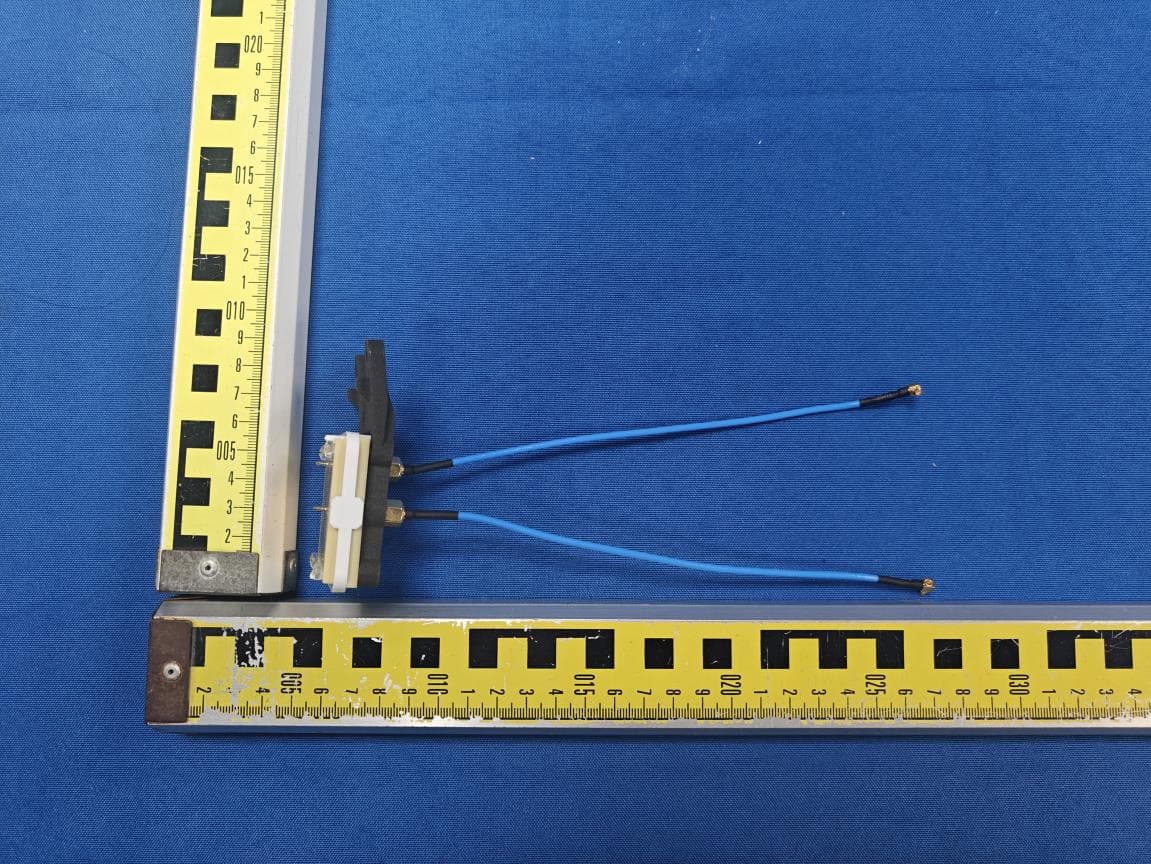
2ATPH-JS-WI-2-4
Mar 06, 2026RF PCBAs
Equipment Class
DTS - Digital Transmission System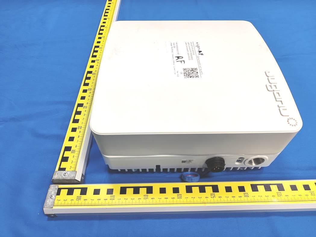
2ATPH-JNET2-OD
Jan 29, 2023CAP OUTDOOR
Equipment Class
NII - Unlicensed National Information Infrastructure TX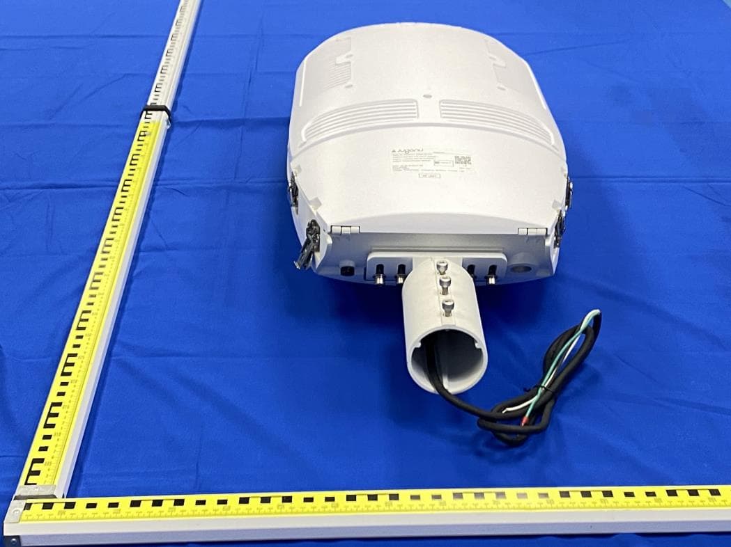
2ATPH-PHOENIX1
Jul 03, 2022Wireless us part
Equipment Class
NII - Unlicensed National Information Infrastructure TX
2ATPH-JNET1-915MHZ
Jun 22, 2020RF module
Equipment Class
DTS - Digital Transmission System