2ATPH-PHOENIX1Wireless us part
JUGANU Ltd.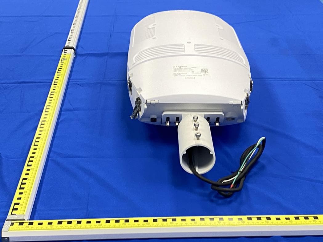
Click to zoom
Application Details
- Equipment Class
- NII - Unlicensed National Information Infrastructure TX
- Date of Grant
- Jul 03, 2022
- Application Purpose
- Original Equipment
- Date of Application
- Jul 02, 2022
- Equipment Note
- Wireless us part
- Frequency Range
- 5745.00000000 - 5825.00000000
- Company
- JUGANU Ltd.
- Country
- Israel
Documents & Files
Document Text
Text extracted from the exhibit documents filed with the FCC. Open a document above to read the original.
Users Manual
Phoenix 1 Installation Guide Phoenix 1 Installation Guide Juganu HQ 1 Yahadut Canada St., Or-Yehuda, Israel Tel.: + 972-3-5310031 [email protected] WWW.JUGANU.COM The Information provided herein is subject to change without prior notice by Juganu. Please verify all details with Juganu. All values are typical values when measured under normal laboratory conditions, and Juganu makes no warranties, expressed or implied, that such performance will be obtained under end-use conditions. JL-IG_Phoenix1 | Rev.03 2 Safety Instructions and Warnings DANGER - Risk of Shock - Disconnect Power before Installation FOLLOW THESE INSTRUCTIONS CAREFULLY TO AVOID DAMAGE TO FIXTURE AND PERSONAL INJURY - Installation must be performed by a certified licensed electrician in accordance with local law. - Make sure the AC power grid functions properly, otherwise the internal driver may be damaged. - Visually inspect the fixture for visible cracks, missing screws, or exposed electrical components. - In case of fault, please bring the fixture to an accredited Juganu laboratory for repair. Juganu has the right not to provide after-sales service if repair/maintenance was carried out by a non-licensed/certified body for its products. - The light fixture is designed for installation on a suitable Pole only. - Do not remove the label of the fixture. - Keep the light fixture away from extreme heat sources or flames. Do not make or alter any open holes in an enclosure of wiring or electrical components during installation. CAUTION Phoenix 1 Installation Guide Juganu HQ 1 Yahadut Canada St., Or-Yehuda, Israel Tel.: + 972-3-5310031 [email protected] WWW.JUGANU.COM The Information provided herein is subject to change without prior notice by Juganu. Please verify all details with Juganu. All values are typical values when measured under normal laboratory conditions, and Juganu makes no warranties, expressed or implied, that such performance will be obtained under end-use conditions. JL-IG_Phoenix1 | Rev.03 3 Introduction This guide shows how to install the Phoenix1 unit on a pole. The mounting arm is supplied by Juganu and supports a 51-60 mm diameter pole adaptor. Required Tools Metric Allen Key Hexagon Wrench Screwdriver Set Metric Open-end or combination wrench key Notes The Phoenix1 unit can be installed on a vertical or horizontal pole. The mounting arm orientation can be aligned to +/-15° Mounting arm (supplied by Juganu) Phoenix 1 Installation Guide Juganu HQ 1 Yahadut Canada St., Or-Yehuda, Israel Tel.: + 972-3-5310031 [email protected] WWW.JUGANU.COM The Information provided herein is subject to change without prior notice by Juganu. Please verify all details with Juganu. All values are typical values when measured under normal laboratory conditions, and Juganu makes no warranties, expressed or implied, that such performance will be obtained under end-use conditions. JL-IG_Phoenix1 | Rev.03 4 +/- 15° Horizontal Pole Installation +/- 15° Vertical Pole Installation Phoenix 1 Installation Guide Juganu HQ 1 Yahadut Canada St., Or-Yehuda, Israel Tel.: + 972-3-5310031 [email protected] WWW.JUGANU.COM The Information provided herein is subject to change without prior notice by Juganu. Please verify all details with Juganu. All values are typical values when measured under normal laboratory conditions, and Juganu makes no warranties, expressed or implied, that such performance will be obtained under end-use conditions. JL-IG_Phoenix1 | Rev.03 5 Installation Procedure for a Horizontal Pole 1. Insert the AC cable through the mounting arm. 2. Attach the mounting arm to the light fixture in the required orientation (+/- 15°) and tighten, using 4 M8 screws, a flat washer, and a helical washer. 3. Insert the AC wire protruding from the pole through the rear hole on the mounting adaptor. Mounting arm 4 x M8 1 2 Mounting adaptor Phoenix 1 Installation Guide Juganu HQ 1 Yahadut Canada St., Or-Yehuda, Israel Tel.: + 972-3-5310031 [email protected] WWW.JUGANU.COM The Information provided herein is subject to change without prior notice by Juganu. Please verify all details with Juganu. All values are typical values when measured under normal laboratory conditions, and Juganu makes no warranties, expressed or implied, that such performance will be obtained under end-use conditions. JL-IG_Phoenix1 | Rev.03 6 The adapter displayed is for illustration purposes only. You can use your own suitable adaptor. 4. Connect the mounting adapter by attaching the two (2) adapter parts to the pole and tighten, using four (4) M10 screws with M10 nuts, flat and helical washers. Phoenix 1 Installation Guide Juganu HQ 1 Yahadut Canada St., Or-Yehuda, Israel Tel.: + 972-3-5310031 [email protected] WWW.JUGANU.COM The Information provided herein is subject to change without prior notice by Juganu. Please verify all details with Juganu. All values are typical values when measured under normal laboratory conditions, and Juganu makes no warranties, expressed or implied, that such performance will be obtained under end-use conditions. JL-IG_Phoenix1 | Rev.03 7 5. Put the Light Fixture on the personnel platform’s floor. 6. Make an AC connection between the Light Fixture and the AC wire protruding from the mounting arm. 7. Insert the mounting arm of the Light Fixture into the adaptor arm and fasten using three (3) M8 bolts. Installation Procedure for a Vertical Pole Note: In the vertical orientation, a mounting adaptor is not required. 1. Insert the AC wire into the mounting adaptor. Phoenix 1 Installation Guide Juganu HQ 1 Yahadut Canada St., Or-Yehuda, Israel Tel.: + 972-3-5310031 [email protected] WWW.JUGANU.COM The Information provided herein is subject to change without prior notice by Juganu. Please verify all details with Juganu. All values are typical values when measured under normal laboratory conditions, and Juganu makes no warranties, expressed or implied, that such performance will be obtained under end-use conditions. JL-IG_Phoenix1 | Rev.03 8 2. M…
Text truncated - open the document above for the full version.
Cover Letter(s)
Juganu LTD Differences Description We Juganu LTD state: FCC ID: 2ATPH-PHOENIX1 Product name: Wireless us part Model:JLED-SL-120W-PHOENIX1-z-Dx, JLED-SL-120W-PHOENIX1-z-ND-P0-Dx-C1 (‘z’ denotes CCT, and can be ‘30’ for 3000K, ‘40’ for 4000K;‘x’ denotes beam angle of LED lens, can be ‘01’, ‘02’, ‘03’,...‘10’, such as ‘01’ for 60°, ‘02’ for 70°, ‘03’ for 80°,...‘10’ for 150°, 10° for step) Difference between both two series is ‘ND’ stand for dali function, only with different power supply, ‘EUM-150S150MG’ and ‘EUM-150S150BG’ with the same input and output ratings, not considered to effect the wireless function, and ‘z’, ‘x’ in series name denote difference CCT and beam angle of LED lens, are not considered to effect the wireless function, for all SCH, placement, hard version, soft version and functions are the same. Signature: 2022-06-24 Signatory Name David Davidov Position HW Manager Company Name Juganu LTD Address 1 Yahadut Canada 1A, terminal center, building A, 2nd Floor, Or Yehuda, Israel Tel +972-522790969 Email [email protected]
Cover Letter(s)
Juganu LTD June 24, 2022 Nemko Canada Inc 303 River Road Ottawa, Ontario, Canada K1V 1H2 Attn: Director of Certification Authority to Act as Agent On our behalf, I appoint Shenzhen Alpha Product Testing Co., Ltd. Address: Building i, No.2, Lixin Road, Fuyong Street, Bao’an District, 518103, Shenzhen, Guangdong, China Person: Mark Zhu (Name and address,person). to act as our agent in the preparation of this application for equipment certification. I certify that submitted documents properly describe the device or system for which equipment certification is sought. I also certify that each unit manufactured, imported or marketed, as defined in the Federal Communications Commission’s regulations will have affixed to it a label identical to that submitted for approval with this application. For instances where our authorized agent signs the application for certification on our behalf, I acknowledge that all responsibility for complying with the terms and conditions for certification, as specified by Nemko Canada Inc, still resides with Juganu LTD Address: 1 Yahadut Canada 1A, terminal center, building A, 2nd Floor, Or Yehuda, Israel ( applicant name and address). Signature: 2022-06-24 Name David Davidov Position HW Manager Company Name Shanghai Huace Navigation Technology Ltd. Address 599 Gaojing Road, Building D, Shanghai 201702, China Tel +972-522790969 Email [email protected]
Cover Letter(s)
Juganu LTD Office of Engineering Technology Federal Communications Commission 7435 Oakland Mills Road Columbia, MD 21046 Date: 2022-06-24 Subject; Request for Long Term Confidentiality FCC ID: 2ATPH-PHOENIX1 To Whom It May Concern, Pursuant to the provisions of the Commission’s rules Title 47 Sections §0.457 and §0.459, we are requesting the Commission to withhold the following attachment(s) as confidential documents from public disclosure indefinitely. These documents contain detailed system and equipment descriptions and are considered as proprietary information in operation of the equipment. The public disclosure of these documents might be harmful to our company and would give competitors an unfair advantage in the market. Schematic Diagram Block Diagram Operational Description It is our understanding that all measurement test reports, FCC ID label format and correspondence during the certification review process cannot be granted as confidential documents and this information will be available for public review once the grant of equipment authorization is issued. Sincerely, Signature: 2022-06-24 Name David Davidov Position HW Manager Company Name Juganu LTD Address 1 Yahadut Canada 1A, terminal center, building A, 2nd Floor, Or Yehuda, Israel Tel +972-522790969 Email [email protected]
External Photos
FCC ID: 2ATPH-PHOENIX1 EUT View EUT View FCC ID: 2ATPH-PHOENIX1 EUT View EUT View FCC ID: 2ATPH-PHOENIX1 EUT View EUT View
ID Label/Location Info
FCC ID: 2ATPH-PHOENIX1 10cm*5cm Label Location
Internal Photos
FCC ID: 2ATPH-PHOENIX1 EUT View EUT View FCC ID: 2ATPH-PHOENIX1 EUT View EUT View FCC ID: 2ATPH-PHOENIX1 EUT View EUT View 2.4GHz WiFi ANT 5GHz WiFi ANT FCC ID: 2ATPH-PHOENIX1 EUT View EUT View FCC ID: 2ATPH-PHOENIX1 EUT View EUT View FCC ID: 2ATPH-PHOENIX1 EUT View EUT View FCC ID: 2ATPH-PHOENIX1 EUT View EUT View FCC ID: 2ATPH-PHOENIX1 EUT View EUT View FCC ID: 2ATPH-PHOENIX1 EUT View EUT View FCC ID: 2ATPH-PHOENIX1 EUT View EUT View FCC ID: 2ATPH-PHOENIX1 EUT View EUT View FCC ID: 2ATPH-PHOENIX1 EUT View EUT View FCC ID: 2ATPH-PHOENIX1 EUT View FCC ID: 2ATPH-PHOENIX1 EUT View FCC ID: 2ATPH-PHOENIX1 EUT View EUT View FCC ID: 2ATPH-PHOENIX1 EUT View EUT View FCC ID: 2ATPH-PHOENIX1 EUT View EUT View 5GHz WiFi ANT FCC ID: 2ATPH-PHOENIX1 EUT View EUT View
Internal Photos
FCC ID: 2ATPH-PHOENIX1 EUT View EUT View FCC ID: 2ATPH-PHOENIX1 EUT View EUT View FCC ID: 2ATPH-PHOENIX1 EUT View EUT View FCC ID: 2ATPH-PHOENIX1 EUT View EUT View FCC ID: 2ATPH-PHOENIX1 EUT View EUT View FCC ID: 2ATPH-PHOENIX1 EUT View EUT View FCC ID: 2ATPH-PHOENIX1 EUT View EUT View FCC ID: 2ATPH-PHOENIX1 Photo of EUM-150S150BG EUT View EUT View
RF Exposure Info
FCC ID: 2ATPH-PHOENIX1 Prediction of MPE at a given distance According to 447498 D04 Interim General RF Exposure Guidance v01 The MPE-based test exemption condition is in terms of ERP, defined as the product of the maximum antenna gain and the delivered maximum time-averaged power. For this case, a RF source is an RF exempt device if its ERP (watts) is no more than a frequency-dependent value, as detailed tabular form as below. These limits have been derived based on the basic specifications on Maximum Permissible Exposure (MPE) considered for the FCC rules in § 1.1310(e)(1). “f” is in GHz Simultaneous Transmission with MPE-based Exemptions For these cases, a device with multiple RF sources transmitting simultaneously will be considered an RF exempt device if the condition of following Formula is satisfied. As this equipment: Distance=20cm f =2.462, f =5.795 So P th =3060mW Where: EIRP = Pm + Gi Pt=10 (EIRP/10) Pm = measured transmitter output power in dBm, Pt = transmitter output power in milliwatts, Gi = numeric gain of the transmitting antenna (unit-dBi) Ant gain Gi=2 dBi Pm1=28.29 dBm, Pm2=22.61 dBm, Pm3=21.76 dBm So Pt1=10 (28.29/10) mW =674.53 mW<3060mW Pt2=10 (22.61/10) mW =182.39 mW<3060mW Pt3=10 (21.76/10) mW =149.97 mW<3060mW Σ= Pt1/Pth + Pt2/ Pth + Pt3/ Pth =0.33<1 The MPE-based test exemption condition is meets the requirements.
Test Report
ALPHA's reports is using a digital certificate that is trusted on Adobe's official server. If there is no digital certificate or the digital certificate shows damaged in your report. Please do not accept the report. FCC TEST REPORT FCC ID: 2ATPH-PHOENIX1 On Behalf of Juganu LTD Wireless us part Model No.: JLED-SL-120W-PHOENIX1-z-Dx, JLED-SL-120W- PHOENIX1-z-ND-P0-Dx-C1 (‘z’ denotes CCT, and can be ‘30’ for 3000K, ‘40’ for 4000K;‘x’ denotes beam angle of LED lens, can be ‘01’, ‘02’, ‘03’,...‘10’, such as ‘01’ for 60°, ‘02’ for 70°, ‘03’ for 80°,...‘10’ for 150°, 10° for step) Prepared for : Juganu LTD Address : 1 Yahadut Canada 1A, terminal center, building A, 2nd Floor, Or Yehuda, Israel Prepared By : Shenzhen Alpha Product Testing Co., Ltd. Address : Building i, No.2, Lixin Road, Fuyong Street, Bao'an District, 518103, Shenzhen, Guangdong, China Report Number : A2205279-C01-R03 Date of Receipt : May 13, 2022 Date of Test : May 13, 2022 – June 16, 2022 Date of Report : June 17, 2022 Version Number : V0 Page 2 of 142 Report No.: A2205279-C01-R03 Contents Page 1 TEST SUMMARY ..................................................................................................................................... 5 1.1 MEASUREMENT UNCERTAINTY............................................................................................................. 5 2 GENERAL INFORMATION ...................................................................................................................... 6 2.1 GENERAL DESCRIPTION OF EUT ......................................................................................................... 6 2.2 TEST MODE ........................................................................................................................................ 7 2.3 TEST FACILITY .................................................................................................................................... 7 2.4 DESCRIPTION OF SUPPORT UNITS ....................................................................................................... 7 2.5 DEVIATION FROM STANDARDS ............................................................................................................. 7 2.6 ABNORMALITIES FROM STANDARD CONDITIONS.................................................................................... 7 2.7 OTHER INFORMATION REQUESTED BY THE CUSTOMER ......................................................................... 7 2.8 ADDITIONAL INSTRUCTIONS ................................................................................................................. 7 3 TEST INSTRUMENTS LIST ..................................................................................................................... 8 4 TEST RESULTS AND MEASUREMENT DATA .................................................................................... 10 4.1 ANTENNA REQUIREMENT: .................................................................................................................. 10 4.2 CONDUCTED EMISSIONS ................................................................................................................... 11 4.3 EMISSION BANDWIDTH AND 99% OCCUPIED BANDWIDTH .................................................................... 16 4.4 PEAK TRANSMIT POWER ................................................................................................................... 43 4.5 POWER SPECTRAL DENSITY .............................................................................................................. 45 4.6 BAND EDGE .................................................................................................................................... 108 4.7 RADIATED EMISSION ....................................................................................................................... 118 4.8 FREQUENCY STABILITY .................................................................................................................... 137 Page 3 of 142 Report No.: A2205279-C01-R03 TEST REPORT DECLARATION Applicant : Juganu LTD Address : 1 Yahadut Canada 1A, terminal center, building A, 2nd Floor, Or Yehuda, Israel Manufacturer : Juganu LTD Address : 1 Yahadut Canada 1A, terminal center, building A, 2nd Floor, Or Yehuda, Israel EUT Description : Wireless us part (A) Model No. : JLED-SL-120W-PHOENIX1-z-Dx, JLED-SL- 120W-PHOENIX1-z-ND-P0-Dx-C1 (‘z’ denotes CCT, and can be ‘30’ for 3000K, ‘40’ for 4000K;‘x’ denotes beam angle of LED lens, can be ‘01’, ‘02’, ‘03’,...‘10’, such as ‘01’ for 60°, ‘02’ for 70°, ‘03’ for 80°,...‘10’ for 150°, 10° for step) (B) Trademark : Measurement Standard Used: FCC Rules and Regulations Part 15 Subpart E RSS-247 Issue 2, ANSI C63.4:2014, ANSI C63.10:2013 The device described above is tested by Shenzhen Alpha Product Testing Co., Ltd. to determine the maximum emission levels emanating from the device. The maximum emission levels are compared to the FCC Part 15 Subpart E limits both conducted and radiated emissions. The test results are contained in this test report and Shenzhen Alpha Product Testing Co., Ltd. is assumed of full responsibility for the accuracy and completeness of these tests. After the test, our opinion is that EUT compliance with the requirement of the above standards. This report applies to above tested sample only. This report shall not be reproduced in parts without written approval of Shenzhen Alpha Product Testing Co., Ltd. Tested by (name + signature).........: Reak Yang Test Engineer Approved by (name + signature).......: Simple Guan Project Manager Date of issue...... .......................: June 17, 2022 Page 4 of 142 Report No.: A2205279-C01-R03 Revision History Revision Issue Date Revisions Revised By V0 June 17, 2022 Initial released Issue Reak Yang Page 5 of 142 Report No.: A2205279-C01-R03 1 Test Summary Test Item Section in CFR 47 Result Antenna requirement Section 15.203 Section 7.1.4 RSS-Gen Issue 5 PASS AC …
Text truncated - open the document above for the full version.
Test Report
Page 101 of 142 Report No.: A2205279-C01-R03 802.11ac(VHT40)_LCH_5755MHz_Ant2_NTNV 802.11ac(VHT40)_LCH_5755MHz_Ant3_NTNV Page 102 of 142 Report No.: A2205279-C01-R03 802.11ac(VHT40)_LCH_5755MHz_Ant4_NTNV 802.11ac(VHT40)_LCH_5755MHz_MIMO_NTNV Page 103 of 142 Report No.: A2205279-C01-R03 802.11ac(VHT40)_HCH_5795MHz_Ant1_NTNV 802.11ac(VHT40)_HCH_5795MHz_Ant2_NTNV Page 104 of 142 Report No.: A2205279-C01-R03 802.11ac(VHT40)_HCH_5795MHz_Ant3_NTNV 802.11ac(VHT40)_HCH_5795MHz_Ant4_NTNV Page 105 of 142 Report No.: A2205279-C01-R03 802.11ac(VHT40)_HCH_5795MHz_MIMO_NTNV 802.11ac(VHT80)_MCH_5775MHz_Ant1_NTNV Page 106 of 142 Report No.: A2205279-C01-R03 802.11ac(VHT80)_MCH_5775MHz_Ant2_NTNV 802.11ac(VHT80)_MCH_5775MHz_Ant3_NTNV Page 107 of 142 Report No.: A2205279-C01-R03 802.11ac(VHT80)_MCH_5775MHz_Ant4_NTNV 802.11ac(VHT80)_MCH_5775MHz_MIMO_NTNV Page 108 of 142 Report No.: A2205279-C01-R03 4.6 Band Edge Test Requirement: FCC Part15 E Section 15.407 and 15.205 Test Method: ANSI C63.10:2013 Test site: Measurement Distance: 3m (Semi-Anechoic Chamber) Receiver setup: Frequency Detector RBW VBW Remark 30MHz-1GHz Quasi-peak 100KHz 300KHz Quasi-peak Value Above 1GHz Peak 1MHz 3MHz Peak Value AV 1MHz 3MHz Average Value Limit: Frequency Limit (dBuV/m @3m) Remark 30MHz-88MHz 40.0 Quasi-peak Value 88MHz-216MHz 43.5 Quasi-peak Value 216MHz-960MHz 46.0 Quasi-peak Value 960MHz-1GHz 54.0 Quasi-peak Value Above 1GHz 54.0 Average Value 68.2 Peak Value Undesirable emission limits: (1) For transmitters operating in the 5.15-5.25 GHz band: all emissions outside of the 5.15-5.35 GHz band shall not exceed an EIRP of -27 dBm/MHz. (2) For transmitters operating in the 5.25-5.35 GHz band: all emissions outside of the 5.15-5.35 GHz band shall not exceed an EIRP of -27 dBm/MHz. Devices operating in the 5.25-5.35 GHz band that generate emissions in the 5.15-5.25 GHz band must meet all applicable technical requirements for operation in the 5.15-5.25 GHz band (including indoor use) or alternatively meet an out-of-band emission EIRP limit of -27 dBm/MHz in the 5.15-5.25 GHz band. (3) For transmitters operating in the 5.47-5.725 GHz band: all emissions outside of the 5.47-5.725 GHz band shall not exceed an EIRP of −27 dBm/MHz. Test Procedure: a. The EUT was placed on the top of a rotating table 1.5 m above the ground at a 3 meter camber. The table was rotated 360 degrees to determine the position of the highest radiation. b. The EUT was set 3 meters away from the interference-receiving antenna, which was mounted on the top of a variable-height antenna tower. c. The antenna height is varied from one meter to four meters above the ground to determine the maximum value of the field strength. Both horizontal and vertical polarizations of the antenna are set to make the measurement. d. For each suspected emission, the EUT was arranged to its worst case and then the antenna was tuned to heights from 1 meter to 4 meters and the rotable table was turned from 0 degrees to 360 degrees to find the maximum reading. e. The test-receiver system was set to Peak Detect Function and Specified Bandwidth with Maximum Hold Mode. f. If the emission level of the EUT in peak mode was 10dB lower than the limit specified, then testing could be stopped and the peak values of the EUT would be reported. Otherwise the emissions that did not have 10dB margin would be re-tested one by one using peak, quasi- peak or average method as specified and then reported in a data sheet. Test setup: Above 1GHz Page 109 of 142 Report No.: A2205279-C01-R03 Test Instruments: Refer to section 5.10 for details Test mode: Refer to section 5.3 for details Test results: Pass Remark: According to KDB 789033 D02 v02r01 section G) 1) (d), for For measurements above 1000 MHz @ 3m distance, the limit of field strength is computed as follows: E[dBuV/m] = EIRP[dBm] + 95.2, For example, if EIRP = -27dBm E[dBuV/m] = -27 + 95.2 = 68.2dBuV/m. Page 110 of 142 Report No.: A2205279-C01-R03 Measurement Data: Module 1 Band 1 802.11ac(VHT20) LCH 802.11ac(VHT40) LCH Page 111 of 142 Report No.: A2205279-C01-R03 802.11ac(VHT80) LCH Band4 802.11ac(VHT20) LCH Page 112 of 142 Report No.: A2205279-C01-R03 802.11ac(VHT20) HCH 802.11ac(VHT40) LCH Page 113 of 142 Report No.: A2205279-C01-R03 802.11ac(VHT40) HCH 802.11ac(VHT80) Page 114 of 142 Report No.: A2205279-C01-R03 Module 2 Band 1 802.11ac(VHT20) LCH 802.11ac(VHT40) LCH Page 115 of 142 Report No.: A2205279-C01-R03 802.11ac(VHT80) Band4 802.11ac(VHT20) LCH Page 116 of 142 Report No.: A2205279-C01-R03 802.11ac(VHT20) HCH 802.11ac(VHT40) LCH Page 117 of 142 Report No.: A2205279-C01-R03 802.11ac(VHT40) HCH 802.11ac(VHT80) Page 118 of 142 Report No.: A2205279-C01-R03 4.7 Radiated Emission Test Requirement: FCC Part15 C Section 15.209 and 15.205 Test Method: ANSI C63.10:2013 Test Frequency Range: 30MHz to 40GHz Test site: Measurement Distance: 3m (Semi-Anechoic Chamber) Receiver setup: Frequency Detector RBW VBW Value 30MHz- 1GHz Quasi-peak 100KHz 300KHz Quasi-peak Value Above 1GHz Peak 1MHz 3MHz Peak Value AV 1MHz 3MHz Average Value Limit: Frequency Limit (dBuV/m @3m) Remark 30MHz-88MHz 40.0 Quasi-peak Value 88MHz-216MHz 43.5 Quasi-peak Value 216MHz-960MHz 46.0 Quasi-peak Value 960MHz-1GHz 54.0 Quasi-peak Value Above 1GHz 74.0 Peak Value 54.0 Average Value Test Procedure: Substitution method was performed to determine the actual ERP emission levels of the EUT. The following test procedure as below: 1>.Below 1GHz test procedure: 1. The EUT was placed on the top of a rotating table (0.8m for below 1GHz and 1.5 meters for above 1GHz) above the ground at a 3 meter camber. The table was rotated 360 degrees to determine the position of the highest radiation. 2. The EUT was set 3 meters away from the interference-receiving antenna, which was mounted on the top of a variable-height antenna tower. 3. The antenna height is varied from one meter to four meters above the ground to determine the maximum value of the field strength. Both horizontal and vertical polari…
Text truncated - open the document above for the full version.
Test Setup Photos
FCC ID: 2ATPH-PHOENIX1 1.1. Photos of Radiated emission FCC ID: 2ATPH-PHOENIX1 1.2. Photo of Power Line Conducted
Contact Information
Applicant
David Davidov(HW Manager)
Test Firm
Shenzhen Alpha Product Testing Co., LTD.Real Yak
[email protected]+86 755 29766001
Technical Specifications
| # | Rule Parts | Frequency Range | Power Output |
|---|---|---|---|
| 2 | 15E | 5.75 GHz - 5.83 GHz | 182.39 mW |
Other Applications from JUGANU Ltd.
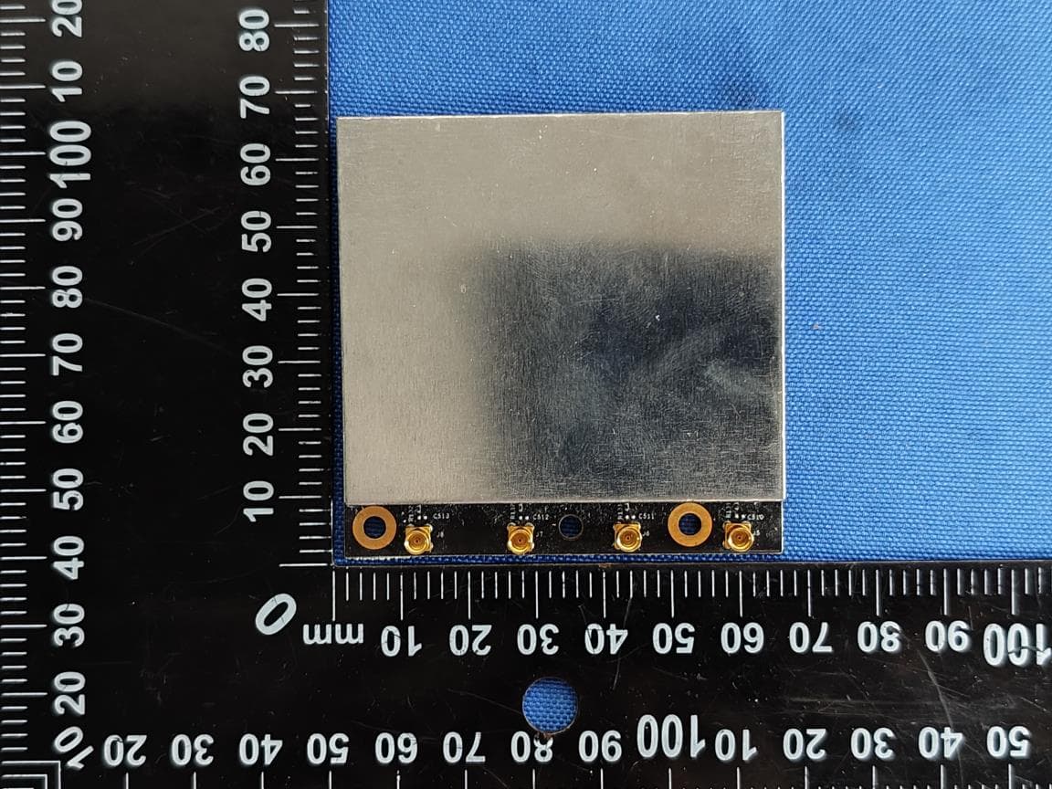
2ATPH-JS-WI-6
Mar 09, 2026RF PCBAs
Equipment Class
NII - Unlicensed National Information Infrastructure TX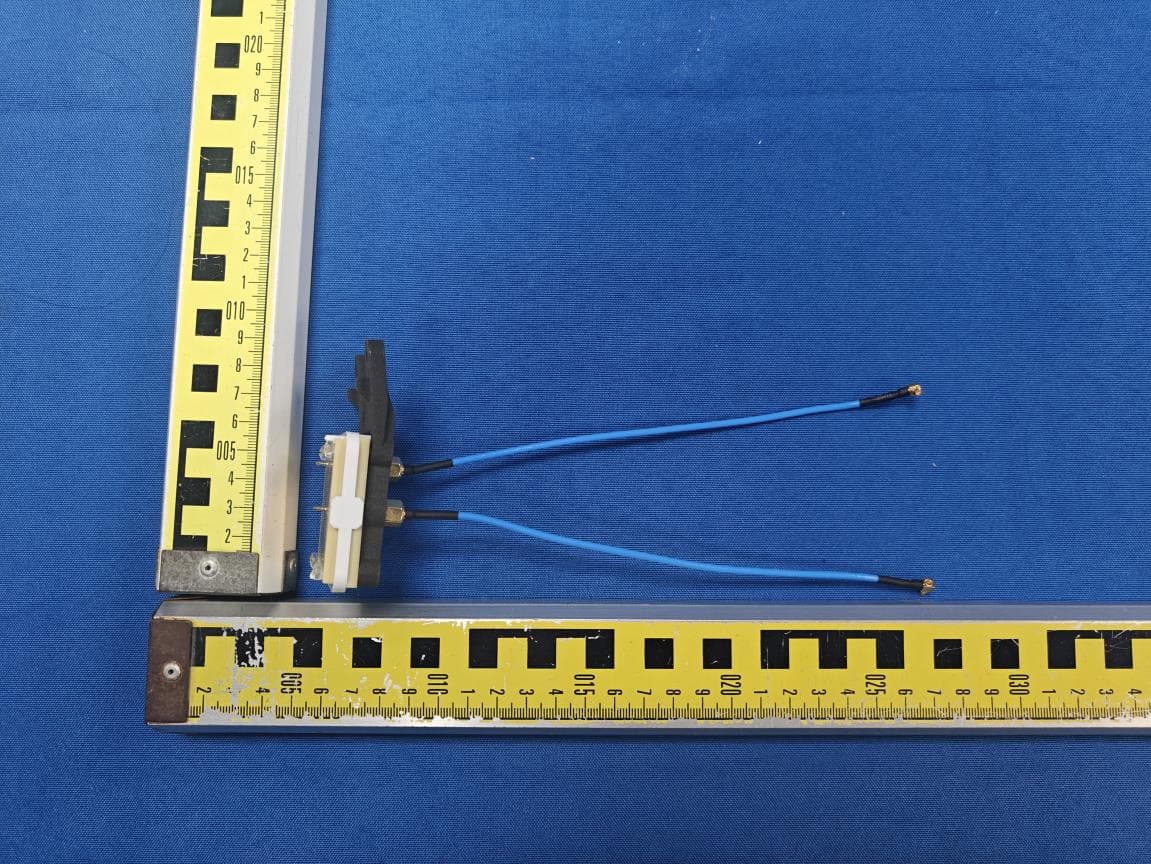
2ATPH-JS-WI-2-4
Mar 06, 2026RF PCBAs
Equipment Class
DTS - Digital Transmission System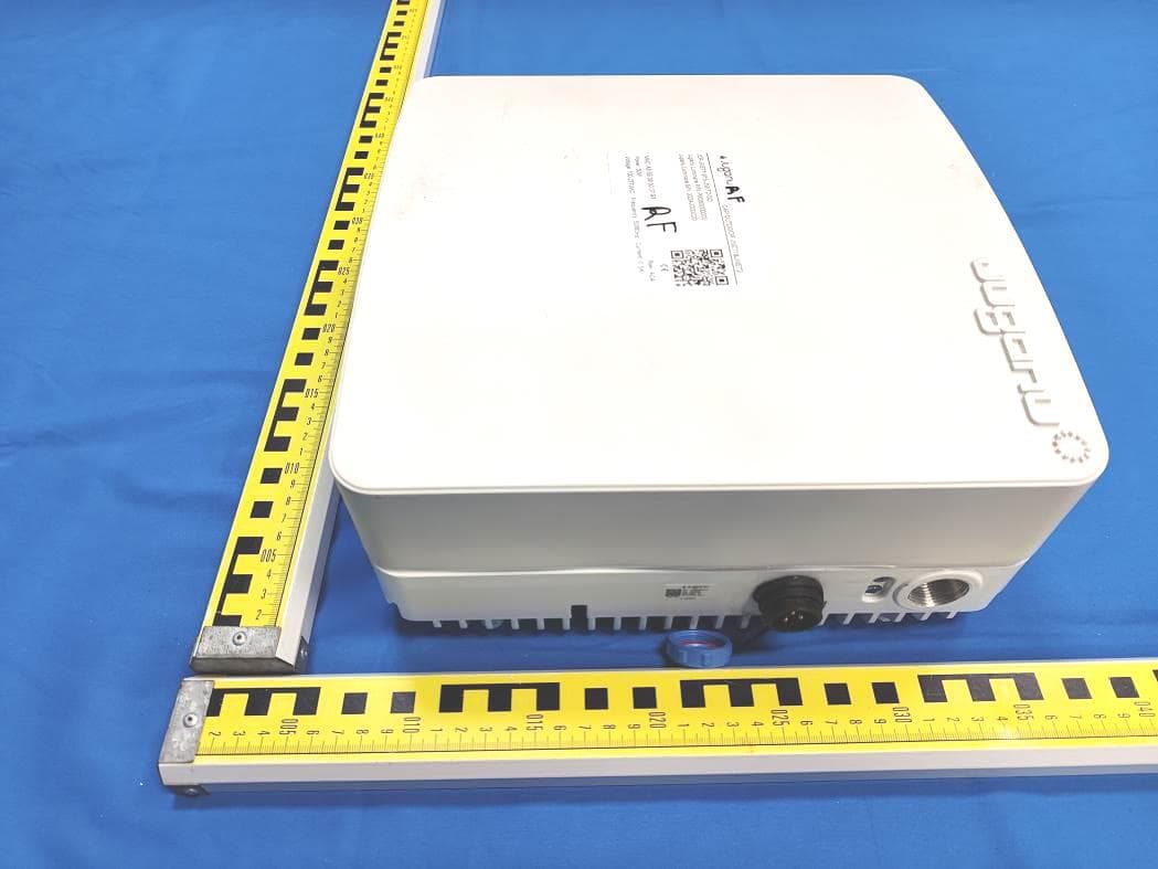
2ATPH-JNET2-OD
Jan 29, 2023CAP OUTDOOR
Equipment Class
NII - Unlicensed National Information Infrastructure TX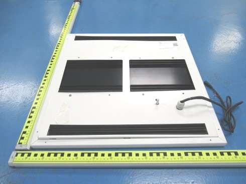
2ATPH-JPP
May 17, 2021JPROTECT
Equipment Class
CYY - Communications Receiver used w/Pt 15 Transmitter
2ATPH-JNET1-915MHZ
Jun 22, 2020RF module
Equipment Class
DTS - Digital Transmission System