AS5BBTRX-05PCS Wireless Base Station Transceiver
Nokia of America Corporation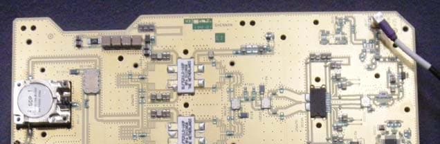
Click to zoom
Application Details
- Equipment Class
- PCB - PCS Licensed Transmitter
- Date of Grant
- Apr 29, 2012
- Application Purpose
- Original Equipment
- Date of Application
- Apr 29, 2012
- Equipment Note
- PCS Wireless Base Station Transceiver
- Frequency Range
- 1930.00000000 - 1995.00000000
- Company
- Nokia of America Corporation
- Country
- United States
Documents & Files
Document Text
Text extracted from the exhibit documents filed with the FCC. Open a document above to read the original.
Users Manual
APPLICANT: Alcatel-Lucent EXHIBIT 3 FCC ID: AS5BBTRX-05 Page 1 of 1 EXHIBIT 3 Section 2.1033 (c)(3) INSTALLATION AND OPERATING INSTRUCTIONS A copy of the installation and operating instructions to be furnished to the user. A draft copy of the instructions may be submitted if the actual document is not available. The actual document shall be furnished to the FCC when it becomes available. Response A copy of the “Alcatel-Lucent 9927 Distributed Base Station Outdoor Site Preparation Guidelines” manual is attached to this exhibit. Titlepage Alcatel-Lucent9927DistributedBaseStation OutdoorSitePreparationGuidelines 401-703-516 Issue1 | March2012 Alcatel-Lucent–Proprietary Usepursuanttoapplicableagreements Usepursuanttoapplicableagreements Legalnotice Legalnotice Alcatel,Lucent,Alcatel-LucentandtheAlcatel-LucentlogoaretrademarksofAlcatel-Lucent.Allothertrademarksarethepropertyoftheirrespective owners. Theinformationpresentedissubjecttochangewithoutnotice.Alcatel-Lucentassumesnoresponsibilityforinaccuraciescontainedherein. Copyright©2012Alcatel-Lucent.Allrightsreserved. Containsproprietary/tradesecretinformationwhichisthepropertyofAlcatel-Lucentandmustnotbemadeavailableto,orcopiedorusedbyanyoneoutside Alcatel-Lucentwithoutitswrittenauthorization. Nottobeusedordisclosedexceptinaccordancewithapplicableagreements. Notice EveryeffortwasmadetoensurethattheinformationinthisInformationProduct(IP)wascompleteandaccurateatthetimeofprinting.However, informationissubjecttochange. Orderinginformation Theorderingnumberforthisdocumentis401-703-516.ToorderthisorotherAlcatel-Lucentinformationproducts,see“Toobtaindocumentation,training, andtechnicalsupportorsubmitfeedback”ontheFlexent ® /AUTOPLEX ® WirelessNetworksSystemDocumentationCD-ROM,401-010-001orthe documentationwebsiteat (https://wireless.support.lucent.com/amps/rls_info/rls_doc/cd_docs/customer.support/customer.support_toc.pdf.wen). Technicalsupport Fortechnicalsupport,see“Toobtaindocumentation,training,andtechnicalsupportorsubmitfeedback”ontheFlexent ® /AUTOPLEX ® WirelessNetworks SystemDocumentationCD-ROM,401-010-001orthedocumentationwebsiteat((https://wireless.support.lucent.com/amps/rls_info/rls_doc/cd_docs/ customer.support/customer.support_toc.pdf.wen). Usepursuanttoapplicableagreements Alcatel-Lucent–Proprietary Usepursuanttoapplicableagreements AboutthisdocumentAboutthisdocument Purpose ThisInformationProduct(IP)describesthebasicsiterequirementsthatshouldbeusedto planaAlcatel-Lucent9927DistributedBaseStationoutdoorsite.Thisdocumentincludes specifictasksthatshouldbecompletedatthejobsitebeforeaninstallationcanbegin. Reasonforreissue ThisdocumentisAlcatel-Lucent9927DistributedBaseStationOutdoorSitePreparation Guidelines,documentnumber401-703-516,Issue1.Thisissueincorporatesinformation availableasofDecember2011. Thisisthesecondissueofthisdocument.Wheneverthisdocumentisreissued,the reasonsforreissuewillbeprovidedinthissection. Thereasonsforreissueareshowninthetablebelow. IssueReason 2 Intendedaudience ThisIPisintendedforcustomerspreparinga9927DistributedBaseStationoutdoorsite. Conventionsused ThefollowingconventionsareusedinthisIP: Measurements Allmeasurementsareshowninmetricform,andarefollowedbytheEnglishconversion inparentheses. ................................................................................................................................................................................................................................... 9927DistBTSOutdoor 401-703-516 Issue1 March2012 Alcatel-Lucent–Proprietary Usepursuanttoapplicableagreements xi Namingconventions InthisIP,theAlcatel-Lucent9927DistributedBaseStationOutdoorCabinetisreferred toas9927DistributedBaseStationOutdoorCabinet. Standardcross-sectionsandwirediametersofroundcopperconductors ThefollowingtableisfromCEI/IEC60947-1:2004,Table1,Standardcross-sectionsof roundcopperconductorsandapproximaterelationshipbetweenmm 2 andAWG/kcmil sizesforreference.Additionalwiresizesareincludedinthisinformationproductas appropriateforthetopic. ISOratedcross-sectionalarea(mm 2 ) AWG/kcmilsize 0.224 0.3422 0.520 0.7518 1- 1.516 2.514 412 610 108 166 254 352 -1 500(1/0) 7000(2/0) 95000(3/0) -0000(4/0) 120250kcmil 150300kcmil 185350kcmil -400kcmil 240500kcmil 300600kcmil Aboutthisdocument .................................................................................................................................................................................................................................... .................................................................................................................................................................................................................................... xii Alcatel-Lucent–Proprietary Usepursuanttoapplicableagreements 9927DistBTSOutdoor 401-703-516 Issue1 March2012 ISOratedcross-sectionalarea(mm 2 ) AWG/kcmilsize NOTE:Thedash,whenitappears,countsasasizewhenconsideringconnectingcapacity(see 7.1.7.2inthestandard). Relateddocumentation Basestationplannersandsitepreparationpersonnelmusthavetheappropriatereference material,andallapplicablelocal,regionalandnationalcodedocumentation. Alcatel-Lucentdocuments(required,orrequiredasapplicable) •GroundingandLightningProtectionGuidelinesforAlcatel-LucentNetworkWireless SystemCellSites,401-200-115 •InstallationInstructions,InterfaceKitforAttachmentof60ECv2BatteryCabinetto Outdoor9927BaseStationPrimaryCabinetwithIntegratedPower,109621573 •InstallationInstructions,InterfaceKitforNon-StandardAttachmentof60ECv2 BatteryCabinettoOutdoor9927BaseStationPrimaryCabinetwithIntegrated Power,109676239 •InstallationInstructions,InterfaceKitforInstallationofSecond60ECv2Battery CabinetwithFirst60ECv2BatteryCabinet,109683177 •EngineeringRulesforFlexent ® ModularCell4.0B,ER_0102_0004 •EngineeringRulesforFactoryandFieldInstallationKitsfor9927DistributedBase Station,ER_0105_0006 Otherdocuments(required) •StandardforInstallationofLightningProtectionSystems,NFPA780 •RecommendedPracticesonSurgeVol…
Text truncated - open the document above for the full version.
Attestation Statements
APPLICANT: Alcatel-Lucent EXHIBIT 2 FCC ID: AS5BBTRX-05 Page 1 of 2 EXHIBIT 2 Section 2.1033 (c)(1, 2, 4-7) INFORMATION OF MANUFACTURER, APPLICANT, IDENTIFIER, EMISSION TYPES, FREQUENCY RANGE, OPERATING POWER RANGE AND MAXIMUM POWER RATING Section 2.1033 (c)(1) NAME AND ADDRESS OF MANUFACTURER AND APPLICANT The full name and mailing address of the manufacturer of the device and the applicant for certification Response Manufacturer: Alcatel-Lucent USA Inc 600-700 Mountain Ave Murray Hill, New Jersey 07974 Applicant: Alcatel-Lucent USA Inc 600-700 Mountain Ave Murray Hill, New Jersey 07974 Section 2.1033 (c)(2) FCC IDENTIFIER Response FCC Identifier: AS5BBTRX-05. Section 2.1033(c)(4) TYPE OR TYPES OF EMISSION Response 1M25F9W and 5M00F9W. Section 2.1033(c)(5) FREQUENCY RANGE Response Transmit: 1930-1995MHz. Receive: 1850–1915 MHz. Section 2.1033(c)(6) OPERATING POWER RANGE AND ADJUSTMENT Range of operating power values or specific operating power levels, and description of any means provided for variation of operating power. Response The AS5BBTRX-05 PCS wireless base station, the subject of the application, is capable of producing RF carriers at the base station transmit antenna terminals at a maximum mean power level of 25W (+44dBm) per 1.25MHz bandwidth CDMA carrier and 20W (+43dBm) per 5MHz bandwidth LTE carrier, 45W (46.5dBm) per transmitting port for multi-carriers and 180 Watts (49dBm) per RRH at the base station transmitting antenna terminals. The PCS 4x45W RRH currently is available in indoor and outdoor versions. APPLICANT: Alcatel-Lucent EXHIBIT 2 FCC ID: AS5BBTRX-05 Page 2 of 2 There are three points within the transmit chain at which the gain can be adjusted. Within the Onyx FPGA (Field Programmable Gate Array) a function is provided to adjust the gain in each carrier branch and this is the only point in the CPR (common platform radio) TX chain where the gain of each carrier can be adjusted separately. The power can be configured from 1W to the maximum capacity of 45W (short term average) in each transmitting path. The gain of the composite multi-carrier path is adjusted by the RF voltage- variable attenuator to account for analogue gain variations in the Tx chain over temperature and frequency. This is referred to as CLGC (Closed Loop Gain Control). In addition, the Onyx FPGA can adjust the gain of the composite multi-carrier path by adjusting a digital scaler over a limited range but at high speed, this is referred to as FastCLGC. FastCLGC works in conjunction with CLGC. Section 2.1033(c)(7) MAXIMUM POWER RATING Maximum power rating as defined in the applicable part(s) of the rules. Response The maximum mean power rating of the AS5BBTRX-05 PCS base station is 25W (+44dBm) per 1.25MHz bandwidth CDMA carrier and 20W (+43dBm) per 5MHz bandwidth LTE carrier, 45W (46.5dBm) per transmitting port and 180 Watts (49dBm) per RRH for multi-carriers at the transmitting antenna terminal.
Attestation Statements
APPLICANT: Alcatel-Lucent EXHIBIT 6 FCC ID: AS5BBTRX-05 Page 1 of 1 EXHIBIT 6 Section 2.1033 (c)(10) CIRCUITRY AND DEVICES FOR SUPPRESSION OF SPURIOUS RADIATION A description of all circuitry and devices provided for suppression of spurious radiation. Response The Alcatel-Lucent Dual Technology PCS 4x45W RRH, subject of this application, were designed in adherence to the proper Electromagnetic Compatibility (EMC) guidelines extending from the circuit board level to the shelf and system levels to significantly suppress inter-modulation products, carrier induced harmonics and other spurious signals as well as the emissions radiated from them. The suppression of spurious radiation was achieved mainly by implementing the following two techniques: 1. Effective filtering in the RF path of the transceiver unit and band-pass transmit filters (external to the transceiver). 2. Proper grounding and RF shielding of the circuitry, circuit boards, cables, shelves and the frame.
Cover Letter(s)
- 1 - Alcatel-Lucent USA Rm. 28-114H 600-700 Mountain Ave. PO Box 636 Murray Hill, NJ 07974 April 24, 2012 Timco Engineering Inc. Telecommunication Certification Bodies 849 NW State Road 45 Newberry, Florida 32669 Subject: Application for Original Equipment Certification under FCC ID: AS5BBTRX-05 for RRH 4x45W Base Station, Operating in the Personal Communications Services, 1930-1995MHz, with LTE and CDMA Technologies Dear Examiner: In accordance with Parts 2 and 24 of the Commission’s Rules and Regulations, we are submitting herewith statements and supporting data to show compliance with the requirements of the Commission for the certification of the Alcatel-Lucent Dual Technology PCS (Personal Communications Services) Multiple Input Multiple Output (MIMO) Remote Radio Head (RRH) 4x45W, henceforth PCS RRH 4x45W, under FCC ID AS5BBTRX-05, for operation in the domestic PCS A, D, B, E, F, C and G bands (1930-1995 MHz), i.e., E- UTRAN band 25, with Code Division Multiple Access (CDMA) and Long Term Evolution (LTE) technologies. . The distributed wireless RRH base station system is comprised of two separate modules 1) the digital Base Band Unit (BBU) and 2) the RRH. These two modules are interconnected by Common Public Radio Interface (CPRI) though optic fiber or metallic coax cables when the separation is less than 3m for indoor deployment. The RRH contains all RF (radio frequency) functionality, including transceiver, power amplifier and transmitting and receiving filters. The BBU provides the digital baseband signals, plus the timing reference signal to the RRH. The BBU can be a unit specially designed for the distributed application or utilize the digital baseband shelf of a non-distributed base station system. The BBU and RRH units can be co-located or remotely located. The PCS RRH 4x45W supports multiple carriers and CDMA/LTE dual technology by sharing available TX power and bandwidth between two air interface technologies at each duplexed antenna port. It supports transmit diversity and/or MIMO operation for LTE. The hardware can support 4x4 MIMO for LTE. The software in the current release supports 2x2 MIMO only. The CDMA and/or 5MHz LTE carriers can be placed on all 4 TX/RX paths in a single sector. The PCS RRH 4x45W uses two 2x45W RRHs placed back to back inside a physical enclosure with two external CPRI interfaces: one from 3G BBU (CDMA) while the other one from 4G BBU (LTE). Internally, there is a daisy chaining of two CPRI ports enabling routing and managing the carriers (LTE and CDMA) across two logical halves of the RRH. Either CPRI port can be configured to be a Primary port. Each 2x45W RRH consists of one radio, one power amplifier and one transceiver filter with two Tx paths, dual PA pallet and dual Filter panel inside. Therefore, the PCS 4x45W RRH has four independent transmitting paths. The PCS RRH 4x45W has 4 antenna ports. It can provide up to 25 Watts (44dBm) per CDMA voice carrier and 20 Watts (43dBm) per 5MHz LTE carrier, 45 Watts (46.5dBm) per port for multi-carriers and 180 Watts (49dBm) per RRH at the base station transmitting antenna terminals. The PCS RRH 4x45W is powered by - 48VDC and currently is available in indoor and outdoor versions.
Cover Letter(s)
- 1 - Alcatel-Lucent USA 600-700 Mountain Ave., Rm 28-114H PO Box 636 Murray Hill, NJ 07974 April 27, 2012 Timco Engineering Inc. Telecommunication Certification Bodies 849 NW State Road 45 Newberry, Florida 32669 Subject: Request for Confidentiality for FCC ID: AS5BBTRX-05 Dear Examiner: Pursuant to Sections 0.457 & 0.459 of the Commission’s Rules, we request that the following exhibits, included in the certification application for the FCC ID: AS5BBTRX-05, be maintained as confidential information and not be made available for public inspection at any time. 1. Exhibit 5 Circuit Diagrams and Parts List 2. Exhibit 7 Description of Circuitry and Devices for Determining and Stabilizing Frequency and for Limiting Modulation and Power 3. Exhibit 10 Description of the Digital Modulation System These exhibits contain critical design information and are highly proprietary that cannot be made available for public inspection. This information is proprietary both to Alcatel-Lucent and to Alcatel-Lucent’s contracted design manufacturers. The proprietary information contained in these exhibits is considered to be trade secrets and the property of Alcatel-Lucent and its contracted design manufacturers, pursuant to the provisions of Section 0.457(d) of the Commission’s Rules and Section 552(b)(4) of the Freedom of Information Act.
External Photos
APPLICANT: Alcatel-Lucent EXHIBIT 9 FCC ID: AS5BBTRX-05 Page 1 of 7 EXHIBIT 9 Section 2.1033 (c)(12) PHOTOGRAPHS OF THE EQUIPMENT Photographs (8 x 10) of the equipment of sufficient clarity to reveal equipment construction and layout, including meters, if any, and labels for controls and meters and sufficient views of the internal construction to define component placement and chassis assembly. Insofar as these requirements are met by photographs or drawings contained in instruction manuals supplied with the certification request, additional photographs are necessary only to complete the required showing. Response The RF path of the PCS 4x45W RRH is comprised of two critical RF active components: the transceiver CRP1900 and power amplifier RHPA 1900. The following pages contain the required photographs of the AS5BBTRX-05 RRH, subject of this application, showing the external and internal views of the RRH and its two critical RF components. Seven photos in total were submitted, which include: 1) External Front and Side Views of the RRH, 2) External Front-Right Side-Bottom View of the RRH, 3) External Front-Left Side-Top View of the RRH, 4) Internal Views of the RRH: Top: RF Transmitting and Receiving Filter, Middle: Transceiver CRP1900 and Power Amplifier RHPA 1900, Bottom: PSU Circuit. 5) Front and Back Views of RHPA1900 6) Front and Rear Views of CRP1900 with Shielding Cover Removed 7) Front and Rear Views of RHPA1900 with Shielding Cover Removed APPLICANT: Alcatel-Lucent EXHIBIT 9 FCC ID: AS5BBTRX-05 Page 2 of 7 External Front and Side Views of the RRH APPLICANT: Alcatel-Lucent EXHIBIT 9 FCC ID: AS5BBTRX-05 Page 3 of 7 b External Front-Left Side-Top View of the RRH External Front-Right Side-Bottom View of the RRH APPLICANT: Alcatel-Lucent EXHIBIT 9 FCC ID: AS5BBTRX-05 Page 4 of 7 Internal Views of RRH APPLICANT: Alcatel-Lucent EXHIBIT 9 FCC ID: AS5BBTRX-05 Page 5 of 7 Front and Back Views of RHPA1900 APPLICANT: Alcatel-Lucent EXHIBIT 9 FCC ID: AS5BBTRX-05 Page 6 of 7 Front and Rear Views of CRP1900 with Shielding Cover Removed APPLICANT: Alcatel-Lucent EXHIBIT 9 FCC ID: AS5BBTRX-05 Page 7 of 7 Front and Rear Views of RHPA1900 with Shielding Cover Removed
ID Label/Location Info
APPLICANT: Alcatel-Lucent EXHIBIT 8 FCC ID: AS5BBRTX-05 Page 1 of 2 EXHIBIT 8 Section 2.1033 (c)(11) EQUIPMENT IDENTIFICATION LABEL A photograph or drawing of the equipment identification plate or label showing the information to be placed thereon. Response The equipment label to be affixed to the AS5BBRTX-05 will contain the following information. The engineering drawing and photos of the label are attached to this exhibit. Alcatel-Lucent RRH 1900-4x45 FCC ID: AS5BBTRX-05 REAR FRONT LEFT SIDE
ID Label/Location Info
APPLICANT: Alcatel-Lucent EXHIBIT 8 FCC ID: AS5BBRTX-05 Page 1 of 2 EXHIBIT 8 Section 2.1033 (c)(11) EQUIPMENT IDENTIFICATION LABEL A photograph or drawing of the equipment identification plate or label showing the information to be placed thereon. Response The equipment label to be affixed to the AS5BBRTX-05 will contain the following information. The engineering drawing and photos of the label are attached to this exhibit. Alcatel-Lucent RRH 1900-4x45 FCC ID: AS5BBTRX-05 REAR FRONT LEFT SIDE
Internal Photos
APPLICANT: Alcatel-Lucent EXHIBIT 9 FCC ID: AS5BBTRX-05 Page 1 of 7 EXHIBIT 9 Section 2.1033 (c)(12) PHOTOGRAPHS OF THE EQUIPMENT Photographs (8 x 10) of the equipment of sufficient clarity to reveal equipment construction and layout, including meters, if any, and labels for controls and meters and sufficient views of the internal construction to define component placement and chassis assembly. Insofar as these requirements are met by photographs or drawings contained in instruction manuals supplied with the certification request, additional photographs are necessary only to complete the required showing. Response The RF path of the PCS 4x45W RRH is comprised of two critical RF active components: the transceiver CRP1900 and power amplifier RHPA 1900. The following pages contain the required photographs of the AS5BBTRX-05 RRH, subject of this application, showing the external and internal views of the RRH and its two critical RF components. Seven photos in total were submitted, which include: 1) External Front and Side Views of the RRH, 2) External Front-Right Side-Bottom View of the RRH, 3) External Front-Left Side-Top View of the RRH, 4) Internal Views of the RRH: Top: RF Transmitting and Receiving Filter, Middle: Transceiver CRP1900 and Power Amplifier RHPA 1900, Bottom: PSU Circuit. 5) Front and Back Views of RHPA1900 6) Front and Rear Views of CRP1900 with Shielding Cover Removed 7) Front and Rear Views of RHPA1900 with Shielding Cover Removed APPLICANT: Alcatel-Lucent EXHIBIT 9 FCC ID: AS5BBTRX-05 Page 2 of 7 External Front and Side Views of the RRH APPLICANT: Alcatel-Lucent EXHIBIT 9 FCC ID: AS5BBTRX-05 Page 3 of 7 b External Front-Left Side-Top View of the RRH External Front-Right Side-Bottom View of the RRH APPLICANT: Alcatel-Lucent EXHIBIT 9 FCC ID: AS5BBTRX-05 Page 4 of 7 Internal Views of RRH APPLICANT: Alcatel-Lucent EXHIBIT 9 FCC ID: AS5BBTRX-05 Page 5 of 7 Front and Back Views of RHPA1900 APPLICANT: Alcatel-Lucent EXHIBIT 9 FCC ID: AS5BBTRX-05 Page 6 of 7 Front and Rear Views of CRP1900 with Shielding Cover Removed APPLICANT: Alcatel-Lucent EXHIBIT 9 FCC ID: AS5BBTRX-05 Page 7 of 7 Front and Rear Views of RHPA1900 with Shielding Cover Removed
Test Report
APPLICANT: Alcatel-Lucent EXHIBIT 11 AS5BBTRX-05 Page 1 of 34 EXHIBIT 11 TEST REPORT This t est re port prese nts t he measurement dat a re quired by t he C ommission for ce rtifying t he Al catel- Lucent CDMA-LTE 65MHz PCS RRH 4x45W, subject of this application, for operation in the domestic PCS A, D, B, E, F, C and G bands (1930-1995 MHz), with CDMA and LTE technologies. . As stated before, the distributed wireless RRH base station system is comprised of two separate modules 1) the BBU an d 2) the RRH. Th ese two modules are in terconnected by CPRI though optic fiber or metallic coax cab les. All RF fu nctionality is co ntained in the R RH, in cluding tran sceiver, po wer am plifier an d transmitting and receiving filters. The BBU provides the digital I and Q baseband signals, plus the timing reference signal to the RRH. The BBU and RRH units can be co-located or remotely located. The PCS 4x45W RR H supp orts m ultiple carriers and CD MA an d LTE du al techn ology by sharing available TX power and bandwidth between two ai r interface technologies at each antenna port. It also supports transmit diversity and/or MIMO operation (for LTE only). The hardware can support 4x4 MIMO for LTE. The software in the current release supports 2x2 MIMO only. The PCS 4x45W RRH has 4 antenna ports. The CDMA and/or 5MHz LTE carriers can be placed on all 4 TX/RX paths in a single sector. The PCS 4x45W RRH uses two 2x45W RRHs placed back to back inside a physical enclosure with two external CPRI interfaces: one from 3G BBU (CDMA) while the other one from 4 G BB U (LTE). In ternally, th ere i s a d aisy chaining o f t wo CPRI po rts e nabling r outing an d managing the carriers (LTE and CDMA) across two logi cal halves of t he RRH. Eithe r CPRI port ca n be configured to be a Pr imary port. Each 2x45W RRH consists of one radio CRP1900, one power amplifier RHPA1900 and one transceiver filter with two transmitting paths, dual PA p allet and dual Filter pan el inside. Therefore, the PCS 4x45W RRH has four independent transmitting paths. The PCS RRH can provide up to 25 Watts (44dBm) per CDMA carrier and 20 Watts (43dBm) per 5MHz LTE carrier, 45 Watts (46.5dBm) per port for multi-carriers and 180 Watts (49dBm) per RRH at t he base station tran smitting an tenna term inals. The PCS 4x45W RRH curren tly is po wered by -48 VDC and available in indoor and outdoor versions. All testing results submitted in this report were performed on the -48VDC CDMA-LTE PCS 4x45W RRH outdoor with the 9928 BBU during the period of February 1~ April 20, 2012. The above PCS 4x45W RRH passed FCC Part 15 Class A radiated emissions requirements. The performance of indoor version of the PCS 4x45W RRH will be evaluated and authorized through FCC Class I permissive change procedure. The measurement results have demonstrated that Alcatel-Lucent CDMA-LTE PCS 4x45W RRH is in full compliance with the Rules of the Commission. APPLICANT: Alcatel-Lucent EXHIBIT 11 AS5BBTRX-05 Page 2 of 34 SUBEXHIBIT 11.1 Section 2.1033 (c)(14) REQUIRED MEASUREMENT DATA The required measurement data is presented in the following exhibits as follows: SUBEXHIBIT 11.2 Section 2.1046 Measurements Required: RF Power Output SUBEXHIBIT 11.3 Section 2.1047 Modulation Characteristics SUBEXHIBIT 11.4 Section 2.1049, 24.238 Measurements Required: Occupied Bandwidth and Out-of-Band Emissions SUBEXHIBIT 11.5 Sections 2.1051, 24.238 Measurements Required: Spurious Emissions at Antenna Terminals SUBEXHIBIT 11.6 Sections 2.1053, 24.238 Measurements Required: Field Strength of Spurious Radiation SUBEXHIBIT 11.7 Sections 2.1055, 24.235 Measurements Required: Frequency Stability SUBEXHIBIT 11.8 Section 2.947 List of Test Equipment Used APPLICANT: Alcatel-Lucent EXHIBIT 11 AS5BBTRX-05 Page 3 of 34 SUBEXHIBIT 11.2 Section 2.1046 MEASUREMENT REQUIRED: RF POWER OUTPUT This test is a measurement of the total RF power level transmitted at the antenna-transmitting terminal (J4), as shown in the accompanying test set-up diagram. The radio was tuned to a channel which is transmitting in the 1930-1995MHz frequency band. The power level of the base station was calibrated to allow the base station to operate at the manufacturer’s maximum rated mean power level, i.e., +44dBm (25W) per carrier for CDMA, +43dBm (20W) per carrier for LTE, and +46.5 dBm (45W) per port at the antenna-transmitting terminal. For CDMA2000 voice application, all the carriers were configured with a combination of the Pilot, Sync, Paging and Traffic channels. The Pilot/Sync/Page channels were set up according to the recommended test model for base stations given in 3GPP2 C.S0010-C v 2.0 (Section 6) with 37 traffic channels for total power & conducted RF unwanted emissions measurements and 6 traffic channels for other tests, as shown in the following table. Table 11.2.1. Base Station Test Model Type Number of Channels Fraction of Power (linear) Fraction of Power (dB) Pilot 1 0.2000 -7.0 Sync 1 0.0471 -13.3 Paging 1 0.1882 -7.3 Traffic M 0.5647/M -2.48 - 10 log M For C DMA2000 hi gh rat e packet data a pplication, t he carri ers were co nfigured with t ime-division multiplexed Pilot Channel, the MAC (Medium Access Control) Channel with 14 active MAC indices, and the Forward Traffic or Control Channels in each ti me slot in accordance with 3GPP2 C.S.0032. All time- division multiplexed channels were transmitted at equal power. For LTE, the RF power output with QPSK, 16QAM and 64QAM modulation were measured respectively. Power measurements were made with a Hewlett-Packa rd Power Meter with 8481A Power Sensor (0.01 – 18 GHz) in the average mode. The test set-up for conducting the RF power output measurement is shown in the following figure. Before th e testing was started , the Base Statio n was g iven a su fficient “warm-up” period as required. The maximum rated mean power at the antenna transmitting terminal was measured for a single carrier and multiple carriers with CDMA voice and data and LTE technologies across PCS band 19…
Text truncated - open the document above for the full version.
Test Report
APPLICANT: Alcatel-Lucent TABLE OF CONTENTS FCC ID: AS5BBTRX-05 Page 1 of 1 TABLE OF CONTENTS Exhibit 1 Section 2.911 (d) Certifications and Qualifications Exhibit 2 Section2.1033 (c) (1, 2, 4-7) Manufacturer, Applicant, Identifier, Emission Types, Frequency Range, Operating Power Range and Maximum Power Rating Exhibit 3 Section 2.1033 (c)(3) Installation and Operating Instructions Exhibit 4 Section 2.1033 (c)(8, 9) DC Voltages and Currents; Tune-up Procedure Exhibit 5 Section 2.1033 (c)(10) Circuit Schematic Diagrams and Parts list -> Confidential Exhibit 6 Section 2.1033 (c)(10) Circuitry and Devices for Suppression of Spurious Radiation Exhibit 7 Section 2.1033 (c)(10) Circuitry for Determining and Stabilizing Frequency and for Limiting Modulation and Power -> Confidential Exhibit 8 Section 2.1033 (c) (11) Equipment Identification Label Exhibit 9 Section 2.1033 (c) (12) Photograph of the Equipment Exhibit 10 Section 2.1033 (c) (13) Description of the Digital Modulation System -> Confidential Exhibit 11 Test Report Subexhibit 11.1 Section 2.1033 (c)(14) Required Measurement Data Subexhibit 11.2 Section 2.1046 Measurements Required: RF Power Output Subexhibit 11.3 Section 2.1047 Measurements Required: Modulation Characteristics Subexhibit 11.4 Section 2.1049, 24.238 Measurements Required: Occupied Bandwidth and Out-of- Band Emissions Subexhibit 11.5 Section 2.1051, 24.238 Measurements Required: Spurious Emissions at Antenna Terminal Subexhibit 11.6 Section 2.1053, 24.238 Measurements Required: Field Strength of Spurious Radiation Subexhibit 11.7 Section 2.1055, 24.235 Measurements Required: Frequency Stability Subexhibit 11.8 Section 2.947 (d) List of Test Equipment Used Appendix Acronyms
Test Report
APPLICANT: Alcatel-Lucent APPENDIX FCC ID : AS5BBTRX-05 Page 1 of 1 ACRONYMS The acronyms used in this application are listed in the following: BBU Base Band Unit CDMA Code Division Multiple Access CLGC Closed Loop Gain Control CLPD Complex Programmable Logic Device CMU CDMA Modem Units CPR Common Platform Radio CPRI Common Public Radio Interface CTU Common Timing Unit D/A Digital to Analog EAC External Antenna Connector EDPD Enhanced Digital Pre-Distortion EUT Equipment Under Test EVDO Evolution Data Only or Evolution Data Optimized EVM Error Vector Magnitude FPGA Field Programmable Gate Array GPS Global Positioning System IF Intermediate Frequency LTE Long Term Evolution MAC Medium Access Control MMBTS Multi-Mode Base Transceiver Station MIMO Multiple Input Multiple Output OCM Optical CPRI Module OFDM Orthogonal Frequency Division Multiplex OFDMA Orthogonal Frequency Division Multiple Access OM Oscillator Modules OMQM Oscillator Module, Quartz, Mezzanine PA Power Amplifier PAR Peak to Average Ratio PCS Personal Communications Services PDSCH Physical Downlink Shared Channel PLL Phase Lock Loop PSU Power Supply Unit PSK Phase Shift Keying QAM Quadrature Amplitude Modulation QPSK Quadrature Phase shift Keying RHPA Radio Head Power Amplifier RRH Remote Radio Head RF Radio Frequency URC Universal Radio Controller
Contact Information
Applicant
Raymond J. Johnson(Technical Manager)
Technical Specifications
| # | Rule Parts | Frequency Range | Power Output | Emission | Tolerance |
|---|---|---|---|---|---|
| 2 | 24E | 1.93 GHz - 2.00 GHz | 20 W | 5M00F9W | 0.05 ppm |
Other Applications from Nokia of America Corporation

AS5BBTRX-23
Mar 15, 2015B13 RRH 4X30
Equipment Class
TNB - Licensed Non-Broadcast Station Transmitter
AS5BBTRX-21
Feb 01, 2015PCS LTE 9764 Metro Cell Outdoor Transceiver System
Equipment Class
PCB - PCS Licensed Transmitter
AS5BBTRX-22
Jan 26, 2015B25 RRH 4X30
Equipment Class
PCB - PCS Licensed Transmitter
AS5BBTRX-17
Jan 08, 2014AWS LTE 9764 Metro Cell Outdoor Transceiver System
Equipment Class
TNB - Licensed Non-Broadcast Station Transmitter
AS5BBTRX-14
Dec 18, 20139763 MCI B25 PCS LTE 2x250mW
Equipment Class
PCB - PCS Licensed Transmitter