AS5BBTRX-08700U WIRELESS BASE STATION
Nokia of America Corporation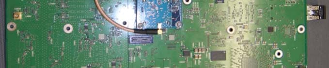
Click to zoom
Application Details
- Equipment Class
- TNB - Licensed Non-Broadcast Station Transmitter
- Date of Grant
- Mar 10, 2013
- Application Purpose
- Original Equipment
- Date of Application
- Mar 10, 2013
- Equipment Note
- 700U WIRELESS BASE STATION
- Frequency Range
- 746.00000000 - 756.00000000
- Company
- Nokia of America Corporation
- Country
- United States
Documents & Files
Document Text
Text extracted from the exhibit documents filed with the FCC. Open a document above to read the original.
Users Manual
APPLICANT: Alcatel-Lucent EXHIBIT 3 FCC ID: AS5BBTRX-08 Page 1 of 1 EXHIBIT 3 Section 2.1033 (c)(3) INSTALLATION AND OPERATING INSTRUCTIONS A copy of the installation and operating instructions to be furnished to the user. A draft copy of the instructions may be submitted if the actual document is not available. The actual document shall be furnished to the FCC when it becomes available. Response A copy of Alcatel-Lucent 9764 LightRadio™ Metro Cell Outdoor B13 LTE 2x5W Hardware Installation manual is attached to this exhibit. Alcatel-Lucent 9764 lightRadioTM Metro Cell Outdoor V1.0 B13 LTE 2x5W Hardware Installation 3MN-01651-0002-RJZZA Issue 0.05 | January 2013 Alcatel-Lucent – Proprietary Use pursuant to applicable agreements Legal notice Alcatel, Lucent, Alcatel-Lucent and the Alcatel-Lucent logo are trademarks of Alcatel-Lucent. All other trademarks are the property of their respective owners. The information presented is subject to change without notice. Alcatel-Lucent assumes no responsibility for inaccuracies contained herein. Copyright © 2013 Alcatel-Lucent. All rights reserved. Contains proprietary/trade secret information which is the property of Alcatel-Lucent and must not be made available to, or copied or used by anyone outside Alcatel-Lucent without its written authorization. Not to be used or disclosed except in accordance with applicable agreements. Alcatel-Lucent – Proprietary Use pursuant to applicable agreements About this document Purpose The purpose of this document is to provide hardware installation instructions for an Alcatel-Lucent Metro Cell Outdoor LTE 2x5W BC13 700 MHz. Procedures are provided for mounting, grounding, powering, and cabling the Metro Cell. Reason for reissue The reissue reasons are: Issue number Issue Date Reason for reissue 0.05 January 2013 Further updates 0.04 September 2012 Post GCD review 0.03 May 2012 Post mock install 0.02 May 2012 Post review 0.01 April 2012 Review New in this release This is a new document. Intended audience The audience for this document is Installation personnel. Supported systems This document applies to the Alcatel-Lucent 9764 lightRadio TM Metro Cell Outdoor 2x5W B13 LTE product. 9764 MCO B13 LTE 2x5W Alcatel-Lucent – Proprietary xi 3MN-01651-0002-RJZZA Use pursuant to applicable agreements Issue 0.05 January 2013 How to use this document Start with the first chapter and work through the manual to the end. Once you have done this, you will have carried out the hardware installation completely and in the proper sequence. Prior to installing the cabinet, the installer should be familiar with the safety precautions, warnings, and product conformance statements. Required tools and materials recommended for installation, and a process checklist, are listed in topic “Pre-installation information”. Safety information For your safety, this document contains safety statements. Safety statements are given at points where risks of damage to personnel, equipment, and operation may exist. Failure to follow the directions in a safety statement may result in serious consequences. Prerequisites None Conventions used Vocabulary conventions In this document, all parts are described as they are shipped. Metric parts are specified in metric units. Non-metric parts are specified in non-metric units. Lengths and other measurements are given in metric units, with non-metric units given as equivalents for use in non-metric markets. For manufactured parts, the following system of conventions is used: Metric sizes of nuts, bolts, flat washers, and lock washers are identified by an uppercase letter M followed immediately by a size in millimeters (example: M10) American fractional sizes of nuts, bolts, anchor bolts, and washers are identified by a number followed immediately by a double apostrophe (example: 3/8"). In the case of lengths measured in feet, “2 feet” is used rather than “2'” so that the single apostrophe is not overlooked. The illustrations in this document do not contain all details and exceptions, but are intended to highlight main points. Dimensions are usually shown in millimeters, with inches in parentheses. For example, 680.0 (26.77) equals 680 millimeters or 26.77 inches. Wire gauges are specified in metric units. Equivalent sizes in the American Wire Gauge (AWG) system are given in the following table: Standard cross-sections and wire diameter of round copper conductors xii Alcatel-Lucent – Proprietary 9764 MCO B13 LTE 2x5W Use pursuant to applicable agreements 3MN-01651-0002-RJZZA Issue 0.05 January 2013 About this document The following table is from CEI/IEC 60947-1:2004, Table 1, Standard cross-sections of round copper conductors and approximate relationship between mm 2 and AWG/kcmil sizes for reference. Additional wire sizes are included in this document as appropriate for the topic. ISO rated cross-sectional area (mm 2 ) AWG/kcmil size 0.2 24 0.34 22 0.5 20 0.75 18 1 - 1.5 16 2.5 14 4 12 6 10 10 8 16 6 25 4 35 2 - 1 50 0 (1/0) 70 00 (2/0) 95 000 (3/0) - 0000 (4/0) 120 250 kcmil 150 300 kcmil 185 350 kcmil - 400 kcmil 240 500 kcmil 300 600 kcmil NOTE: The dash, when it appears, counts as a size when considering connecting capacity (see 7.1.7.2 in the standard). 9764 MCO B13 LTE 2x5W Alcatel-Lucent – Proprietary xiii 3MN-01651-0002-RJZZA Use pursuant to applicable agreements Issue 0.05 January 2013 About this document Typographical conventions The following typographical conventions are used in this document: Appearance Description italicized text File and directory names Emphasized information IP reference, reference number Related document that is referenced in the document Related information For information on subjects related to the content of this document, refer to the documents listed in the following table: Refer to this document At this location For more information on Alcatel-Lucent Metro Cell Outdoor LTE 2x5W BC13 700 MHz - Site Preparation, 401-382-030 http://www.cic.lucent.com/ Site preparation …
Text truncated - open the document above for the full version.
Cover Letter(s)
APPLICANT: Alcatel-Lucent APPENDIX FCC ID : AS5BBTRX-08 Page 1 of 1 ACRONYMS The acronyms used in this application are listed in the following: CLGC Closed Loop Gain Control CPLD Complex Programmable Logic Device DA Board Digital/RF Analog Board DAC Digital to Analog Converter DSA Digital Step Attenuator EAC External Antenna Connector EIRP Equivalent or Effective Isotropically Radiated Power EUT Equipment Under Test E-UTRA Evolved Universal Terrestrial Radio Access EVM Error Vector Magnitude FPGA Field Programmable Gate Array GPS Global Positioning System IF Intermediate Frequency LTE Long Term Evolution MIMO Multiple Input Multiple Output OCXO Oven Controlled Crystal Oscillators OFDM Orthogonal Frequency Division Multiplex OFDMA Orthogonal Frequency Division Multiple Access PA Power Amplifier PAR Peak to Average Ratio PLL Phase Lock Loop PSU Power Supply Unit PSK Phase Shift Keying QAM Quadrature Amplitude Modulation QPSK Quadrature Phase shift Keying RF Radio Frequency
Cover Letter(s)
APPLICANT: Alcatel-Lucent TABLE OF CONTENTS FCC ID: AS5BBTRX-08 Page 1 of 1 TABLE OF CONTENTS Exhibit 1 Section 2.911 (d) Certifications and Qualifications Exhibit 2 Section2.1033 (c) (1, 2, 4-7) Manufacturer, Applicant, Identifier, Emission Types, Frequency Range, Operating Power Range and Adjustment and Maximum Power Rating Exhibit 3 Section 2.1033 (c)(3) Installation and Operating Instructions Exhibit 4 Section 2.1033 (c)(8, 9, 10) DC Voltages and Currents; Tune-up Procedure; Circuitry and Devices for Suppression of Spurious Radiation Exhibit 5 Section 2.1033 (c)(10) Circuit Schematic Diagrams and Parts list -> Confidential Exhibit 6 Section 2.1033 (c)(10, 13) Description of Circuitry and Devices for Determining and Stabilizing Frequency and for Limiting Modulation and Power and Description of the Digital Modulation System -> Confidential Exhibit 7 Section 2.1033 (c)(11) Equipment Identification Label Exhibit 8 Section 2.1033 (c) (12) Photograph of the Equipment Exhibit 9 Test Report Subexhibit 9.1 Section 2.1033 (c)(14) Required Measurement Data Subexhibit 9.2 Section 2.1046 Measurements Required: RF Power Output Subexhibit 9.3 Section 2.1047 Measurements Required: Modulation Characteristics Subexhibit 9.4 Section 2.1049, 27.53(c) Measurements Required: Occupied Bandwidth and Out-of- Band Emissions Subexhibit 9.5 Section 2.1051, 27.53(c) Measurements Required: Spurious Emissions at Antenna Terminal Subexhibit 9.6 Section 2.1053, 27.53(c) & (f) Measurements Required: Field Strength of Spurious Radiation Subexhibit 9.7 Section 2.1055, 27.54 Measurements Required: Frequency Stability Subexhibit 9.8 Section 2.947 (d) List of Test Equipment Used Appendix Acronyms
External Photos
APPLICANT: Alcatel-Lucent EXHIBIT 8 FCC ID: AS5BBTRX-08 Page 1 of 4 EXHIBIT 8 Section 2.1033 (c)(12) PHOTOGRAPHS OF THE EQUIPMENT Photographs (8 x 10) of the equipment of sufficient clarity to reveal equipment construction and layout, including meters, if any, and labels for controls and meters and sufficient views of the internal construction to define component placement and chassis assembly. Insofar as these requirements are met by photographs or drawings contained in instruction manuals supplied with the certification request, additional photographs are necessary only to complete the required showing. Response The following pages contain the required external photographs of the AS5BBTRX-08 MCO, subject of this application. Six photos in total were submitted, which include: 1) External Front and Back Views of the MCO, 2) External Top and Bottom Views of the MCO, 3) External Two Sides Views of the MCO. APPLICANT: Alcatel-Lucent EXHIBIT 8 FCC ID: AS5BBTRX-08 Page 2 of 4 External Front and Back Views of the MCO APPLICANT: Alcatel-Lucent EXHIBIT 8 FCC ID: AS5BBTRX-08 Page 3 of 4 External Top and Bottom Views of the MCO APPLICANT: Alcatel-Lucent EXHIBIT 8 FCC ID: AS5BBTRX-08 Page 4 of 4 External Two Sides Views of the MCO
ID Label/Location Info
APPLICANT: Alcatel-Lucent EXHIBIT 7 FCC ID: AS5BBRTX-08 Page 1 of 2 EXHIBIT 7 Section 2.1033 (c)(11) EQUIPMENT IDENTIFICATION LABEL A photograph or drawing of the equipment identification plate or label showing the information to be placed thereon. Response The engineering drawing of the equipment identification label to be affixed is attached to this exhibit. COMCODE: 849158274 ISSUE#: 3 WORK#: 5 MAR-TEK INDUSTRIES: ISO 9001:2008 REGISTERED COMCODE: 849158274 ISSUE#: 3 WORK#: 5 MAR-TEK INDUSTRIES: ISO 9001:2008 REGISTERED 0.00 52.88 0.00 143.73 11 & 9pt Frutiger Roman, 6.5pt Helvetica Bold & 7 & 6pt Helvetica Med Condensed ORIGINAL ARTWORK USE FOR REPRODUCTION COMPOSITE SPEC DRAWING FOR REFERENCE ONLY (DO NOT USE FOR REPRODUCTION) Title: 849158274 BOILERPLATE LABEL Designer: JB Drawn: SRJ Checked: Date: 02-19-2013 Date: 02-20-2013 Date: Approved: Date: Client: Alcatel-Lucent - Jim Butler Material Specifications: Font Info: Comcode No.: 849158274 Artmaster Issue#: 3w5 10 mil velvet/matte polycarbonate 8B35V (VTM-2) or equivalent with 3M 467 permanent adhesive Subsurface print Black and Cool Gray 1 OS20000 Drawing Issue#: Mar-Tek Industries • 3545-G South Platte River Drive • Englewood, CO 80110 • tele: 973-293-0165 • fax: 973-293-0164 • email: [email protected] AM ISSUE DESCRIPTIONDATEDRAWN 1w1Initial Release.05-07-2012S. JENSEN 1w2Remove area for MAC address label05-16-2012S. JENSEN 2w3Update electrical/voltage info06-08-2012S. JENSEN 3w4Change enclosure to Type 4, add CSA, change China RoHS to ʻeʼ08-28-2012S. JENSEN 3w5Add China 50 RoHS, area for CSA & add FCC number02-20-2013S. JENSEN Certifications: ALL INFORMATION CONTAINED IN THIS DOCUMENT IS THE PROPERTY OF ALCATEL-LUCENT All units are in millimeters • Tolerance is: 2 places .25mm • Symbology agrees with: ISO 1101 and ISO 1302 Labels are RoHS compliant and conform to Alcatel-Lucent banned substance and environmental hazardous substance requirements in QPS 20.248 & IAA 00266 0035 ASZZA. Artmaster Must Be Obtained By: Label shall meet UL and CSA requirements where applicable. Vendor must be UL and/or CSA approved. Documentation verifying the vendorʼs certifications for the material shall be provided by the vendor with each package/container. 112.00 X 40.00 R 1.50 KISS CUT 12.50 X 11.00 R 1.50 KISS CUT FCC ID NUMBER IS 7PT HELVETICA MED CONDENSED FONT Power AC Input: 100-240V~, 2A, 50/60Hz Type 4 Enclosure For Operating Temperature Ratings Reference The Site Preparation Document Manufactured by Alcatel-Lucent849158274 9764 MetroCell Outdoor B13 2x5W 4G/LTE apply MRI label here area for CSA label This device complies with Part 15 of the FCC Rules. Operation is subject to the condition that this device does not cause harmful interference. FCC ID: AS5BBTRX-08 ® Power AC Input: 100-240V~, 2A, 50/60Hz Type 4 Enclosure For Operating Temperature Ratings Reference The Site Preparation Document Manufactured by Alcatel-Lucent849158274 9764 MetroCell Outdoor B13 2x5W 4G/LTE apply MRI label here area for CSA label This device complies with Part 15 of the FCC Rules. Operation is subject to the condition that this device does not cause harmful interference. FCC ID: AS5BBTRX-08 ®
Internal Photos
APPLICANT: Alcatel-Lucent EXHIBIT 8 FCC ID: AS5BBTRX-08 Page 1 of 4 EXHIBIT 8 Section 2.1033 (c)(12) PHOTOGRAPHS OF THE EQUIPMENT Photographs (8 x 10) of the equipment of sufficient clarity to reveal equipment construction and layout, including meters, if any, and labels for controls and meters and sufficient views of the internal construction to define component placement and chassis assembly. Insofar as these requirements are met by photographs or drawings contained in instruction manuals supplied with the certification request, additional photographs are necessary only to complete the required showing. Response The RF path of the MCO 2x5W wireless base station is comprised of two critical RF active components: DA board and PA board. The following pages contain the required photographs of the AS5BBTRX-08 MCO, subject of this application, showing the internal views of the MCO critical RF components. Six photos in total are submitted, which include: 1) Front and Rear Views of DA Board 2) Front and Rear Views of PA Board 3) Front and Rear Views of PA Board with Shielding Cover Removed APPLICANT: Alcatel-Lucent EXHIBIT 8 FCC ID: AS5BBTRX-08 Page 2 of 4 Front and Rear Views of D/A Board APPLICANT: Alcatel-Lucent EXHIBIT 8 FCC ID: AS5BBTRX-08 Page 3 of 4 Front and Rear Views of PA Board APPLICANT: Alcatel-Lucent EXHIBIT 8 FCC ID: AS5BBTRX-08 Page 4 of 4 Front and Rear Views of PA Board with Shielding Cover Removed
Operational Description
APPLICANT: Alcatel-Lucent EXHIBIT 2 FCC ID: AS5BBTRX-08 Page 1 of 2 EXHIBIT 2 Section 2.1033 (c)(1, 2, 4-7) INFORMATION OF MANUFACTURER, APPLICANT, IDENTIFIER, EMISSION TYPES, FREQUENCY RANGE, OPERATING POWER RANGE AND MAXIMUM POWER RATING Section 2.1033 (c)(1) NAME AND ADDRESS OF MANUFACTURER AND APPLICANT The full name and mailing address of the manufacturer of the device and the applicant for certification Response Manufacturer: Alcatel-Lucent USA Inc 600-700 Mountain Ave Murray Hill, New Jersey 07974 Applicant: Alcatel-Lucent USA Inc 600-700 Mountain Ave Murray Hill, New Jersey 07974 Section 2.1033 (c)(2) FCC IDENTIFIER Response FCC Identifier: AS5BBTRX-08. Section 2.1033(c)(4) TYPE OR TYPES OF EMISSION Response 10M00F9W. Section 2.1033(c)(5) FREQUENCY RANGE Response Transmit: 746-756 MHz. Receive: 777–787 MHz. Section 2.1033(c)(6) OPERATING POWER RANGE AND ADJUSTMENT Range of operating power values or specific operating power levels, and description of any means provided for variation of operating power. Response The AS5BBTRX-08 700 Upper C band MCO 2x5W wireless base station, the subject of the application, is capable of producing one 10MHz bandwidth LTE RF carrier per transmitting port and two carriers per base station at a maximum mean power level of 5W (+37dBm) per carrier and per port and 10 Watts (40dBm) in total per base station at the transmit antenna terminals. The 700U MCO 2x5W currently is available in outdoor version only. APPLICANT: Alcatel-Lucent EXHIBIT 2 FCC ID: AS5BBTRX-08 Page 2 of 2 The Tx output power is controlled by the RF Digital Step Attenuator (DSA) via software over 12 dB range from +25dBm to +37dBm, respectively. The gain of the Tx path is adjusted by the DSA to account for gain variations in the Tx chain over operating temperature and frequency ranges. In addition to that, the FPGA provides fine output power control with a high resolution. The Tx chain parameters are carefully characterized during manufacturing process and provide high accuracy of setting the Tx output power and maintaining it over operating frequency and temperature ranges. Section 2.1033(c)(7) MAXIMUM POWER RATING Maximum power rating as defined in the applicable part(s) of the rules. Response The maximum mean power rating of the AS5BBTRX-08 700 Upper C Band MCO wireless base station at the base station transmitting antenna terminals is 5W (+37dBm) per 10MHz bandwidth LTE carrier and per transmitting port and 10 Watts (40dBm) for two ports per MCO. The 700U MCO supports a single 10MHz LTE carrier per transmitting path only.
Parts List/Tune Up Info
APPLICANT: Alcatel-Lucent EXHIBIT 4 FCC ID: AS5BBTRX-08 Page 1 of 1 EXHIBIT 4 Section 2.1033 (c)(8) DC VOLTAGES AND CURRENTS The dc voltage applied to and dc currents into the several elements of the final radio frequency amplifying device for normal operation over the power range. Response The single phase, three wire AC voltage source in the range of 160 to 264 VAC and 47 to 63Hz is applied to the 9764 700U MCO 2x5W, the transceiver system. The 28 VDC and 5.3 VDC nominal output voltages are applied to the final radio frequency amplifying device, Power Amplifier board, and the 5.3 VDC nominal output voltage is applied to the Digital and RF Analog board. The maximum rated power at the antenna terminals is 37 dBm, which corresponds to the maximum rated power at the PA output terminal of 38.5 dBm. At this power level, the PA nominal voltage and current rating is +28 VDC at 1.15 ADC. The worst case maximum current, in event of a 3dB overdrive condition, could have an excursion up to 1.6 ADC. Section 2.1033 (c)(9) TUNE-UP PROCEDURE Turn-up procedure over the power range, or at specific operating power levels. Response The Alcatel-Lucent 700U MCO 2x5W, subject of this application, cannot be “tuned-up” by the user. There are no user tune-up features. All tuning is performed by the manufacturer during, and as part of, the manufacturing process. Section 2.1033 (c)(10) CIRCUITRY AND DEVICES FOR SUPPRESSION OF SPURIOUS RADIATION A description of all circuitry and devices provided for suppression of spurious radiation. Response The Alcatel-Lucent LTE 700U MCO 2x5W, subject of this application, was designed in adherence to the proper Electromagnetic Compatibility (EMC) guidelines extending from the circuit board level to the shelf and system levels to significantly suppress inter-modulation products, carrier induced harmonics and other spurious signals as well as the emissions radiated from them. The suppression of spurious radiation was achieved mainly by implementing the following two techniques: 1. Effective filtering in the RF path of the transceiver unit and band-pass transmit filters (external to the transceiver). 2. Proper grounding and RF shielding of the circuitry, circuit boards, cables, shelves and the frame.
Test Report
APPLICANT: Alcatel-Lucent EXHIBIT 9 AS5BBTRX-08 Page 1 of 22 EXHIBIT 9 TEST REPORT This test report presents the measurement data required by the Commission for certifying the Alcatel- Lucent LTE 9764 700U MIMO Metro Cell 2x5W, subject of this application, for operation in the domestic 700 Upper Band C Band (Tx: 746-756 MHz and Rx: 777-787 MHz), i.e., E-UTRAN band 13, with Long Term Evolution (LTE) technology. . As stated before, the Metro 2x5W consists of a Digital/RF Analog board (DA), Power Amplifier Board (PA), Power Module and RF Filter. The Metro 2x5W has two antenna ports and supports MIMO with 2 transmit and 2 receive streams. The maximum output power is 37dBm (5W) per 10 MHz LTE carrier and per port and 10W per unit. All testing results submitted in this report were performed on the ALU LTE 9764 700U 2x5W Metro-Cell outdoor (AC) during the period of October 1, 2012~ January 15, 2013. The above 700U 2x5W MCO passed FCC Part 15 Class A radiated emissions requirements. The performance of indoor version of the 700U 2x5W MCO will be evaluated and authorized through FCC Class I permissive change procedure once it is available. The measurement results have demonstrated that Alcatel-Lucent 9764 LTE 700U 2x5W MCO is in full compliance with the Rules of the Commission. APPLICANT: Alcatel-Lucent EXHIBIT 9 AS5BBTRX-08 Page 2 of 22 SUBEXHIBIT 9.1 Section 2.1033 (c)(14) REQUIRED MEASUREMENT DATA The required measurement data is presented in the following exhibits as follows: SUBEXHIBIT 9.2 Section 2.1046 Measurements Required: RF Power Output SUBEXHIBIT 9.3 Section 2.1047 Modulation Characteristics SUBEXHIBIT 9.4 Section 2.1049, 27.53(c) Measurements Required: Occupied Bandwidth and Out-of-Band Emissions SUBEXHIBIT 9.5 Sections 2.1051, 27.53(c) Measurements Required: Spurious Emissions at Antenna Terminals SUBEXHIBIT 9.6 Sections 2.1053, 27.53(c) & (f) Measurements Required: Field Strength of Spurious Radiation SUBEXHIBIT 9.7 Sections 2.1055, 27.54 Measurements Required: Frequency Stability SUBEXHIBIT 9.8 Section 2.947 List of Test Equipment Used APPLICANT: Alcatel-Lucent EXHIBIT 9 AS5BBTRX-08 Page 3 of 22 SUBEXHIBIT 9.2 Section 2.1046 MEASUREMENT REQUIRED: RF POWER OUTPUT This test is a measurement of the total RF power level transmitted at the antenna-transmitting terminal (J4), as shown in the accompanying test set-up diagram. The radio was tuned to a channel which is transmitting in the 746-756MHz frequency band. The power level of the base station was calibrated to allow the base station to operate at the manufacturer’s maximum rated mean power level, i.e., +37dBm (5W) per 10MHz LTE carrier at the antenna-transmitting terminal. For LTE, the RF power output with QPSK, 16QAM and 64QAM modulation were measured respectively. Power measurements were made with a Hewlett-Packard Power Meter with 8481A Power Sensor (0.01 – 18 GHz) in the average mode. The test set-up for conducting the RF power output measurement is shown in the following figure. Before the testing was started, the Base Station was given a sufficient “warm-up” period as required. The maximum rated mean power at the antenna transmitting terminal was measured for a single LTE carrier. The RF power output measured for each configuration was shown as “Ref Lvl” in the plots provided in SubExhibit 9.4. Results: The maximum rated mean RF power outputs of the Alcatel-Lucent 700U LTE 2x5W MCO at its antenna transmitting terminals is 5W (+37 dBm) per 10MHz LTE carrier per port and 10 W (+40 dBm) per MCO, within ±1dB derivation, and are in full compliance with the Rules of the Commission. APPLICANT: Alcatel-Lucent EXHIBIT 9 AS5BBTRX-08 Page 4 of 22 FIGURE 9.2.1 TEST SET-UP FOR MEASUREMENT OF RADIO FREQUENCY POWER OUTPUT HP Power Meter with 8481A Power Sensor and RF Directional Coupler and RF Attenuator Digital/Analog Board LTE 700U 2x5W MCO Power Amplifier Tx/Rx Filter APPLICANT: Alcatel-Lucent EXHIBIT 9 AS5BBTRX-08 Page 5 of 22 SUBEXHIBIT 9.3 Section 2.1047 MEASUREMENT REQUIRED: MODULATION CHARACTERISTICS The ALU 700U 2x5W MCO supports LTE technology. The LTE utilizes Orthogonal Frequency Division Multiplex (OFDM) modulation techniques, where the data is distributed over a large number of closely spaced orthogonal subcarriers. The subcarriers are modulated with conventional modulation scheme, such as QPSK, 16QAM and 64QAM. The modulation accuracy measures the ability of the transmitter to generate the ideal signal. In LTE, the modulation characteristics for QPSK, 16QAM and 64QAM modulations are measured, which measures the difference between the ideal symbols and the measured symbols after the equalization. The measurement was performed for QPSK, 16QAM and 64QAM, respectively, where the carrier power level was adjusted to the rated maximum mean power +37dBm (5W) at the output terminal. The measurements were performed at the antenna transmitting terminal of the base station system with an Agilent N9020A MXA Signal Analyzer which was calibrated in accordance with ISO 9001 process. The test set-up diagram is given in the Figure 9.3.1, where the Agilent N9020A MXA used the external signals from the base station as its trigger source and time reference. Results: Figure 9.3.2 shows three representative screen plots of the modulation measurement at 751 MHz for a 10MHz bandwidth LTE carrier in QPSK, 16QAM and 64QAM modulations, respectively. The modulation characteristics of the LTE 700U 2x5W MCO is in full compliance with the Rules of the Commission across the Frequency Band 746 – 756 MHz. APPLICANT: Alcatel-Lucent EXHIBIT 9 AS5BBTRX-08 Page 6 of 22 FIGURE 9.3.1 TEST SET-UP FOR MEASUREMENT OF MODULATION ACCURACY, OCCUPIED BANDWIDTH AND OUT-OF-BAND EMISSIONS RF Filters & PA Agilent N9020A MXA Signal Analyzer & RF Attenuators 700U MCO Digital/Analog Board EXT REF Trigger APPLICANT: Alcatel-Lucent EXHIBIT 9 AS5BBTRX-08 Page 7 of 22 FIGURE 9.3.2 SCREEN PLOTS OF MODULATION MEASUREMENT AT 751 MHZ, 10MHZ LTE WITH QPSK, 16QAM AND 64QAM MODULATIONS APPLI…
Text truncated - open the document above for the full version.
Contact Information
Applicant
Raymond J. Johnson(Technical Manager)
Test Firm
Alcatel-LucentHernan Noguchi
Technical Specifications
| # | Rule Parts | Frequency Range | Power Output | Emission | Tolerance |
|---|---|---|---|---|---|
| 1 | 27 | 746 MHz - 756 MHz | 5 W | 10M0F9W | 0.0500000000 ppm |
Other Applications from Nokia of America Corporation

AS5BBTRX-23
Mar 15, 2015B13 RRH 4X30
Equipment Class
TNB - Licensed Non-Broadcast Station Transmitter
AS5BBTRX-21
Feb 01, 2015PCS LTE 9764 Metro Cell Outdoor Transceiver System
Equipment Class
PCB - PCS Licensed Transmitter
AS5BBTRX-22
Jan 26, 2015B25 RRH 4X30
Equipment Class
PCB - PCS Licensed Transmitter
AS5BBTRX-17
Jan 08, 2014AWS LTE 9764 Metro Cell Outdoor Transceiver System
Equipment Class
TNB - Licensed Non-Broadcast Station Transmitter
AS5BBTRX-14
Dec 18, 20139763 MCI B25 PCS LTE 2x250mW
Equipment Class
PCB - PCS Licensed Transmitter