AS5CMP-30FLEXENT PCS-TDMA Microcell
Nokia of America Corporation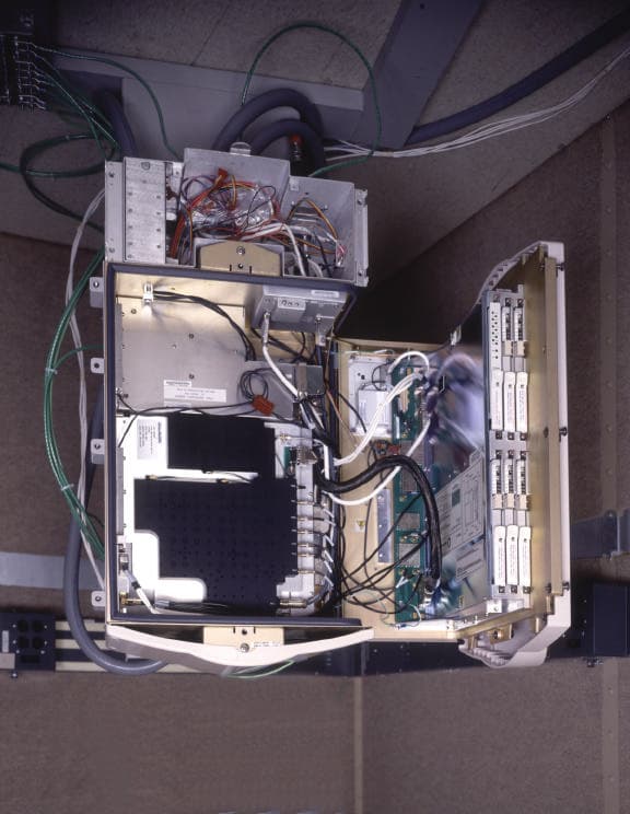
Click to zoom
Application Details
- Equipment Class
- TNB - Licensed Non-Broadcast Station Transmitter
- Date of Grant
- Sep 12, 1999
- Application Purpose
- Original Equipment
- Date of Application
- Jun 03, 1999
- Equipment Note
- FLEXENT PCS-TDMA Microcell
- Frequency Range
- 1930.08000000 - 1989.96000000
- Company
- Nokia of America Corporation
- Country
- United States
Documents & Files
Document Text
Text extracted from the exhibit documents filed with the FCC. Open a document above to read the original.
Attestation Statements
APPLICANT: Lucent TechnologiesFCC ID: AS5CMP-30 EXHIBIT 1 Section 2.911(d) CERTIFICATION OF BASE STATION EQUIPMENT June 3, 1999 To Whom It May Concern: This is to certify that the FLEXENT PCS Dual Radio Module (DRM), TDMA base station transceiver manufactured by Lucent Technologies under FCC ID: AS5CMP-30, was designed and developed in accordance with the guidelines of TIA/EIA/IS-136.2-A (October 1996): TDMA Cellular/PCS – Radio Interface – Mobile Station – Base Station Compatibility – Traffic Channels and FSK Control Channel ; TIA/EIA/IS-138-A (July 1996): TDMA Cellular/PCS – Radio Interface – Minimum Performance Standards for Base Stations; and ANSI J-STD-010-1996: PCS IS-136 Based Base Station – Minimum Performance 1900 MHz Standard. The PCS-DRM is also compliant with the requirements of the Code of Federal regulations (CFR), Title 47, Part 24, Subpart E – Broadband PCS. R. J. Pillmeier Technical Manager Certification Test Group Section 2.911(d) QUALIFICATION OF ENGINEERS Mr. Michael P. Farina, Member of Technical Staff, has been an employee of Lucent Technologies (formerly AT&T Corp.) since August 1960. In addition to his numerous prior submittals to the Commission, he has extensive experience in the development and testing of a variety of telecommunications products, many requiring compliance with Underwriters Laboratories Standards. He has also made numerous prior submittals to Industry Canada, Certification and Engineering Bureau, for Radio equipment Certification. His qualifications are further supported by his advanced academic experience (MSEE). R. J. Pillmeier Technical Manager Certification Test Group Section 2.911(d) CERTIFICATION OF TECHNICAL TEST DATA I hereby certify that the technical test data are the results of tests either performed or supervised by me. Michael P. Farina Member of Technical Staff Certification Test Group
Block Diagram
APPLICANT: Lucent TechnologiesFCC ID: AS5CMP-30 EXHIBIT 22 EQUIPMENT BLOCK DIAGRAM FLEXENT PCS-TDMA Microcell J41698A-1 Multi Carrier Linear Amplifier AS5CMP-31 Duplex Tx/Rx 60 MHz Bandpass Filter Back Plane 5 PDRMs AS5CMP-30 PCU TOMTRC AC Power 115 Vac Tx/Rx0 Antenna TOM: TDMA Oscillator Module TRC: TDMA Radio Controller PCU: Power Conversion Unit PDRM: PCS-TDMA Dual Radio Module Transceiver LNA: Low Noise Amplifier (receive) I/O Module LNA Rx1 Antenna
Cover Letter(s)
Lucent Technologies Inc. 67 Whippany Road Whippany, NJ 07981 June 3, 1999 Office of Engineering and Technology Authorization and Evaluation Division Equipment Authorization Branch 7435 Oakland Mills Road Columbia, Maryland 21046 Re: Application for Certification of FCC ID: AS5CMP-30 Dear Examiner: In accordance with Parts 2 and 24 of the Commission’s Rules and Regulations, we are submitting herewith statements and supporting data to show compliance with the requirements of the Commission for certification of the Lucent Technologies FLEXENT PCS Dual Radio Module (PDRM), Part No. 44WR53, under FCC ID: AS5CMP-30. The PDRM transceiver utilizes Time Domain Multiple Access (TDMA) technology, using the standard π/4 DQPSK modulation for 3 time slots. The PDRM can transmit 1 or 2 carriers; each carrier can be tuned independently across the PCS frequency band 1930.08-1989.96 MHz with individual power level control, under external software control. This transceiver was designed to operate in the FLEXENT PCS-TDMA Microcell J41698A-1 base station equipment frame, in combination with the PCS Multi Carrier Linear Amplifier (PMCLA), Part No. 44WA28, which will be filed separately under AS5CMP-31, and with duplexed Tx/Rx 60 MHz bandpass filter.. The data summarized below is in the form presently used by the Commission’s Radio Equipment List, Equipment Acceptable for Licensing. ManufacturerLucent Technologies, Columbus, Ohio Equipment IdentificationAS5CMP-30 Rules Part NumberPart 24, Subpart E – Broadband PCS Frequency RangeTransmit 1930.08-1989.96 MHz Receive 1850.04-1909.92 MHz Output Power+ 15.5 dBm (35.5 mW) per carrier maximum to – 41.0 dBm per carrier minimum Frequency Tolerance± 1.5 ppm Emission Designator40K0GXW The PCS-DRM, under AS5CMP-30, was designed in accordance with the guidelines of TIA/EIA/IS- 136.2-A (October 1996): TDMA Cellular/PCS – Radio Interface – Mobile Station – Base Station Compatibility – Traffic Channels and FSK Control Channel ; TIA/EIA/IS-138-A (July 1996): TDMA Cellular/PCS – Radio Interface – Minimum Performance Standards for Base Stations; and ANSI J-STD- 010-1996: PCS IS-136 Based Base Station – Minimum Performance 1900 MHz Standard. Attached are the FCC Form 731 (Application for Equipment Authorization – Radio Frequency Devices) and the required measurement data and exhibits. These exhibits contain the technical requirements, and the required statements and documents for equipment authorization. The technical contact at Lucent Technologies will comply with any request for additional information should the need arise. Lucent Technologies has requested that the following exhibits be considered confidential: Exhibit 4 FLEXENT TDMA Microcell: Operation, Administration, and Maintenance Manual Exhibit 6 Schematic Diagrams Exhibit 7 Description of Circuitry for Determing and Stabilizing Frequency Exhibit 9 Description of Circuitry for Limiting Modulation and Limiting Power The letter of request is attached and the required fees are submitted as required for electronic filing. Sincerely, R. J. Pillmeier Technical Manager Certification Test Group Att. Transmitter Certification Report
Cover Letter(s)
Lucent Technologies Inc. 67 Whippany Road Whippany, NJ 07981 June 3, 1999 Office of Engineering and Technology Authorization and Evaluation Division Equipment Authorization Branch 7435 Oakland Mills Road Columbia, Maryland 21046 Re: REQUEST FOR CONFIDENTIALITY for FCC ID: AS5CMP-30 Dear Examiner: On behalf of Lucent Technologies, I hereby request that the following exhibits, included in the Application for Certification for FCC ID: AS5CMP-30, be maintained as confidential information and not be made available for public inspection at any time. Exhibit 4 FLEXENT TDMA Microcell: Operation, Administration, and Maintenance Manual Exhibit 6 Schematic Diagrams Exhibit 7 Description of Circuitry for Determing and Stabilizing Frequency Exhibit 9 Description of Circuitry for Limiting Modulation and Limiting Power These exhibits contain Lucent Technologies proprietary information that is considered to be trade secrets, with possible patents pending, and the property of Lucent Technologies, pursuant to the provisions of Part 0.457(d) of the Commission’s Rules. The FLEXENT TDMA Microcell Operation, Administration, and Maintenance Manual, included in Exhibit 4, is not furnished to the user, except under very exceptional and very limited circumstances. This manual contains highly proprietary circuit, equipment and architecture descriptions that must not be made available for public inspection. The cover/title page is explicitly labeled “Unpublished and Not for Publication”. A copy is included in the electronic folder labeled confidential. Thank you for your consideration in this matter. Sincerely, Michael P. Farina Member of Technical Staff Certification Test Group Phone: 973-386-4344 FAX: 973-386-5384
Cover Letter(s)
Lucent Technologies Inc. 67 Whippany Road Whippany, NJ 07981 June 8, 1999 Office of Engineering and Technology Authorization and Evaluation Division Equipment Authorization Branch 7435 Oakland Mills Road Columbia, Maryland 21046 Re: Application for Certification of FCC ID: AS5CMP-30 Confirmation Number: EA94431 Date of Submission: 06/04/1999 Dear Examiner: Please change Form 731, Item 12, “Rated RF Power Output” from 1.2 watts to .036 watts. This request was previously submitted to B. Taube, via e-mail dated “Tue, 08 Jun 1999”. Thank you for your consideration in this matter. Sincerely, Michael P. Farina Member of Technical Staff Certification Test Group Phone: 973-386-4344 FAX: 973-386-5384 E-Mail: [email protected]
ID Label/Location Info
APPLICANT: Lucent TechnologiesFCC ID: AS5CMP-30 EXHIBIT 10 Section 2.1033 (c)(11) Equipment identification label. The equipment label to be affixed to the FLEXENT PCS-TDMA Dual Radio Module transceiver, 44WR53, will contain the following information. The engineering drawing of the label is attached to this exhibit. Lucent Technologies FLEXENT Transceiver PART NO: 44WR53 FCC ID: AS5CMP-30 Dual Radio Module transceiver 44WR53 flfl REAR LEFT SIDE FRONT ‡‡ APPLICANT: Lucent TechnologiesFCC ID: AS5CMP-30 EXHIBIT 10 Engineering Drawing of the equipment label to be displayed on the PCS-TDMA Dual Radio Module (PDRM) 44WR53, FCC ID: AS5CMP-30. APPLICANT: Lucent TechnologiesFCC ID: AS5CMP-30 EXHIBIT 10 Section 2.1033 (c)(12): PHOTOGRAPHS OF THE EQUIPMENT. FLEXENT PCS-TDMA Microcell J41698A-1: Front and Right Side View AS5CMP-30 Label Placement
Internal Photos
1 APPLICANT: Lucent TechnologiesFCC ID: AS5CMP-30 EXHIBIT 11 Section 2.1033 (c)(12): PHOTOGRAPHS OF THE EQUIPMENT. FLEXENT PCS-TDMA Microcell J41698A-1: Front and Right Side View . 2 APPLICANT: Lucent TechnologiesFCC ID: AS5CMP-30 EXHIBIT 11 Section 2.1033 (c)(12): PHOTOGRAPHS OF THE EQUIPMENT. FLEXENT PCS-TDMA Microcell J41698A-1: Interior View Showing Duplex Transmit Filter 3 APPLICANT: Lucent TechnologiesFCC ID: AS5CMP-30 EXHIBIT 11 Section 2.1033 (c)(12): PHOTOGRAPHS OF THE EQUIPMENT. FLEXENT PCS-TDMA Microcell J41698A-1: Interior View Showing Radio Shelf and TOM 4 APPLICANT: Lucent TechnologiesFCC ID: AS5CMP-30 EXHIBIT 11 Section 2.1033 (c)(12): PHOTOGRAPHS OF THE EQUIPMENT. FLEXENT PCS-TDMA Microcell J41698A-1: Primary Distribution Cabinet 5 APPLICANT: Lucent TechnologiesFCC ID: AS5CMP-30 EXHIBIT 11 Section 2.1033 (c)(12): PHOTOGRAPHS OF THE EQUIPMENT. FLEXENT PCS-TDMA Microcell J41698A-1: Primary Distribution Cabinet Interior View 6 APPLICANT: Lucent TechnologiesFCC ID: AS5CMP-30 EXHIBIT 11 Section 2.1033 (c)(12): PHOTOGRAPHS OF THE EQUIPMENT. PCS-TDMA Dual Radio Module 44WR53: Front and Left Side View 7 APPLICANT: Lucent TechnologiesFCC ID: AS5CMP-30 EXHIBIT 11 Section 2.1033 (c)(12): PHOTOGRAPHS OF THE EQUIPMENT. FLEXENT PCS-TDMA Microcell J41698A-1: Front and Right Side View AS5CMP-30 Label Placement 8 APPLICANT: Lucent TechnologiesFCC ID: AS5CMP-30 EXHIBIT 11 Section 2.1033 (c)(12): PHOTOGRAPHS OF THE EQUIPMENT. PCS-TDMA Dual Radio Module 44WR53: Circuit Board View 9 APPLICANT: Lucent TechnologiesFCC ID: AS5CMP-30 EXHIBIT 11 Section 2.1033 (c)(12): PHOTOGRAPHS OF THE EQUIPMENT. PCS-TDMA Dual Radio Module 44WR53: Rear and Left Side View 10 APPLICANT: Lucent TechnologiesFCC ID: AS5CMP-30 EXHIBIT 11 Section 2.1033 (c)(12): PHOTOGRAPHS OF THE EQUIPMENT. FLEXENT TDMA Oscillator Module (TOM) 11 APPLICANT: Lucent TechnologiesFCC ID: AS5CMP-30 EXHIBIT 11 Section 2.1033 (c)(12): PHOTOGRAPHS OF THE EQUIPMENT. FLEXENT TDMA Oscillator Module (TOM): Circuit Board View 12
Operational Description
APPLICANT: Lucent TechnologiesFCC ID: AS5CMP-30 EXHIBIT 3 Section 2.1033 (c)(1) The full name and mailing address of the manufacturer of the device and the applicant for certification. Manufacturer:Lucent Technologies Columbus Manufacturing Facility 6200 East Broad Street, Columbus, Ohio 43213 Applicant:Lucent Technologies 600 Mountain Avenue, Murray Hill, NJ 07974 Attention: Jane M. Zakutansky Section 2.1033(c)(2) FCC Identifier:AS5CMP-30 Section 2.1033(c)(4) Type or types of emission:40K0GXW Section 2.1033(c)(5) Frequency range:Transmit: 1930.080 – 1989.960 MHz Receive: 1850.010 – 1909.920 MHz Section 2.1033(c)(6) Range of operating power values or specific operating power levels, and description of any means provided for variation of operating power. The FLEXENT PCS-TDMA Microcell J416698A-1, which incorporates the 44WR53 PCS Dual Radio Module (PDRM), subject of this application for certification under AS5CMP-30, and the 44WA28 PCS Multi Carrier Linear Amplifier (PMCLA), subject of a separate application for certification under AS5CMP-31, is designed to provide 1.2 W (30.8 dBm) per carrier at the transmit antenna terminal and a total composite power of 12.0 W (40.8 dBm) for the rated 10 carrier capability. The Microcell incorporates 5 PDRM transceivers and 1 PMCLA. Each PDRM can transmit 1 or 2 carriers with a maximum power level at the PDRM transmit terminal of + 15.5 dBm (35.5 mW) per carrier, corresponding to total composite power level of + 18.5 dBm (71 mW) per 2 carriers. The PDRM carrier frequency and power level is software controlled by an external Remote Maintenance Terminal (RMT). The power level of each PDRM carrier is continuously adjustable from a maximum of + 15.5 dBm to a minimum of – 41 dBm with a resolution of 0.1 dBm. The controlling software utilizes a calibration table, which controls a voltage-controlled attenuator. Section 2.1033(c)(7) Maximum power rating as defined in the applicable part (s) of the rules. The maximum power rating of the 44WR53 PCS Dual Radio Module, subject of this application under AS5CMP-30, is + 15.5 dBm (35.5 mW) per carrier, which corresponds to a total composite power level of +18.5 dBm (71 mW) for 2 carriers. The complete FLEXENT PCS-TDMA Microcell J41698A-1, incorporating the PDRM (AS5CMP-30), the PMCLA (AS5CMP-31) and the duplex transmit/receive (TxDx) bandpass filter is rated at 1.2 W (30.8 dBm) per carrier at the transmit antenna terminal, corresponding to a total composite power level of 12 W (40.8 dBm) for 10 carriers.
Operational Description
APPLICANT: Lucent TechnologiesFCC ID: AS5CMP-30 EXHIBIT 7 Section 2.1033 (c)(10) A description of all circuitry and devices for determining and stabilizing frequency. EXHIBIT 7 IS REQUESTED TO BE HELD CONFIDENTIAL AND NOT BE MADE AVAILABLE FOR PUBLIC INSPECTION AT ANY TIME
Operational Description
APPLICANT: Lucent TechnologiesFCC ID: AS5CMP-30 EXHIBIT 8 Section 2.1033 (c)(10): Description of circuitry and devices for suppression of spurious radiation. Spurious emissions radiated from the FLEXENT PCS-TDMA Microcell J41698A-1 are suppressed by implementing sound Electromagnetic Compatibility (EMC) design practices extending from the circuit board level to the system level: 1) RF shielding on coaxial cables, 2) RF shielding “cans” mounted on the circuit packs, 3) effective grounding, 4) effective RF gasket mounted to the equipment door frame, 4) EMI filter on the AC power leads, and 5) effective 60 MHz duplex transmit and receive (TxDx or TxRx0) bandpass filter plus one 60 MHz simplex receive (Rx1) bandpass filter for diversity receive as described below. The filter characteristic plots are attached to this exhibit. A filter panel in a duplex configuration supports a single antenna for both reception and transmission as shown in the figure below. Since there is no physical separation of the antennas in simplex configurations, the transmit path's receive band attenuation must be at least 20 dB greater than the simplex path. Each duplex panel also supports diversity receive, so each panel has two independent paths- one duplexed transmit/receive path and separate receive path. Additionally, each of the two antenna ports contains a 30.0dB/ 30.0 dB bi-directional coupler for diagnostics. The 60 MHz bandpass filters are passive devices and are realized by tuned cavities. TX RX0 RX1 APPLICANT: Lucent TechnologiesFCC ID: AS5CMP-30 EXHIBIT 8 FILTER CHARACTERISTIC PLOTS: Duplex 60 MHz Transmit Bandpass Filter APPLICANT: Lucent TechnologiesFCC ID: AS5CMP-30 EXHIBIT 8 FILTER CHARACTERISTIC PLOTS: Duplex 60 MHz Receive Bandpass Filter APPLICANT: Lucent TechnologiesFCC ID: AS5CMP-30 EXHIBIT 8 FILTER CHARACTERISTIC PLOTS: Simplex 60 MHz Receive Bandpass Filter
Operational Description
APPLICANT: Lucent TechnologiesFCC ID: AS5CMP-30 EXHIBIT 12 Section 2.1033 (c)(13) Description of the modulation system. The TDMA Dual Radio Module transceiver (44wr53) is a single board circuit pack containing both digital and RF circuits which make up two complete dual-mode transceivers. Basic modulation is performed by an ASIC designed for generating analog π/4DQPSK baseband I and Q quadrature modulator signals. A detailed description is contained in Exhibit 9.
Test Report
APPLICANT: Lucent TechnologiesFCC ID: AS5CMP-30 TABLE OF CONTENTS Exhibit 1Section 2.911(d)Qualifications and Certifications Exhibit 2PCS Requirement Human Exposure Compliance Statement Exhibit 3Section 2.1033(c)(1,2,4-7)Manufacturer , Applicant , Identifier, Emission, Frequency Range, Operating Power Values and Maximum Power Rating Exhibit 4Section 2.1033(c)(3)Installation and Operating Instructions ‡‡ CONFIDENTIAL CONFIDENTIAL Exhibit 5Section 2.1033(c)(8-9)DC Voltages and Currents; Tune-up Procedure Exhibit 6Section 2.1033(c)(10)Schematic Diagrams ‡‡ CONFIDENTIAL CONFIDENTIAL Exhibit 7Section 2.1033(c)(10)Description of Circuitry for Determining and Stabilizing CONFIDENTIALFrequency ‡‡ CONFIDENTIAL Exhibit 8Section 2.1033(c)(10)Description of Circuitry and Devices for Suppression of Spurious Radiation Exhibit 9Section 2.1033(c)(10)Description of Circuitry and Devices for Limiting Modulation, CONFIDENTIALand for Limiting Power. ‡‡ CONFIDENTIAL Exhibit 10Section 2.1033(c)(11)Equipment Identification Label. Exhibit 11Section 2.1033(c)(12)Photographs of the Equipment Exhibit 12Section 2.1033(c)(13)Description of the Digital Modulation System Exhibit 13Section 2.1033(c)(14)Required Measurement Data Exhibit 14Section 2.1046Measurements Required: RF Power Output Exhibit 15Section 2.1047Measurements Required: Modulation Characteristics Exhibit 16Section 2.1049Measurements Required: Occupied Bandwidth Exhibit 17Section 2.1051Measurements Required: Spurious Emissions at Antenna Terminal Exhibit 18Section 2.1053Measurements Required: Field Strength of Spurious Radiation Exhibit 19Section 2.1055Measurements Required: Frequency Stability Exhibit 20Special TestMeasurements Required: Two-Tone Intermodulation Product Suppression Exhibit 21Section 2.947(d)Listing of Test Equipment Used Exhibit 22Equipment Block Diagram
Test Report
APPLICANT: Lucent TechnologiesFCC ID: AS5CMP-30 EXHIBIT 13 Section 2.1033 (c)(14) The required measurement data is presented in the following exhibits as follows: Exhibit 14Section 2.1046Measurements Required: RF Power Output Exhibit 15Section 2.1047Measurements Required: Modulation Characteristics Exhibit 16Section 2.1049Measurements Required: Occupied Bandwidth Exhibit 17Section 2.1051Measurements Required: Spurious Emissions at Antenna Terminal Exhibit 18Section 2.1053Measurements Required: Field Strength of Spurious Radiation Exhibit 19Section 2.1055Measurements Required: Frequency Stability Exhibit 20Special TestMeasurements Required: Two-Tone Intermodulation Product Suppression
Test Report
APPLICANT: Lucent TechnologiesFCC ID: AS5CMP-30 EXHIBIT 14 Section 2.1046 Measurement s Required: RF Power Output This test procedure is a measurement of the single channel RF power transmitted at the PCS-TDMA Dual Radio Module (PDRM) output terminal as shown in the accompanying test set-up diagram. In accordance with ANSI J-STD-010-1996, Section 3.2, the power level shall be maintained within +1 to –3 dB of the manufacturer’s rated single channel value across the PCS frequency band 1930.08 – 1989.96 MHz. A single channel was tuned to the center frequency of B-Block, channel 917 at 1957.53 MHz, and the power level set to approximately +15.5 dBm at the PDRM Tx terminal. The carrier was then tuned to 3 frequencies in each PCS Block, corresponding to the lower block edge (le), block center frequency (cf) and the upper edge frequency (ue), and the corresponding power level measured. PCS Block PCS Ch. No. PCS Freq. MHz PDRM Output dBm A(le)21930.08+14.8 A(cf)2501937.52+15.0 A(ue)4981944.96+15.0 D(le)5021945.08+15.0 D(cf)5831947.51+14.9 D(ue)6651949.97+14.8 B(le)6681950.06+14.9 B(cf)9171957.53+14.9 B(ue)11651964.97+14.9 E(le)11681965.06+15.1 E(cf)12501967.52+15.3 E(ue)13321969.98+14.9 F(le)13351970.07+15.0 F(cf)14171972.53+14.9 F(ue)14981974.96+14.8 C(le)15021975.08+15.0 C(cf)17501982.52+15.0 C(ue)19981989.96+14.3 Results: Power measurements were made with a Hewlett-Packard E4419A, EPM Series Power Meter and an HP ECP-E18A CW Power Sensor. All measurements are within the required +1 to –3 dB of the rated +15.5 dBm maximum power output. APPLICANT: Lucent TechnologiesFCC ID: AS5CMP-30 EXHIBIT 14 Test set-up for measuring the power output from the PCS-TDMA Dual Radio Module transceiver. FLEXENT PCS-TDMA Microcell J41698A-1 TOM: TDMA Oscillator Module TRC: TDMA Radio Controller PCU: Power Conversion Unit PDRM: PCS-TDMA Dual Radio Module LISN: Line Impedance Stabilization Network Duplex Tx/Dx Bandpass Filter 60 MHz PCS Multi Carrier Linear Amplifier (PMCLA) AS5CMP-31 Backplane Nominal 13 dB Attenuation PDRM AS5CMP-30 TOM TRC PCU Power Meter LISN AC Utility Power Line 115Vac
Test Report
APPLICANT: Lucent TechnologiesFCC ID: AS5CMP-30 EXHIBIT 15 Section 2.1047 Measurements Required: Modulation Characteristics The TDMA modulation utilized by the PCS-TDMA Dual Radio Module (PDRM), 44WR53, is the standard π/4 differentially encoded quadrature phase shift keying (π/4 DQPSK). The modulation accuracy measurements were performed with all 3 TDMA time slots modulated with a pseudo-random bit stream. Measurements were made at the PDRM output terminal on the backplane, with PDRM tuned to 1) the lowest settable PCS channel: A-Block Ch 2 1930.08 MHz, 2) mid PCS Band: B-Block Ch 917 1957.53 MHz, and 3) the highest settable PCS channel: C-Block Ch 1998 1989.96 MHz. The required modulation accuracy is specified in TIA/EIA/IS-138-A, July 1996, Section 3.3.2 Digital and in ANSI J-STD-010-1996, Section 3.3 Modulation Requirements. The “minimum standard”, or limitation, is stated that the RMS error vector magnitude shall be less than 12.5%. Measurements were made with a Rohde & Schwarz Spectrum Analyzer 20 Hz to 26.5 GHz FSEM, Model 1079.8500.30, calibrated as required for ISO-9001 compliance. The measurement results and test set-up block diagram are included. RESULTS: The measurement data below demonstrates that the PCS-TDMA Dual Radio Module (PDRM), 44WR53, is in full compliance with the modulation accuracy requirements specified in TIA/EIA/IS-138-A and in ANSI J-STD-010-1996. The error vector magnitude is less than 12.5% across the PCS Frequency Band 1930.08 – 1989.96 MHz. Modulation Accuracy: PCS-TDMA Dual Radio Module (PDRM), 44WR53, output tuned to A-Block Channel 2, 1930.08 MHz Error Vector Magnitude = 3.37% rms APPLICANT: Lucent TechnologiesFCC ID: AS5CMP-30 EXHIBIT 15 Modulation Accuracy: PCS-TDMA Dual Radio Module (PDRM), 44WR53, output tuned to B-Block Channel 917, 1957.53 MHz Error Vector Magnitude = 3.46% rms Modulation Accuracy: PCS-TDMA Dual Radio Module (PDRM), 44WR53, output tuned to C-Block Channel 2, 1989.96 MHz Error Vector Magnitude = 3.48% rms APPLICANT: Lucent TechnologiesFCC ID: AS5CMP-30 EXHIBIT 15 Test set-up for measuring the modulation accuracy of the PCS-TDMA Dual Radio Module transceiver. FLEXENT PCS-TDMA Microcell J41698A-1 Duplex Tx/Dx Bandpass Filter 60 MHz PCS Multi Carrier Linear Amplifier (PMCLA) AS5CMP-31 Backplane Nominal 13 dB Attenuation PDRM AS5CMP-30 TOM TRC PCU Rohde & Schwarz Spectrum Analyzer FSEM 20 Hz – 26.5 GHz AC Utility Power Line 115Vac LISN TOM: TDMA Oscillator Module TRC: TDMA Radio Controller PCU: Power Conversion Unit PDRM: PCS-TDMA Dual Radio Module LISN: Line Impedance Stabilization Network
Test Report
APPLICANT: Lucent TechnologiesFCC ID: AS5CMP-30 EXHIBIT 16 Section 2.1049 Measurements Required: Occupied Bandwidth In compliance with Section 2.1049(h), a single TDMA carrier was modulated by a pseudo-random data bit stream for all 3 time slots, and the PCS-TDMA Dual Radio Module (PDRM) output power level set to approximately +15.5 dBm at it’s output terminal. In compliance with Part 24.238(c), occupied bandwidth measurements were made at both the lower and the upper block edge for each PCS frequency block as follows: PCS Frequency Block PCS Channel No. Carrier Center Frequency - MHz A (le)21930.08 A (ue)4981944.96 D (le)5021945.08 D (ue)6651949.97 B (le)6681950.06 B (ue)11651964.97 E (le)11681965.06 E (ue)13321969.98 F (le)13351970.07 F (ue)14981974.96 C (le)15021975.08 C (ue)19981989.96 le = lower block edge frequency; and ue = upper block edge frequency The occupied bandwidth limitations and emission mask for a 30 kHz TDMA carrier, i.e., digital transceiver, is specified in Part 22.917(d)(1-3) as: Displacement from the Carrier Center Frequency Required Attenuation Below the Carrier Greater than 20 kHz up to 45 kHzAt least 26 dBc Greater than 45 kHz up to 90 kHzAt least 45 dBc Greater than 90 kHz up to 1 st harmonicAt least 60 dBc Or 43 + 10 log (Carrier Power in Watts) dBc Or whichever is the lesser attenuation The limitation for each PCS frequency block edge is specified in Part 24.238(a) as: “ the power of any emission shall be attenuated below the transmitter power (P in Watts) by at least 43 + 10 log (P) dBc.” For the PDRM output power at +15.5 dBm (35.5 mW), the required block edge emission attenuation is then 28.5 dBc. Part 24.238(b) specifies that the measurement instrumentation resolution bandwidth be set to 1% of the fundamental emission bandwidth. For the 30 kHz TDMA carrier, the spectrum analyzer resolution bandwidth was set to 300 Hz. The standard measurement procedure is to align the center of the carrier with the top of the spectrum analyzer display reticle (i.e., 0 dBm) and reference required “attenuation below the carrier” to the 0 dBm reference. Attenuation below the carrier is then read directly off the 0 dBm to -110 dBm scale. Using the 300 Hz resolution bandwidth requires displacing (offsetting) the 30 kHz modulated carrier from the 0 dBm reference line by: 10 log (carrier bandwidth/instrumentation resolution bandwidth) 10 log (30 kHz/300 Hz) = 20 dB offset APPLICANT: Lucent TechnologiesFCC ID: AS5CMP-30 EXHIBIT 16 RESULTS: The attached occupied bandwidth plots demonstrate full compliance with the requirements of Part 24.238, for the required frequencies specified above. The block edge limitation of 28.5 dBc, for a carrier power level of +15.5 dBm, is less stringent than the 45 dBc emission mask. On this basis, and that all carriers are well within the required emission mask, the PCS-TDMA Dual Radio Module (PDRM), 44WR53, demonstrated full compliance with Part 24.238 for occupied bandwidth requirements. Test set-up for measuring the occupied bandwidth of the PCS-TDMA Dual Radio Module transceiver. FLEXENT PCS-TDMA Microcell J41698A-1 Duplex Tx/Dx Bandpass Filter 60 MHz PCS Multi Carrier Linear Amplifier (PMCLA) AS5CMP-31 Backplane Nominal 13 dB Attenuation PDRM AS5CMP-30 TOM TRC PCU HP 8495B Attenuator/70 dB variable HP 8494B Attenuator/11 dB variable Rohde & Schwarz EMI Test Receiver ESMI 20 Hz – 26.5 GHz LISN AC Utility Power Line 115Vac TOM: TDMA Oscillator Module TRC: TDMA Radio Controller PCU: Power Conversion Unit PDRM: PCS-TDMA Dual Radio Module LISN: Line Impedance Stabilization Network APPLICANT: Lucent TechnologiesFCC ID: AS5CMP-30 EXHIBIT 16 OCCUPIED BANDWIDTH PLOTS: PCS A-Block: Lower Edge Channel Channel 2, 1930.08 MHz PCS-TDMA Dual Radio Module transceiver output APPLICANT: Lucent TechnologiesFCC ID: AS5CMP-30 EXHIBIT 16 OCCUPIED BANDWIDTH PLOTS: PCS A-Block: Upper Edge Channel Channel 498, 1944.96 MHz PCS-TDMA Dual Radio Module transceiver output APPLICANT: Lucent TechnologiesFCC ID: AS5CMP-30 EXHIBIT 16 OCCUPIED BANDWIDTH PLOTS: PCS D-Block: Lower Edge Channel Channel 502, 1945.08MHz PCS-TDMA Dual Radio Module transceiver output APPLICANT: Lucent TechnologiesFCC ID: AS5CMP-30 EXHIBIT 16 OCCUPIED BANDWIDTH PLOTS: PCS D-Block: Upper Edge Channel Channel 665, 1949.97 MHz PCS-TDMA Dual Radio Module transceiver output APPLICANT: Lucent TechnologiesFCC ID: AS5CMP-30 EXHIBIT 16 OCCUPIED BANDWIDTH PLOTS: PCS B-Block: Lower Edge Channel Channel 668, 1950.06 MHz PCS-TDMA Dual Radio Module transceiver output APPLICANT: Lucent TechnologiesFCC ID: AS5CMP-30 EXHIBIT 16 OCCUPIED BANDWIDTH PLOTS: PCS B-Block: Upper Edge Channel Channel 1165, 1964.97 MHz PCS-TDMA Dual Radio Module transceiver output APPLICANT: Lucent TechnologiesFCC ID: AS5CMP-30 EXHIBIT 16 OCCUPIED BANDWIDTH PLOTS: PCS E-Block: Lower Edge Channel Channel 1168, 1965.06 MHz PCS-TDMA Dual Radio Module transceiver output APPLICANT: Lucent TechnologiesFCC ID: AS5CMP-30 EXHIBIT 16 OCCUPIED BANDWIDTH PLOTS: PCS E-Block: Upper Edge Channel Channel 1332, 1969.98 MHz PCS-TDMA Dual Radio Module transceiver output APPLICANT: Lucent TechnologiesFCC ID: AS5CMP-30 EXHIBIT 16 OCCUPIED BANDWIDTH PLOTS: PCS F-Block: Lower Edge Channel Channel 1335, 1970.07 MHz PCS-TDMA Dual Radio Module transceiver output APPLICANT: Lucent TechnologiesFCC ID: AS5CMP-30 EXHIBIT 16 OCCUPIED BANDWIDTH PLOTS: PCS F-Block: Upper Edge Channel Channel 1498, 1974.96 MHz PCS-TDMA Dual Radio Module transceiver output APPLICANT: Lucent TechnologiesFCC ID: AS5CMP-30 EXHIBIT 16 OCCUPIED BANDWIDTH PLOTS: PCS C-Block: Lower Edge Channel Channel 1502, 1975.08 MHz PCS-TDMA Dual Radio Module transceiver output APPLICANT: Lucent TechnologiesFCC ID: AS5CMP-30 EXHIBIT 16 OCCUPIED BANDWIDTH PLOTS: PCS C-Block: Upper Edge Channel Channel 1998, 1989.96 MHz PCS-TDMA Dual Radio Module transceiver output
Test Report
APPLICANT: Lucent TechnologiesFCC ID: AS5CMP-30 EXHIBIT 17 Section 2.1051 Measurements Required: Spurious Emissions at Antenna Terminal Spurious emissions conducted to the transmit terminal of the PCS-TDMA Dual Radio Module (PDRM) were investigated from the lowest RF frequency , 15 MHz, to the 10 th harmonic of the carrier, 20 GHz, as required by Part 2.1057(a)(1). Part 2.1057(c) specifies that spurious emissions attenuated more than 20 dB below the required limitation do not need to be reported. A single TDMA carrier was modulated by a pseudo-random data bit stream for all 3 time slots, and the PCS-TDMA Dual Radio Module (PDRM) output power level set to approximately +15.5 dBm at it’s output terminal. In compliance with Part 24.238(c), conducted spurious emission measurements were made at both the lower and the upper block edge for each PCS frequency block as follows: PCS Frequency Block PCS Channel No. Carrier Center Frequency - MHz A (le)21930.08 A (ue)4981944.96 D (le)502194…
Text truncated - open the document above for the full version.
Contact Information
Applicant
Raymond J. Johnson(Technical Manager)
Technical Contact
Lucent TechnologiesR. J Pillmeier
[email protected]973-386-3837
67 Whippany Road · Whippany, New Jersey · United States
Technical Specifications
| # | Rule Parts | Frequency Range | Power Output | Emission | Tolerance |
|---|---|---|---|---|---|
| 1 | 24E | 1.93 GHz - 1.99 GHz | 36.00 mW | 40K0DXW | 1.5000000000 ppm |
Other Applications from Nokia of America Corporation

AS5BBTRX-23
Mar 15, 2015B13 RRH 4X30
Equipment Class
TNB - Licensed Non-Broadcast Station Transmitter
AS5BBTRX-21
Feb 01, 2015PCS LTE 9764 Metro Cell Outdoor Transceiver System
Equipment Class
PCB - PCS Licensed Transmitter
AS5BBTRX-22
Jan 26, 2015B25 RRH 4X30
Equipment Class
PCB - PCS Licensed Transmitter
AS5BBTRX-17
Jan 08, 2014AWS LTE 9764 Metro Cell Outdoor Transceiver System
Equipment Class
TNB - Licensed Non-Broadcast Station Transmitter
AS5BBTRX-14
Dec 18, 20139763 MCI B25 PCS LTE 2x250mW
Equipment Class
PCB - PCS Licensed Transmitter