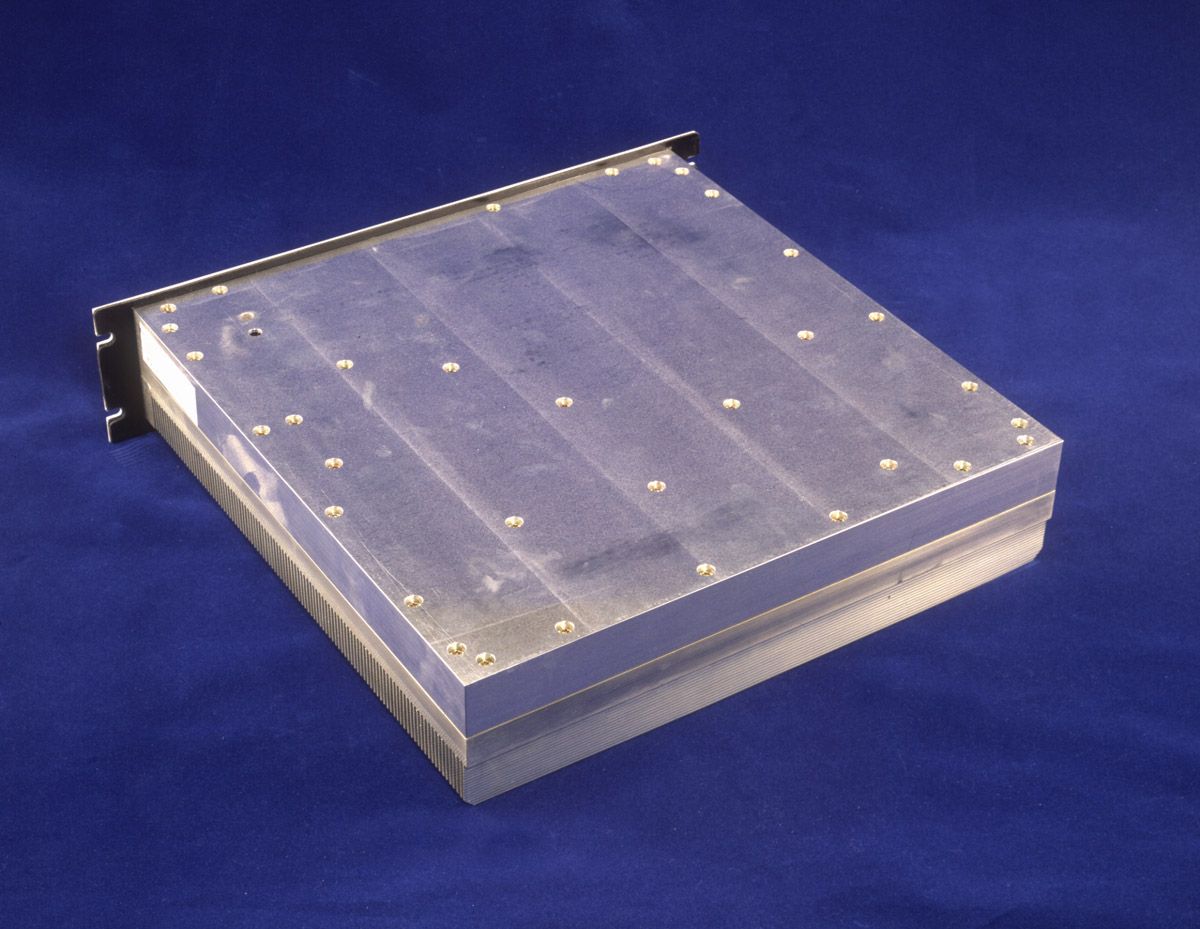
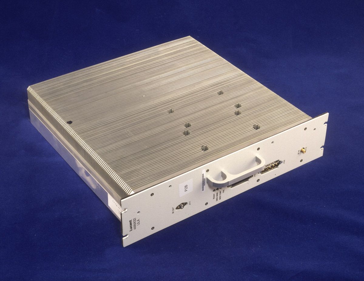
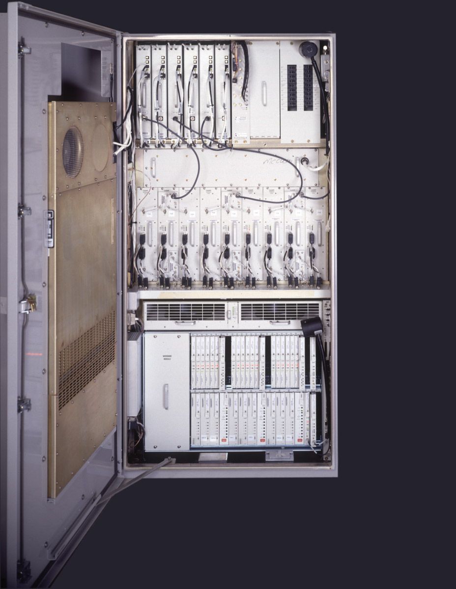
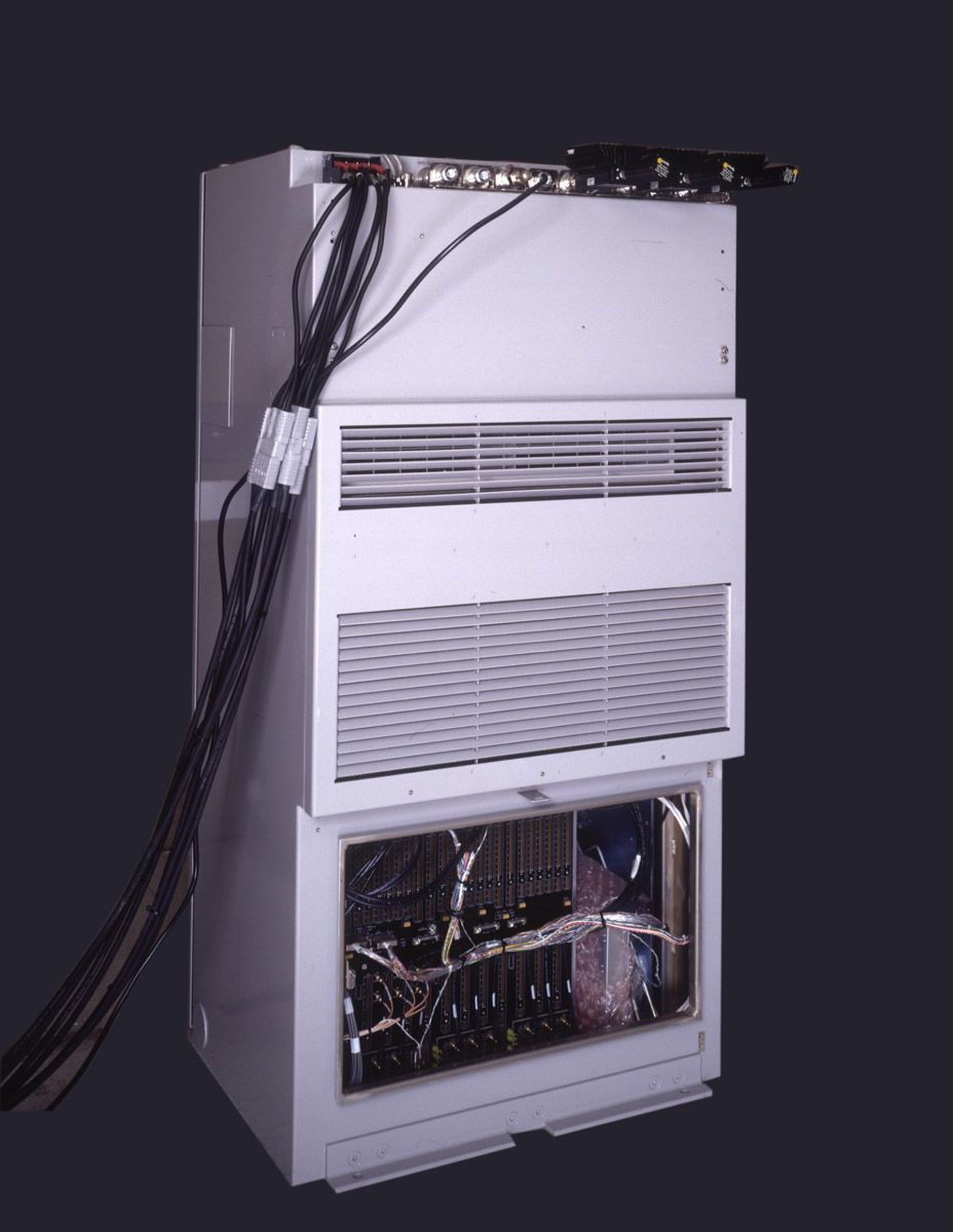
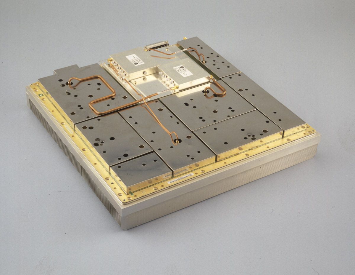
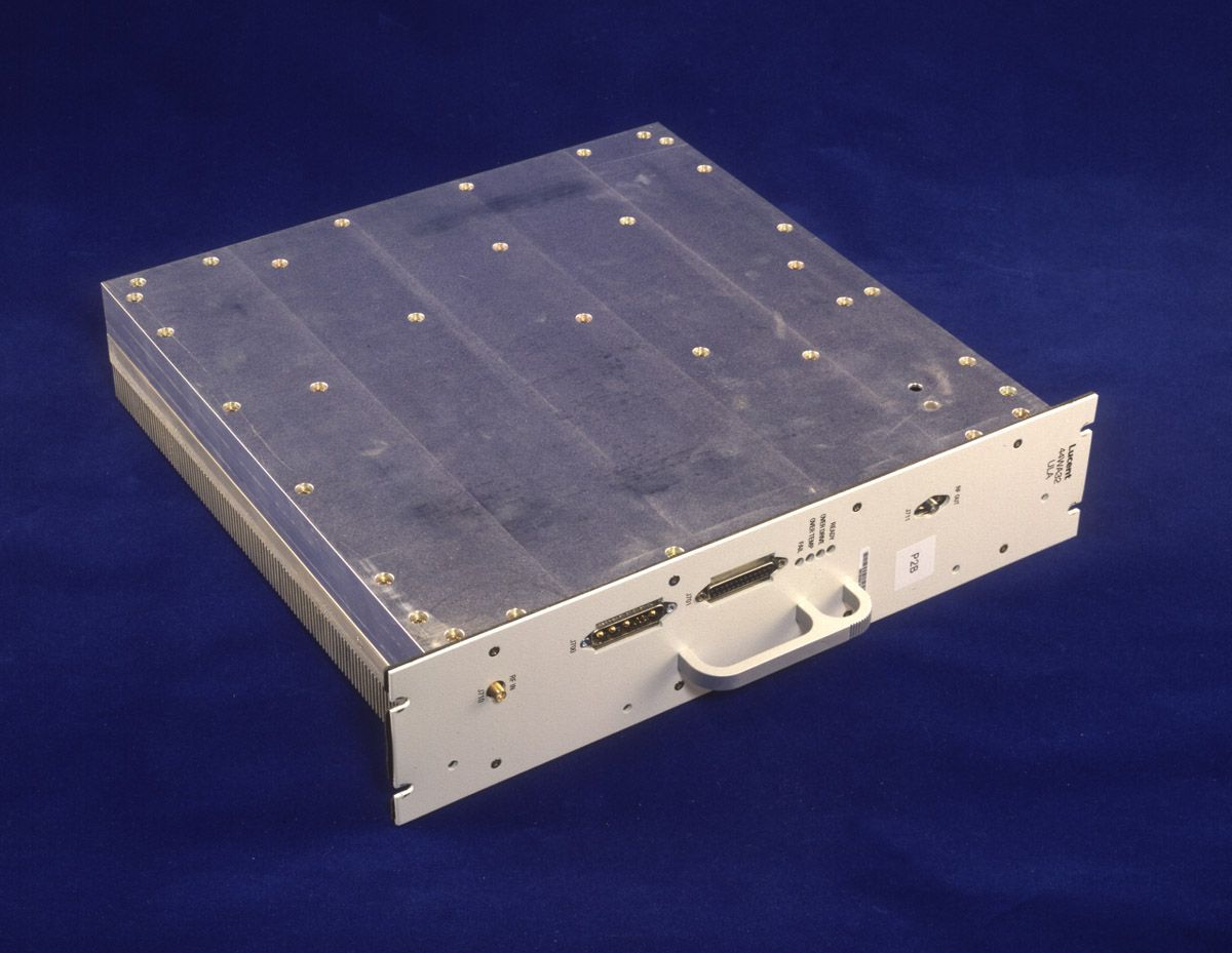
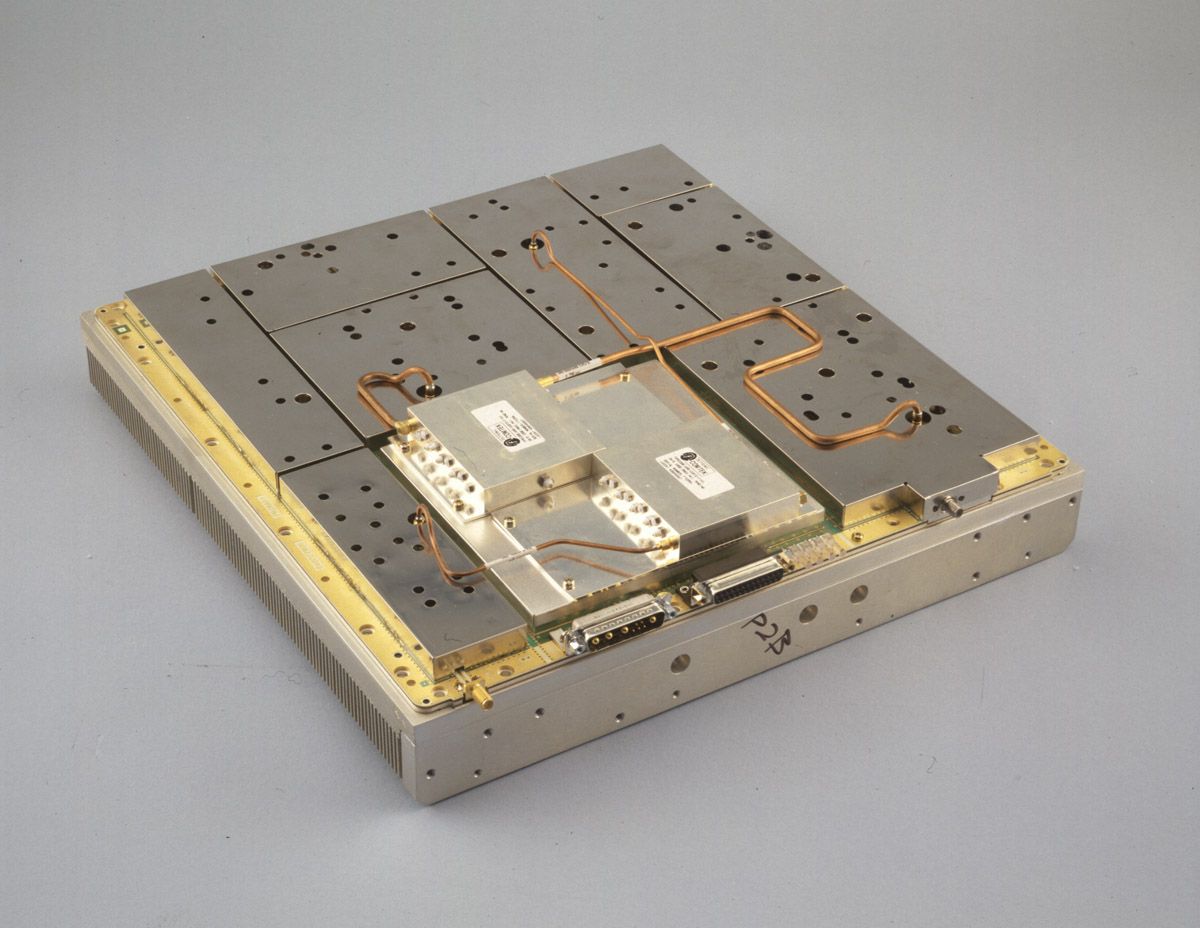
AS5CMP-36Ultra Linear Amplifier Module (ULAM)
Nokia of America Corporation
Click to zoom
Application Details
- Equipment Class
- AMP - Amplifier
- Date of Grant
- Jan 02, 2000
- Application Purpose
- Original Equipment
- Date of Application
- Sep 19, 1999
- Equipment Note
- Ultra Linear Amplifier Module (ULAM)
- Frequency Range
- 1950.00000000 - 1965.00000000
- Company
- Nokia of America Corporation
- Country
- United States
Documents & Files
Document Text
Text extracted from the exhibit documents filed with the FCC. Open a document above to read the original.
Attestation Statements
APPLICANT: Lucent Technologies Inc. -1 - FCC ID: AS5CMP-36 Lucent Technologies Inc. - Proprietary Use pursuant to Company Instructions. 1 Exhibit 1 September 15, 1999 SECTION 2.911 (d) QUALIFICATION OF ENGINEERS Walter Steven Majkowski is a Member of Technical Staff at Lucent Technologies Bell Laboratories. He holds a BSEE from New Jersey Institute of Technology and was trained in the FCC testing procedures. Mr. Majkowski is a NARTE certified EMC engineer, Certificate number EMC- 001859-NE, and has at least twenty years of EMC design and testing experience. R.J. Pillmeier Member Technical Staff Cell Test and Field Support APPLICANT: Lucent Technologies Inc. -2 - FCC ID: AS5CMP-36 Lucent Technologies Inc. - Proprietary Use pursuant to Company Instructions. 2 Exhibit 1 continued SECTION 2.911 (d) CERTIFICATION OF TECHNICAL TEST DATA I hereby certify that the technical test data are the results of tests performed or supervised by me. Walter Steven Majkowski NCE Member Technical Staff Whippany Compliance Laboratory
Attestation Statements
APPLICANT: Lucent Technologies Inc. -18 - FCC ID: AS5CMP-36 Lucent Technologies Inc. - Proprietary Use pursuant to Company Instructions. 18 Exhibit 2 SECTION 2.1033(a) Name of applicant indicating whether the applicant is the manufacturer of the equipment, a vendor other than the manufacturer (include the name of the manufacturer), a licensee or a prospective licensee. RESPONSE: APPLICANT:Lucent Technologies 600 Mountain Avenue Murray Hill, NJ 07974 Attention: Mrs. J. Zakutansky Lucent Technologies, Inc. will be the manufacturer of this product. The AS5CMP-36 will only be marketed under the Lucent Technologies Inc. trademark. SECTION 2.1033(b) Identification of equipment for which Product Certification is sought. RESPONSE: PCS Land Station Ultra Linear Amplifier Module/ Multi Carrier Amplifier (ULAM / MCA) to be operated under Part 24 (E) of the FCC Rules as FCC ID: AS5CMP-36. SECTION 2.1033(c) Information whether quantity (more than one) production is planned. RESPONSE: A large quantity of production is anticipated.
Attestation Statements
APPLICANT: Lucent Technologies Inc. -58 - FCC ID: AS5CMP-36 Lucent Technologies Inc. - Proprietary Use pursuant to Company Instructions. 58 Exhibit 20 Human Exposure Compliance Statement After evaluation of this equipment by the Lucent Technologies Bell Laboratories "Radiation Protection Services" staff, Lucent Technologies, Inc. certifies that it complies with IEEE C95.1- 1991, "IEEE Standards for Safety Levels with Respect to Human Exposure to Radio Frequency Electronic Fields, 3 kHz to 300s GHz" as measured using methods specified in IEEE C95.3-1991, "Recommended Practice for the Measurement of Potentially Hazardous Electromagnetic Fields - RF and Microwave." In recognition of the variation of characteristics from site to site, this certification is based on the measurement of any particular site which has been installed in compliance with the instructions supplies with this the equipment.
Cover Letter(s)
APPLICANT: Lucent Technologies Inc. -1 - FCC ID: AS5CMP-36 Lucent Technologies Inc. - Proprietary Use pursuant to Company Instructions. 1 Federal Communications Commission Office of Engineering and Technology Equipment Authorization Division, Application Processing Branch Lucent Technologies Inc. 67 Whippany Road Whippany, NJ 07981 September 15, 1999 Federal Communications Commission Office of Engineering and Technology Authorization and Evaluation Division Equipment Authorization Branch 7435 Oakland Mills Road Columbia, Maryland 21046 Dear Examiner: In accordance with Parts 2 and 24 of the Commission’s Rules and Regulations, we are submitting herewith, statements and supporting data to show compliance with the requirements of the Commission for Product Certification of the Lucent Technologies Corp. Ultra Linear Amplifier Module/ Multi Carrier Amplifier, henceforth ULAM, FCC ID: AS5CMP-36. This ULAM is used in Lucent Technologies Corp FLEXENT Land Station Cellular system using Code Division Multiple Access (CDMA) technology, for use in Domestic Personal Communication Services. This application for the ULAM, under FCC ID: AS5CMP-36, is for operation in PCS Blocks A and B. The ULAM is capable of operation in all PCS Blocks but production filters are only available at the time of filing for the tested Blocks. The ULAM is a nominally 32 Watt Class A CW amplifier designed to provide 16 watts of long term average at the antenna connection port. During actual operation under the dynamic conditions of CDMA service this amplifier will provide 24 watts at the antenna connection port (J4) and this is the value used for this filing. The ULAM is configurable in a single, dual or three amplifier “Multi Carrier Amplifier” (MCA) with external passive signal combiners and splitters. The ULAM/ MCA provides up to 24 watts per carrier in each of the MCA configurations (single, dual or three amplifier) with a total J4 RF Power of 24, 48 or 72 watts for each of the respective configurations. Under the dynamic conditions of CDMA service a maximum of 24 watts per carrier/ 72 Watts total will be available at the antenna port (J4) of the three ULAM / MCA and this is the value to be used for this filing. APPLICANT: Lucent Technologies Inc. -2 - FCC ID: AS5CMP-36 Lucent Technologies Inc. - Proprietary Use pursuant to Company Instructions. 2 The data summarized below is in the form presently used by the Commission’s Radio Equipment List. ManufacturerLucent Technologies, Inc. Equipment Identification AS5CMP-36 Rules Part Number24 (E) Frequency Range1930–1945 MHz and 1950-1965 MHz: PCS Blocks A and B Output Power0.16 to 24.0 Watts/carrier–up to 72 watts total (3 carrier): Varied By Software Frequency Tolerance+/- 0.5 ppm Emission Designator1M25G9W The unit is called the PCS Ultra Linear Amplifier Module/ Multi Carrier Amplifier. It is designed to the limitations specified in Part 24 subpart E. Whenever possible, the test procedures defined in CFR 47 Parts 2 and 24(E) were followed. Because of the “state of the art” nature of this equipment, some of the characteristics cannot be tested using the requirements in CFR 47. For those characteristics ANSI J-STD-008 were used to define the tests and evaluation criteria used in this application. The ULAM, at its output, is typically operated over the power range of 0.32 to 48.0 watts/carrier. Losses internal to the Modular Cell cabinet, software control, and the passive components of the Multi Carrier Amplifier configuration will limit the output power to 24.0 watts/ carrier when measured at the (J4) antenna connector. The total power is limited to the latter value and is the level for this application. The actual power levels delivered by the ULAM/ MCA are under the software control of the Mobile Switching Center of the local PCS system. The software control only allows for adjustment in power up to the 24.0 Watt maximum. This filing to operate the ULAM/ AS5CMP-36 is based upon signals supplied to the ULAM by a Lucent Technologies Inc. CDMA Baseband Radio 1900 (CBR-1900 henceforth CBR), FCC ID: AS5CMP-26, granted 23 March 1999 for all PCS Blocks. This application for AS5CMP-36, is for PCS Blocks "A" and "B". The amplifier is capable of operation in all PCS Blocks but production transmit filters for other PCS Blocks are not yet available. Since this application encompasses the single, dual and three carrier configurations it presents the required test data for each of those ULAM/ MCA operational configurations. The ULAM/ AS5CMP-36 is produced by Lucent Technologies Inc. solely for incorporation into Lucent Technologies Inc. products. The CBR/ AS5CMP-26 is a Lucent Technologies Inc. designed and manufactured products. Enclosed in this electronically transmitted online package is a copy of FCC Form 731 (Application for Equipment Authorization - Radio Frequency Devices) and the required exhibits. These exhibits contain the technical data, and the required statements and documents for Product Certification. The APPLICANT: Lucent Technologies Inc. -3 - FCC ID: AS5CMP-36 Lucent Technologies Inc. - Proprietary Use pursuant to Company Instructions. 3 technical contact at Lucent Technologies, Bell Laboratories, will comply with any request for additional information should the need arise. Sincerely, R.J.Pillmeier Member Technical Staff Cell Test and Field Support Phone: 973-386-3837 email: [email protected] Att FCC Form 731 w/ Attachments Technical Contact W. Steve Majkowski Phone 973-386-3812 email: [email protected] Adminstrative Contact/ FCC Coordinator Jane Zakutansky Compliance Manager Phone 908- 582-5029 Email: [email protected] APPLICANT: Lucent Technologies Inc. -4 - FCC ID: AS5CMP-36 Lucent Technologies Inc. - Proprietary Use pursuant to Company Instructions. 4 TABLE OF CONTENTS Exhibit 1Section 2.911 (d)Qualifications and Certifications Exhibit 2Section 2.1033(a) (b) (c)Manufactures, Identification, Production Exhibit 3Section 2.1033(c) (1-5)Emission, Freq. Ran…
Text truncated - open the document above for the full version.
Cover Letter(s)
APPLICANT: Lucent Technologies Inc. -1 - FCC ID: AS5CMP-36 Lucent Technologies Inc. - Proprietary Use pursuant to Company Instructions. 1 Federal Communications Commission Office of Engineering and Technology Authorization and Evaluation Division Equipment Authorization Branch 7435 Oakland Mills Road Columbia, Maryland 21046 Re: Request for Confidentiality for FCC ID: AS5CMP-36 Dear Examiner: On behalf of the Lucent Technologies Network Wireless System Business Unit, I hereby request that the following exhibits included in the Product Certification application for FCC ID: AS5CMP-36 be maintained as confidential information and not be made available for public inspection at any time. 1. Exhibit 4Section 2.1033(c) (8) Active Circuit Devices Drive Levels 2. Exhibit 5Section 2.1033(c) (10) Complete Circuit Diagrams 3. Exhibit 6Section 2.1033(c) (3) Instruction Book 4. Exhibit 7Section 2.1033(c) (9) Tune-Up procedure 5. Exhibit 8Section 2.1033(c) (10) Circuitry for determining frequency 6. Exhibit 9Section 2.1033(c) (11) Circuitry for Suppression of Spurious These exhibits contain Lucent Technologies proprietary information considered to be trade secrets and the property of Lucent Technologies, pursuant to the provisions of Section 0.457(d) of the Commission’s Rules. Thank you for your consideration in this matter. Sincerely, R.J.Pillmeier Member Technical Staff Cell Test and Field Support
Cover Letter(s)
APPLICANT: Lucent Technologies Inc. -1 - FCC ID: AS5CMP-36 Lucent Technologies Inc. - Proprietary Use pursuant to Company Instructions. 1 Federal Communications Commission Office of Engineering and Technology Equipment Authorization Division, Application Processing Branch Lucent Technologies Inc. 67 Whippany Road Whippany, NJ 07981 September 22, 1999 Federal Communications Commission Office of Engineering and Technology Authorization and Evaluation Division Equipment Authorization Branch 7435 Oakland Mills Road Columbia, Maryland 21046 Subject FCC ID: AS5CMP-36731 Confirmation # EA95441 Dear Ms.and Sir It is requested on the above referenced application that all information regarding Exhibit 14 be held as confidentional. The proper "Check" box may not have been activated during the upload proceedure. Thank You, Sincerely, Walter S Majkowski NCE Whippany Compliance Laboratory Lucent Technologies Inc. 973 386 3812 [email protected] R.J.Pillmeier Member Technical Staff Cell Test and Field Support Phone: 973-386-3837 email: [email protected] Adminstrative Contact/ FCC Coordinator Jane Zakutansky Compliance Manager Phone 908- 582-5029 Email: [email protected]
ID Label/Location Info
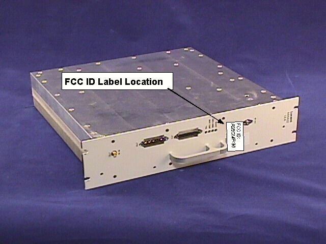
APPLICANT: Lucent Technologies Inc. -1 - FCC ID: AS5CMP-36 Lucent Technologies Inc. - Proprietary Use pursuant to Company Instructions. 1 Exhibit 18 SECTION 2.1033(f) A photograph or drawing of the equipment identification plate or label showing the information to be placed thereon. RESPONSE: The equipment identification label information for the ULAM/MCA / FCC ID: AS5CMP-36 is attached. APPLICANT: Lucent Technologies Inc. -2 - FCC ID: AS5CMP-36 Lucent Technologies Inc. - Proprietary Use pursuant to Company Instructions. 2 Exhibit 18 FCC ID Label Drawing for AS5CMP-36
ID Label/Location Info
Applicant: Lucent Technologies FCC ID: AS5CMP-36 Lucent Technologies Inc - Proprietary Use pursuant to Company Instructions Exhibit 18 SECTION 2.1033(f) A photograph or drawing of the equipment identification plate or label showing the information to be placed thereon. RESPONSE: The equipment identification label information for the ULAM/MCA / FCC ID: AS5CMP-36 is attached. Applicant: Lucent Technologies FCC ID: AS5CMP-36 Lucent Technologies Inc - Proprietary Use pursuant to Company Instructions Exhibit 18 FCC ID Label Drawing for AS5CMP-36
Operational Description
APPLICANT: Lucent Technologies Inc. -18 - FCC ID: AS5CMP-36 Lucent Technologies Inc. - Proprietary Use pursuant to Company Instructions. 18 Exhibit 3 SECTION 2.1033(c) Technical description of the equipment sufficiently complete to develop all the factors concerning compliance with the technical standards of the applicable rules part. The description shall include the following items: SECTION 2.1033(c) (1) Type or types of emission. RESPONSE: The AS5CMP-34 is capable of amplifying transmissions involving the following types of emissions: 1M25G9W (CDMA) SECTION 2.1033(c) (2) Frequency Range. RESPONSE:1930–1945 MHz and 1950-1965 MHz : PCS Blocks A and B (This application is for PCS Blocks A and B. ) SECTION 2.1033(c) (3) Range of operating power values or specific operating power levels, and description of any means provided for variation of operating power. RESPONSE: The AS5CMP-36 amplifier is capable of operating from 0.32 to 48.0 Watts CW per carrier at the amplifier output. The output power that is delivered to the J4 antenna output connector of the cabinet in which the AS5CMP-36 is mounted is reduced from this maximum value by filter insertion loss, RF transmission losses and margin for long term reliability. The power is also under continuous software control. When installed in a cabinet with applicable filters the long term average rated power at the J4 antenna output connector is 24 Watts per carrier +2 /-4 dB. The maximum power for three carriers in the Multi Carrier Amplifier configuration is 72 Watts Total +2 /-4 dB. SECTION 2.1033(c) (4) Maximum power rating as defined in the applicable part of the rules. RESPONSE: The maximum average power output of the AS5CMP-36 at the J4 antenna output connector is 24 Watts per carrier +2 /-4 dB. The maximum power for three carriers in the Multi Carrier Amplifier configuration is 72 Watts Total +2 /-4 dB. APPLICANT: Lucent Technologies Inc. -19 - FCC ID: AS5CMP-36 Lucent Technologies Inc. - Proprietary Use pursuant to Company Instructions. 19 Exhibit 3 continued SECTION 2.1033(c) (5) The dc voltages applied to and dc currents into the several elements of the final radio frequency amplifying device for normal operation over the power range. RESPONSE: 2 Transistors combined in each Chain. Total of four devices; each draws about 2.7 amps at 28 volts
Operational Description
APPLICANT: Lucent Technologies Inc. Exhibit 10 -26 - FCC ID: AS5CMP-36 Lucent Technologies Inc. - Proprietary Use pursuant to Company Instructions. 26 Exhibit 10 SECTION 2.1033(c) (12) For equipment employing digital modulation techniques, a detailed description of the modulation system to be use, including response characteristics of any filters provided, and a description of the modulating wavetrain, shall be submitted for the maximum rated conditions under which the equipment will be operated. RESPONSE: These functions are controlled by the CDMA Baseband Radio (CBR), FCC ID: AS5CMP-26. The CBR was “Granted” 23 March 1999 for all PCS Blocks. The CBR / AS5CMP-26 supplies the signals to be amplified. This information was included with the original filing documents for the CBR/ AS5CMP-26. This information is unchanged from that original filing.
Test Report
APPLICANT: Lucent Technologies Inc. Exhibit 12 -1 - FCC ID: AS5CMP-36 Lucent Technologies Inc. - Proprietary Use pursuant to Company Instructions. 1 Exhibit 12 SECTION 2.1046 MEASUREMENT OF RADIO FREQUENCY POWER OUTPUT The test arrangements used to measure the radio frequency power output of the ULAM / AS5CMP-36 Ultra Linear Amplifier Module is on the following page. Measurements were made respectively at each frequency where Occupied Bandwidth measurements were performed. The use of the ULAM requires that the J4 power level be calibrated for each specific channel of use. The test configuration, Figure 12a, allowed the measurement of output power for each channel investigated for Occupied Bandwidth. These included the “Left” and “Right” Edge of Block and at a center channel for each Block. The ULAM system has a maximum power output at the antenna terminals of 24.0 Watts (43.8 dBm) +2 / -4 dB per Carrier or 72 Watts total for a three carrier MCA. It also has a minimum power output at the antenna terminals of 0.16 Watts ( +2 / -4 dB, across the PCS downlink Band (1930.00-1990.00 MHz). The signal applied to the ULAM is defined in Table 12.1. The power was reset to 24.0 Watts/carrier at each measurement frequency to verify the spectral performance at that power level at each specific frequency of interest. The attenuation range was also verified. The specific Frequencies, channels and set power level was documented on each "Occupied Bandwidth" data sheet. These were performed for single dual and three carrier configurations. The applied signal met the recommended characteristics per ANSI J-STD-008 section 3.1.4 as defined below. TypeNumber of Channels Fraction of Power (Linear) Fraction of Power (dB) Comments Pilot 1 0.1490-8.3Walsh 0 Sync 1 0.015/p-18.3 Walsh 32, always 1/8 rate Paging 1 0.054 -12.7 Walsh 1, full rate only Traffic 6 0.13 each -8.8 each Variable Walsh Assignments, full rate only TABLE 12.1 Base Station Test Model, Nominal APPLICANT: Lucent Technologies Inc. Exhibit 12 -1 - FCC ID: AS5CMP-36 Lucent Technologies Inc. - Proprietary Use pursuant to Company Instructions. 1 Exhibit 12 RF Power Test Configuration Figure 12A/14A/15A Test Configuration For RF Power, Occupied Bandwidth and Conducted Spurious Peak Input Level = -10 dBm Rohde & Schwartz ESMI EMI Test Receiver/ Spectrum Analyzer Typically -30 dB from J4 Connection Power Sensor HP-8481A Calibrated to J4 Connection 48.6 dBm Power Meter HP-772D Directional Coupler Incident Reflected PCS Modular Cell ULAM Test Figure WSM 9/16/99 Transmit Filter Reference Frequency Timing Unit (TFU AND OSC) CBR AS5CMP-26 ULAM AS5CMP-36 Output Input 3:1:3 Combiner/ Splitter Output Output CBR AS5CMP-26 CBR AS5CMP-26 ULAM AS5CMP-36 ULAM AS5CMP-36 3:1 Combiner Output Port J4 Lucent FLEXENT PCS CDMA MODULAR CELL 1 SECTOR SHOWN Carrier Reject High Pass Filter For Conducted Spurious Measurements above 2.5 GHz GPIB Test Controller APPLICANT: Lucent Technologies Inc. Exhibit 12 -1 - FCC ID: AS5CMP-36 Lucent Technologies Inc. - Proprietary Use pursuant to Company Instructions. 1 Exhibit 12 Equipment used in Figure 12 For Measurement of RF Power PCS Modular Cell:Fully Populated PCS Modular Cell OM 1&2 :Oscillator Module, 15 MHz Rubidium and Crystal types CBR: 1-9:CDMA Baseband Radio (FCC ID: AS5CMP-26) ULAM: 1-9:Ultra Linear Amplifier Module (FCC ID: AS5CMP-36) Transmit Filter:PCS Block Transmit Filter appropriate for the investigated Block Directional Coupler:HP 778D and 772D Dual Directional Coupler Power Meter:HP E4419A Power Meter with EPC-E18A Power Head Test Cables:W.L. Gore; Low loss test cables custom mfg. for Lucent FCC Laboratory Plotter:HP Model 7470A Plotter Printer:HP Model 4500DN Printer Attenuators, VariableHP 8494B and 8495B DC-18 GHz digital attenuators Attenuators, FixedWeinschel Corp DC-18 GHz, various values Spectrum Analyzer: Rohde & Schwarz ESMI EMI Test Receiver Band Pass Filters:Trialithic, 1-18 GHz, Custom manufactured for Lucent FCC Laboratory Computer Controller:EG Technology, Custom Mfg for FCC Laboratory Intel Pentium II& III, 450 and 550 MHz controllers with TILE software APPLICANT: Lucent Technologies Inc. Exhibit 12 -2 - FCC ID: AS5CMP-36 Lucent Technologies Inc. - Proprietary Use pursuant to Company Instructions. 2 Exhibit 12 RESULTS: The ULAM/ AS5CMP-36 was configured in the test setup shown in Figure 12A. For each of the PCS channels tested the ULAM/ AS5CMP-36 delivered a minimum of 24.0 Watts per carrier +2/-0 dB when measured at the J4 output connection. This data is recorded on the Occupied Bandwidth Data Sheets for “Left edge”, and “Right Edge” channels for each frequency Block / Sub-Block. For PCS Block A, the Sub-Block filter A1 is for the “Left Edge of Block” and is designed for as many as three carriers. Likewise the Sub-Block filter A4 is for the “Right Edge of Block” and will accommodate two carrier. Block B is partitioned identically. When operated in the multi-carrier MCA configuration the A1/ A4 or B1/B4 Occupied Bandwidth plots present three center channel performance charts. Data is presented for PCS Blocks “A”, and “B” . Note: The ULAM/ AS5CMP-36 can be operated as a single carrier or as a Multiple Carrier CDMA amplifier. The maximum power level are verified at each cell site during setup of the PCS CDMA Modular Cell and installation of the CBR, FCC ID: AS5CMP-26.
Test Report
APPLICANT: Lucent Technologies Inc. -32 - FCC ID: AS5CMP-36 Lucent Technologies Inc. - Proprietary Use pursuant to Company Instructions. 32 Exhibit 13 SECTION 2.1047 MEASUREMENT OF MODULATION CHARACTERISTICS The modulation characteristics and accuracy of the ULAM/ AS5CMP-36 output signal is a solely a function of the input signal which is provided by the CBR/ AS5CMP-26, Granted 23 March 1999.
Test Report
APPLICANT: Lucent Technologies Inc. Exhibit 14 -1 - FCC ID: AS5CMP-36 Lucent Technologies Inc. - Proprietary Use pursuant to Company Instructions. 1 Exhibit 14 SECTION 2.1049MEASUREMENT OF OCCUPIED BANDWIDTH Because of the Multi Carrier application of the ULAM, occupied bandwidth measurements were performed for all three of the MCA configurations. This documents the typical performance of the ULAM while supplied with single, dual and three CDMA carriers. Since the ULAM is a fixed gain device all power adjustments were performed via the CBR/ FCC ID: AS5CMP-26. The occupied bandwidth of the ULAM/ FCC ID: AS5CMP-36 was measured using a Rohde & Schwarz ESMI EMI Test Receiver and a HP Model 7470A Plotter. The RF power level was measured and adjusted via the test setup in Figure 14A. The calibrated RF output from the transmitter was reduced (to an amplitude usable by the spectrum analyzer) by using a calibrated attenuator. This attenuation was offset on the display and the signal adjusted to the -16.2 dBc level corresponding to the corrected RF power level for a 30 kHz resolution bandwidth. The power calibration was individually verified at each carrier for a 1.25 MHz resolution bandwidth. This value corresponds to the top of the Occupied Bandwidth mask. The top of the mask accurately corresponds to the specified power of 24 watts per carrier / 43.8 dBm. All of the plots are presented with a 7.5 MHz span and the center frequency of the specific Sub-Block of interest. This allows for ease of comparison of the single, dual and three carrier performance. This data is recorded on the Occupied Bandwidth Data Sheets for “Left edge”, and “Right Edge” channels for each frequency Block / Sub-Block. For PCS Block A, the Sub-Block filter A1 is for the “Left Edge of Block” and is designed for as many as three carriers. Likewise the Sub-Block filter A4 is for the “Right Edge of Block” and will accommodate a maximum of two carrier. Block B is partitioned identically. Sub-Block Filters for A2, A3, B2, B3 When operated in the multi-carrier MCA configuration the A1 and B1 Occupied Bandwidth plots present one, two and three center channel performance charts at the respective Left Edge of Block. The A4 and B4 Plots present one and two carrier performance at the Right Edge of their respective Blocks. The frequencies and channels used are tabulated on the bottom of each plot. Input and output signals are plotted at each frequency/ channel. Plots are provided for Left Edge, Center and Right Edge of each PCS Block evaluated. These frequencies were chosen to show the occupied bandwidth in the channels in each of the PCS Blocks in which this radio can be operated, in compliance with Section 24.229 and 24.238 (c) of the Commission code. There are no SAT or Wide band data signals associated with CDMA. The signal used to show the occupied bandwidth is defined in table 14.1. This is the signal recommended in ANSI-J-STD-008 Section 3.1.4. The power output level was adjusted to provide the documented power levels at the bottom of each chart. APPLICANT: Lucent Technologies Inc. Exhibit 14 -2 - FCC ID: AS5CMP-36 Lucent Technologies Inc. - Proprietary Use pursuant to Company Instructions. 2 The applied signal met the recommended characteristics per ANSI J-STD-008 section 3.1.4 as defined below. TypeNumber of Channels Fraction of Power (Linear) Fraction of Power (dB) Comments Pilot 1 0.1490-8.3Walsh 0 Sync 1 0.015/p-18.3 Walsh 32, always 1/8 rate Paging 1 0.054 -12.7 Walsh 1, full rate only Traffic 6 0.13 each -8.8 each Variable Walsh Assignments, full rate only TABLE 14.1 Base Station Test Model, Nominal Exhibit 14 continued The minimum standard presented in ANSI-J-STD-008 Section 4.5.1.3.1 was followed. “Suppression Inside the Licensee’s Frequency Block(s)” For all frequencies within the base station transmit band of 1930.000 to 1990.000 MHz that are within the specific block(s) allocated to the operator's system, the total conducted spurious emissions in any 30kHz band greater than 885 kHz for the CDMA channel center frequency shall not exceed a level of -45 dBc.... Measurement at a Resolution Bandwidth of 30 kHz is based on our experience with Section 24.238 of The Code and lacking other guidance. The spectrum analysis output plots shows the peak of the CDMA channel signal 16.19 dB below the Mask reference / “zero dBc line” of the spectrum analyzer for the following reason: For the CDMA system there is no carrier without modulation. The following relationship was used to provide the correct level for an unmodulated carrier vs. the modulated signal. 10*log (Resolution Bandwidth/ Transmit Bandwidth) = Signal Offset (1) For the peak of the CDMA signal measured with a resolution bandwidth of 30 kHz the signal offset is: Signal Offset = 10*log (30 kHz /1.25 MHz ) = -16.19 dB APPLICANT: Lucent Technologies Inc. Exhibit 14 -3 - FCC ID: AS5CMP-36 Lucent Technologies Inc. - Proprietary Use pursuant to Company Instructions. 3 Exhibit 14 continued Measurement All of the tolerance lines for the output are referenced to the top of the Occupied Bandwidth mask, which is defined as 43.8 dBm/ zero dBc. For all measurements of the ULAM / MCA's Occupied Bandwidth, the output power was measured / adjusted individually to the 24 W level for each carrier and this is the 43.8 dBm value at the 0 dBc reference line. In order to depict the tolerance lines that are required by Sec 24.238 of the FCC Rules and ANSI J-STD- 008, all measurements were made with a resolution bandwidth of 30 kHz and the limits were adjusted using equation (1). An average detector was employed using minimum of 25 sweeps per trace. Mask Description for Single Carrier The Mask limits are identical for the left and right side of the PCS Blocks and are as follows. Figure 14-B shows the Mask limit for PCS channel 25 which is the left block edge for Block A and the band edge for the PCS band. The Spectrum Analyzer reference level is set above the Signal Reference to allow for the …
Text truncated - open the document above for the full version.
Test Report
APPLICANT: Lucent Technologies Inc. Exhibit 14 -1 - FCC ID: AS5CMP-36 Lucent Technologies Inc. - Proprietary Use pursuant to Company Instructions. 1 Exhibit 14 Continued Figure 14A Figure 12A/14A/15A Test Configuration For RF Power, Occupied Bandwidth and Conducted Spurious Peak Input Level = -10 dBm Rohde & Schwartz ESMI EMI Test Receiver/ Spectrum Analyzer Typically -30 dB from J4 Connection Power Sensor HP-8481A Calibrated to J4 Connection 48.6 dBm Power Meter HP-772D Directional Coupler Incident Reflected PCS Modular Cell ULAM Test Figure WSM 9/16/99 Transmit Filter Reference Frequency Timing Unit (TFU AND OSC) CBR AS5CMP-26 ULAM AS5CMP-36 Output Input 3:1:3 Combiner/ Splitter Output Output CBR AS5CMP-26 CBR AS5CMP-26 ULAM AS5CMP-36 ULAM AS5CMP-36 3:1 Combiner Output Port J4 Lucent FLEXENT PCS CDMA MODULAR CELL 1 SECTOR SHOWN Carrier Reject High Pass Filter For Conducted Spurious Measurements above 2.5 GHz GPIB Test Controller APPLICANT: Lucent Technologies Inc. Exhibit 14 -2 - FCC ID: AS5CMP-36 Lucent Technologies Inc. - Proprietary Use pursuant to Company Instructions. 2 Exhibit 14 continued Figure 14B Occupied Bandwidth Mask aa b a c d e f g tth Fc 43.8 dBm / 0 dBc 27.6 dBm/ -16.2 dBc
Test Report
Applicant: Lucent Technologies FCC ID: AS5CMP-36 Lucent Technologies Inc - Proprietary Use pursuant to Company Instructions FCC Occupied Bandwidth Data Scans of Lucent Technologies Inc. PCS Ultra Linear Amplifier Module /Multi Carrier Amplifier (ULAM/ MCA) Block A Data Single, Dual and Three Carrier MCA Configurations Applicant: Lucent Technologies FCC ID: AS5CMP-36 Lucent Technologies Inc - Proprietary Use pursuant to Company Instructions FCC Occupied Bandwidth: Input Chart - PCS A Block, Sub-Block A1, Single Carrier Configuration ULAM/MCA Applicant: Lucent Technologies FCC ID: AS5CMP-36 Lucent Technologies Inc - Proprietary Use pursuant to Company Instructions FCC Occupied Bandwidth: Output Chart - PCS A Block, Sub-Block A1, Single Carrier Configuration ULAM/MCA Applicant: Lucent Technologies FCC ID: AS5CMP-36 Lucent Technologies Inc - Proprietary Use pursuant to Company Instructions FCC Occupied Bandwidth: Input Chart - PCS A Block, Sub-Block A1, Dual Carrier Configuration ULAM/MCA Applicant: Lucent Technologies FCC ID: AS5CMP-36 Lucent Technologies Inc - Proprietary Use pursuant to Company Instructions FCC Occupied Bandwidth: Output Chart - PCS A Block, Su…
Text truncated - open the document above for the full version.
Contact Information
Applicant
Raymond J. Johnson(Technical Manager)
Technical Contact
Lucent Technologies Inc. / Whippany FCC LabWalter S Majkowski
[email protected]973-386-3812
Room 1C-224C · Whippany, New Jersey · United States
Non-Technical Contact
Lucent Technologies Inc. / Whippany FCC LabRudolph J Pillmeier
[email protected]973 386 3837
Technical Specifications
| # | Rule Parts | Frequency Range | Power Output | Emission | Tolerance |
|---|---|---|---|---|---|
| 2 | 24E | 1.95 GHz - 1.97 GHz | 24 W | F9W | Amp |
Other Applications from Nokia of America Corporation

AS5BBTRX-23
Mar 15, 2015B13 RRH 4X30
Equipment Class
TNB - Licensed Non-Broadcast Station Transmitter
AS5BBTRX-21
Feb 01, 2015PCS LTE 9764 Metro Cell Outdoor Transceiver System
Equipment Class
PCB - PCS Licensed Transmitter
AS5BBTRX-22
Jan 26, 2015B25 RRH 4X30
Equipment Class
PCB - PCS Licensed Transmitter
AS5BBTRX-17
Jan 08, 2014AWS LTE 9764 Metro Cell Outdoor Transceiver System
Equipment Class
TNB - Licensed Non-Broadcast Station Transmitter
AS5BBTRX-14
Dec 18, 20139763 MCI B25 PCS LTE 2x250mW
Equipment Class
PCB - PCS Licensed Transmitter