AS5LTIMDW9GFrequency Hopping Transmitter
Nokia of America Corporation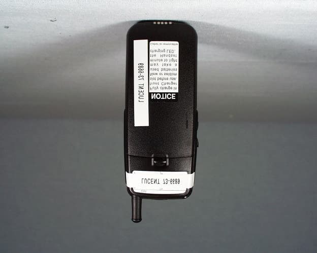
Click to zoom
Application Details
- Equipment Class
- DSS - Part 15 Spread Spectrum Transmitter
- Date of Grant
- Jan 28, 1999
- Application Purpose
- Original Equipment
- Date of Application
- Nov 29, 1998
- Equipment Note
- Frequency Hopping Transmitter
- Frequency Range
- 902.10000000 - 927.90000000
- Company
- Nokia of America Corporation
- Country
- United States
Documents & Files
Document Text
Text extracted from the exhibit documents filed with the FCC. Open a document above to read the original.
Users Manual
Lucent Technologies Bell Labs Innovations TransTalk™ 9000 Digital Wireless System MDW 9031 Wireless Pocketphone Installation and Use 503-801-166 Comcode 108170176 Issue 1 November 1997 Copyright ©1997 Lucent Technologies All Rights Reserved Printed in U.S.A. Lucent Technologies 503-801-166 Comcode 108170176 Issue 1 N ovember 1997 Notice Every effort was made to ensure that the information in this book was complete and accurate at the time of printing. However, information is subject to change. The pictures in this book are for illustrative purposes only; your actual hardware may look slightly different. Federal Communications Commission (FCC) and Industry Canada (IC) Information For details, see Appendix B. Security Toll fraud, the unauthorized use of your telecommunications system by an unauthorized party (for example, persons other than your company’s employees, agents, subcontrac- tors, or persons working on your company’s behalf) can result in substantial additional charges for your telecommunications services. You are responsible for the security of your system. There may be a risk of toll fraud associated with your telecommunications system. You are responsible for programming and configuring your equipment to prevent unautho- rized use. Your system administrator should read all documents provided with this product to fully understand the features that can introduce the risk of toll fraud and the steps that can be taken to reduce that risk. Lucent Technologies does not warrant that this product is immune from or will prevent unauthorized use of common-carrier telecommunication services or facilities accessed through or connected to it. Lucent Technologies will not be responsible for any charges that result from such unauthorized use. Trademarks TransTalk is a trademark of Lucent Technologies and DEFINITY, MERLIN, MERLIN LEG- END, PARTNER, and SYSTIMAX are registered trademarks of Lucent Technologies. Supra is a registered trademark of Plantronics, Inc. Warranty Lucent Technologies provides a limited warranty for this product; see Appendix A. Ordering Information The order number for this book is 503-801-166. The order number for the MDW 9031 Wireless Pocketphone Quick Reference is 503-801-165. To order additional copies of these reference materials, call 1 800 457-1235 or 1 317 361-5353. To order parts and accessories, see "Ordering Replacement & Optional Parts" in Chapter 4. Customer Support In the continental U.S., call 1 800 628-2888 if you need assistance when using your wireless phone with a PARTNER, MERLIN, or MERLIN LEGEND system. Consultation charges may apply. For all other systems, follow the procedure you normally use to get support for your communications system. Outside the continental U.S., contact your Lucent Technologies Representative or local Authorized Dealer. Contents 1 Introduction 1-1 About TransTalk™ 9000 Products 1-1 What Is a Wireless Phone? 1-1 TransTalk 9000 System 1-1 About the MDW 9031 Pocketphone 1-3 Privacy Information 1-3 Where Can You Use Your Pocketphone? 1-3 Parts List 1-4 Additional Parts 1-5 Spare Battery and Headset 1-6 2 Installing the MDW 9031 Pocketphone Important Safety Instructions Guidelines for Safe and Efficient Operation Exposure to Radio Frequency Energy Cardiac Pacemakers Hearing Aid Compatibility Basic Safety Precautions for Installation and Use Additional Safety Instructions for Installation Personnel AC Outlet Check Installation Overview for Radio Modules and Carriers Radio Module/Switch Wiring Key Components Positioning a Radio Module or Carrier(s) General Positioning Rules Installing a Single Radio Module Single Radio Module Installation Self Test Understanding Carriers Understanding Your Model 117A3 Carrier Setting the 117A3 Carrier Power Level Setting the 117A3 Carrier Control/Expansion DIP Switch 2-1 2-1 2-2 2-2 2-2 2-2 2-3 2-4 2-5 2-6 2-6 2-7 2-9 2-9 2-11 2-12 2-13 2-13 2-15 2-16 i Understanding Your Model 117A4 Carrier Installing a Single Carrier Installing a Single Carrier on a Shelf or Desk Installing a Single Carrier on a Wall Single Carrier Installation Self Test Installing Multiple Carriers Mounting and Cabling Multiple Carriers Multiple Carrier Mounting and Cabling Self Test Installing a Single Radio Module in Each Carrier Installation Self Test with a Single Radio Module in Each Carrier Installing the Remaining Radio Modules Installation Self Test for Remaining Radio Modules 2-18 2-21 2-22 2-25 2-28 2-29 2-29 2-32 2-33 Handset Inserting and Removing the Handset’s Battery Pack Changing the Communications System Setting Filling Out the Handset Label 2-35 2-37 2-39 2-41 2-41 2-42 2-43 Battery Charger Positioning the Battery Charger Installing the Battery Charger Inserting a Battery Pack into the Spare Battery Compartment Removing a Battery Pack from the Spare Battery Compartment Inserting the Handset into the Battery Charger’s Handset Cradle Removing the Handset from the Handset Cradle 2-44 2-44 2-44 2-46 2-47 2-48 2-48 Using the MDW 9031 Pocketphone 3 3-1 Important Safety Instructions3-1 The Handset Handset Controls Column and Select Buttons Handset Display (with Backlighting) Display Messages 3-1 3-2 3-3 3-4 3-5 3-5 3-6 3-6 3-7 Line Status Indicators Range Indicators Low Battery Indicator Volume Control ii Carrying Your Pocketphone Antenna Changing the Handset Settings Changing the Communications System Button Mapping Setting Enabling or Disabling the Vibrator Enabling or Disabling Line Preselection Enabling or Disabling Backlighting Enabling or Disabling the Alerter Test Modes Using Local Test Mode Using Wireless Test Mode "Waking Up" the Phone Making a Call Answering a Call Manually Selecting a Line or Programmed Button Preselecting a Line Using a Headset Using the Headset On/Off Button Answering Calls with a Headset Placing Calls with a Headset The Battery Charger Battery Charger Features Extending Battery Life 3-7 3-8 3-8 3-8 3-9 3-9 3-10 3-11 3-12 3-12 3-13 3-17 3-17 3-17 3-18 3-18 3-19 3-19 3-19 3-20 3-21 3-21 3…
Text truncated - open the document above for the full version.
Cover Letter(s)
COMMUNICATION CERTIFICATION LABORATORYTEST REPORT: 73-6689 FCC ID: AS5LTIMDW9G Page 107 of 108 Exhibit 13 Exhibit 13: Cover Letters November 30, 1998 FEDERAL COMMUNICATIONS COMMISSION Equipment Authorization Division 7435 Oakland Mills Road Columbia, MD 21046 To Whom It May Concern: Enclosed is a FCC Part 15, Subpart C, Section 15.231 Certification application for the Lucent Technologies, Inc. Model MDW9031DCP, FCC ID: AS5LTIMDW9G Please let me know if I can be of further assistance. Sincerely yours, COMMUNICATION CERTIFICATION LABORATORY Joseph W. Jackson V.P. Marketing COMMUNICATION CERTIFICATION LABORATORYTEST REPORT: 73-6689 FCC ID: AS5LTIMDW9G Page 108 of 108 Exhibit 13 Request for Confidentiality Letter
External Photos
COMMUNICATION CERTIFICATION LABORATORYTEST REPORT: 73-6689 FCC ID: AS5LTIMDW9G Page 6 of 108 Exhibit 3 Exhibit 3: Photographs of Overall Appearance Front View of the MDW9031DCP base. COMMUNICATION CERTIFICATION LABORATORYTEST REPORT: 73-6689 FCC ID: AS5LTIMDW9G Page 7 of 108 Exhibit 3 Back View of the MDW9031DCP base. COMMUNICATION CERTIFICATION LABORATORYTEST REPORT: 73-6689 FCC ID: AS5LTIMDW9G Page 8 of 108 Exhibit 3 Front View of the MDW9031DCP handset. COMMUNICATION CERTIFICATION LABORATORYTEST REPORT: 73-6689 FCC ID: AS5LTIMDW9G Page 9 of 108 Exhibit 3 Back View of the MDW9031DCP handset.
ID Label/Location Info
COMMUNICATION CERTIFICATION LABORATORYTEST REPORT: 73-6689 FCC ID: AS5LTIMDW9G Page 1 of 108 Exhibit 1 Exhibit 1: FCC ID Label Equipment Identification Label In accordance with the requirements of Sections 15.19 (a), 2.925 and 2.926 of the FCC Rules, the following information will be permanently affixed to the Lucent Technologies, Inc. Model MDW9031DCP as shown in the photograph below. The FCC ID number is located on both the base and the handset, but due to the size of the handset the compliance statement is located only on the base. Photograph of the back exterior of the base, showing the label placement. COMMUNICATION CERTIFICATION LABORATORYTEST REPORT: 73-6689 FCC ID: AS5LTIMDW9G Page 2 of 108 Exhibit 1 Photograph of the label on the back exterior of the base. COMMUNICATION CERTIFICATION LABORATORYTEST REPORT: 73-6689 FCC ID: AS5LTIMDW9G Page 3 of 108 Exhibit 1 Photograph of the back exterior of the handset, showing the label placement. COMMUNICATION CERTIFICATION LABORATORYTEST REPORT: 73-6689 FCC ID: AS5LTIMDW9G Page 4 of 108 Exhibit 1 Photograph of the label on the back exterior of the handset.
Internal Photos
COMMUNICATION CERTIFICATION LABORATORYTEST REPORT: 73-6689 FCC ID: AS5LTIMDW9G Page 91 of 108 Exhibit 9 Exhibit 9: Internal Photographs Inside View (Base) COMMUNICATION CERTIFICATION LABORATORYTEST REPORT: 73-6689 FCC ID: AS5LTIMDW9G Page 92 of 108 Exhibit 9 Component Side of PCB with RF cans installed (Base) COMMUNICATION CERTIFICATION LABORATORYTEST REPORT: 73-6689 FCC ID: AS5LTIMDW9G Page 93 of 108 Exhibit 9 Opposite Side of PCB with RF cans removed (Base) COMMUNICATION CERTIFICATION LABORATORYTEST REPORT: 73-6689 FCC ID: AS5LTIMDW9G Page 94 of 108 Exhibit 9 Opposite Side of PCB (Base) COMMUNICATION CERTIFICATION LABORATORYTEST REPORT: 73-6689 FCC ID: AS5LTIMDW9G Page 95 of 108 Exhibit 9 Component Side of PCB (Handset) COMMUNICATION CERTIFICATION LABORATORYTEST REPORT: 73-6689 FCC ID: AS5LTIMDW9G Page 96 of 108 Exhibit 9 Opposite Side of PCB (Handset)
Test Report
COMMUNICATION CERTIFICATION LABORATORYTEST REPORT: 73-6689 FCC ID: AS5LTIMDW9G Page 32 of 108 Exhibit 6 Exhibit 6: Test Report TEST REPORT FROM: COMMUNICATION CERTIFICATION LABORATORY 1940 W. Alexander Street Salt Lake City, Utah 84119-2039 Type of Report: Certification TEST OF: MDW9031DCP FCC ID: AS5LTIMDW9G To FCC PART 15.247, Subpart C Test Report Serial No: 73-6689 Applicant: Lucent Technologies, Inc. 600 Mountain Avenue Murray Hill, NJ 07974 Date(s) of Test: November 23 - 25, 1998 Issue Date: November 30, 1998 Equipment Receipt Date: November 20, 1998 COMMUNICATION CERTIFICATION LABORATORYTEST REPORT: 73-6689 FCC ID: AS5LTIMDW9G Page 33 of 108 Exhibit 6 CERTIFICATION OF ENGINEERING REPORT This report has been prepared by Communication Certification Laboratory to determine compliance of the device described below with the requirements of FCC PART 15.247, Subpart C. This report may be reproduced in full, partial reproduction may only be made with the written consent of the laboratory. The results in this report apply only to the sample tested. -Applicant:Lucent Technologies, Inc. -Manufacturer:Lucent Technologies, Inc. -Brand Name:Trans Talk -Model Number:MDW9031DCP -FCC ID:AS5LTIMDW9G On this 30 th day of November 1998, I, individually, and for Communication Certification Laboratory, certify that the statements made in this engineering report are true, complete, and correct to the best of my knowledge, and are made in good faith. COMMUNICATION CERTIFICATION LABORATORY Checked by: William S. Hurst, P.E. Vice President Tested by: Roger J. Midgley EMC Engineering Manager COMMUNICATION CERTIFICATION LABORATORYTEST REPORT: 73-6689 FCC ID: AS5LTIMDW9G Page 34 of 108 Exhibit 6 SECTION 1. CLIENT INFORMATION AND RESPONSIBLE PARTY: 1.1 Client Information: Company Name: Lucent Technologies, Inc. 600 Mountain Avenue Murray Hill, NJ 07974 Contact Name:Irwin Buck Title:Member – Technical Staff COMMUNICATION CERTIFICATION LABORATORYTEST REPORT: 73-6689 FCC ID: AS5LTIMDW9G Page 35 of 108 Exhibit 6 SECTION 2. EQUIPMENT UNDER TEST (EUT) 2.1 Identification of EUT: Trade Name:Trans Talk Model Name or Number:MDW9031DCP Serial Number:108401563 (Base Station) 983300003 (Handset) Options Fitted:None Country of Manufacture:U.S.A. 2.2 Description of EUT: See theory of operation (Exhibit 12). This report covers the transmitter only the receiver is covered under a separate verification report. 2.3 Modification Incorporated/Special Accessories on EUT: There were no modifications or special accessories required to comply with the specification. 2.4 EUT and Support Equipment: The FCC ID numbers for all the EUT and support equipment used during the test (including inserted cards) are listed below: Brand Name Model Number Serial No. FCC ID Number DescriptionName of Interface Ports/Interface Cables BN: Trans Talk MN: MDW9031DCP SN: 108401563 (Base Station) 983300003 (Handset) AS5LTIMDW9GBase Station and Handset (EUT’s) N/A COMMUNICATION CERTIFICATION LABORATORYTEST REPORT: 73-6689 FCC ID: AS5LTIMDW9G Page 36 of 108 Exhibit 6 SECTION 3. TEST SPECIFICATION, METHODS & PROCEDURES 3.1 Test Specification: Title:FCC PART 15.247, Subpart C (47 CFR 15). Limits and methods of measurement of radio interference characteristics of radio frequency devices. Operation within the bands 902-928 MHz, 2400-2483.5 MHz and 5725- 5850 MHz. Purpose of Test: The tests were performed to demonstrate Initial compliance. 3.2 Methods & Procedures: 3.2.1 '' 15.247 (a)Operation under the provisions of this section is limited to frequency hopping and direct sequence spread spectrum intentional radiators that comply with the following provisions: (1)Frequency hoping systems shall have hopping channel carrier frequencies separated by a minimum of 25 kHz or the 20 dB bandwidth of the hopping channel, whichever is greater. The system shall hop to channel frequencies that are selected at the system-hopping rate from a pseudorandomly ordered list of hopping frequencies. Each frequency must be used equally on the average by each transmitter. The system receivers shall have input bandwidths that match the hopping channel bandwidths of their corresponding transmitters and shall shift frequencies in synchronization with the transmitting signals. (i)Frequency hopping systems operating in the 902 - 928 MHz band shall use at least 50 hopping frequencies. The maximum allowed 20 dB bandwidth of the hopping channel is 500 kHz. The average time of occupancy on any frequency shall not be greater than 0.4 seconds within a 20 second period. (ii)Frequency hopping systems operating in the 2400 – 2483.5 MHz and the 5725 – 5850 MHz bands shall use at least 75 hopping frequencies. The maximum allowed 20 dB bandwidth of the hopping channel is 1 MHz. The average time of occupancy on any frequency shall not be greater than 0.4 seconds within a 30 second period. COMMUNICATION CERTIFICATION LABORATORYTEST REPORT: 73-6689 FCC ID: AS5LTIMDW9G Page 37 of 108 Exhibit 6 (2)For direct sequence systems, the minimum 6 dB bandwidth shall be at least 500 kHz. (b)The maximum peak output power of the transmitter shall not exceed 1 watt. If transmitting antennas of directional gain greater than 6 dBi are used, the power shall be reduced by the amount in dB that the directional gain of the antenna exceeds 6 dBi. (c)In any 100 kHz bandwidth outside these frequency bands, the radio frequency power that is produced by the modulation products of the spreading sequence, the information sequence and the carrier frequency shall be either at least 20 dB below that in any 100 kHz bandwidth within the band that contains the highest level of the desired power or shall not exceed the general levels specified in ' 15.209 (a), whichever results in the lesser attenuation. All other emissions outside these bands shall not exceed the general radiated emission limits specified in ' 15.209 (a). (d) For direct sequence system, the transmitted power density averaged over any 1 second interval shall not be greater…
Text truncated - open the document above for the full version.
Test Setup Photos
COMMUNICATION CERTIFICATION LABORATORYTEST REPORT: 73-6689 FCC ID: AS5LTIMDW9G Page 86 of 108 Exhibit 7 Exhibit 7: Test Set-Up Photographs Front view of worst case radiated emissions (Base) COMMUNICATION CERTIFICATION LABORATORYTEST REPORT: 73-6689 FCC ID: AS5LTIMDW9G Page 87 of 108 Exhibit 7 Back view of worst case radiated emissions (Base) COMMUNICATION CERTIFICATION LABORATORYTEST REPORT: 73-6689 FCC ID: AS5LTIMDW9G Page 88 of 108 Exhibit 7 Front view of worst case radiated emissions (Handset) COMMUNICATION CERTIFICATION LABORATORYTEST REPORT: 73-6689 FCC ID: AS5LTIMDW9G Page 89 of 108 Exhibit 7 Back view of worst case radiated emissions (Handset)
Contact Information
Applicant
Raymond J. Johnson(Technical Manager)
Technical Contact
Communication Certification LaboratoryRoger J Midgley
[email protected](801) 972-6146
1940 W. Alexander Street · Salt Lake City, Utah · United States
Test Firm
Communication Certification Lab.Scott Earl
Technical Specifications
| # | Rule Parts | Frequency Range | Power Output | Tolerance |
|---|---|---|---|---|
| 1 | 15C | 902.1 MHz - 927.9 MHz | 182.00 mW | Hz |
Other Applications from Nokia of America Corporation

AS5BBTRX-23
Mar 15, 2015B13 RRH 4X30
Equipment Class
TNB - Licensed Non-Broadcast Station Transmitter
AS5BBTRX-21
Feb 01, 2015PCS LTE 9764 Metro Cell Outdoor Transceiver System
Equipment Class
PCB - PCS Licensed Transmitter
AS5BBTRX-22
Jan 26, 2015B25 RRH 4X30
Equipment Class
PCB - PCS Licensed Transmitter
AS5BBTRX-17
Jan 08, 2014AWS LTE 9764 Metro Cell Outdoor Transceiver System
Equipment Class
TNB - Licensed Non-Broadcast Station Transmitter
AS5BBTRX-14
Dec 18, 20139763 MCI B25 PCS LTE 2x250mW
Equipment Class
PCB - PCS Licensed Transmitter