AS5LTIMDW9HFrequency Hopping Cordless Telephone
Nokia of America Corporation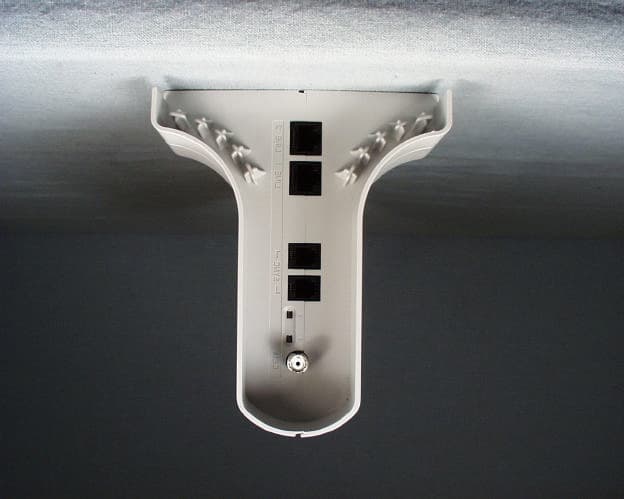
Click to zoom
Application Details
- Equipment Class
- DSS - Part 15 Spread Spectrum Transmitter
- Date of Grant
- Mar 21, 2000
- Application Purpose
- Original Equipment
- Date of Application
- Dec 29, 1999
- Equipment Note
- Frequency Hopping Cordless Telephone
- Frequency Range
- 902.00000000 - 928.00000000
- Company
- Nokia of America Corporation
- Country
- United States
Documents & Files
Document Text
Text extracted from the exhibit documents filed with the FCC. Open a document above to read the original.
Users Manual
503-801-190 Comcode 108594409 Issue 1 May 2000 TransTalk ® 9000 Digital Wireless System MDW 9040 Wireless Pocket Phone Installation, Troubleshooting, and Use Copyright © 1997, 1998 by Lucent Technologies. All rights reserved. For trademark, regulatory compliance, and related legal information, see the copyright and legal notices section of this document. MDW 9040 Wireless Pocket Phone Installation, Troubleshooting, and Use, 503-801-190Issue 1, May 2000 ii Copyright and Legal Notices Copyright Copyright © 2000 by Lucent Technologies. All rights reserved. Printed in U.S.A. Notice Every effort has been made to ensure that the information in this book was complete and accurate at the time of printing. Information, however, is subject to change. The pictures in this book are for illustrative purposes; your actual hardware may look slightly different. This document was prepared by the Product Publications Department of the Global Learning Solutions Division of Lucent Technologies. U.S. offices are located in Denver, CO; Columbus, OH; Holmdel, NJ; and Basking Ridge, NJ. Federal Communications Commission and Industry Canada (IC) Information For details, see Appendix B. Security Toll fraud, the unauthorized use of your telecommunications system by an unauthorized party (for example, persons other than your company’s employees, agents, subcontractors, or persons working on your company’s behalf), can result in substantial additional charges for your telecommunications services. You are responsible for the security of your system. There may be a risk of toll fraud associated with your telecommunications system. You are also responsible for programming and configuring your equipment to prevent unauthorized use. Your system administrator should read all documents provided with this product to fully understand the features that can introduce the risk of toll fraud and the steps that can be taken to reduce that risk. Lucent Technologies does not warrant that this product is immune from or will prevent unauthorized use of common-carrier telecommunication services or facilities accessed through or connected to it. Lucent Technologies will not be responsible for any charges that result from such unauthorized use. Trademarks DEFINITY, MERLIN, MERLIN LEGEND, PARTNER, and TransTalk are registered trademarks of Lucent Technologies; MERLIN MAGIX is a trademark of Lucent Technologies. Supra is a registered trademark of Plantronics, Inc. Warranty Lucent Technologies provides a limited warranty for this product; see Appendix A. Ordering Information The order number for this book is 503-801-190. To order additional copies of these reference materials, call 1-800-457-1235 or 317-322-6791. To order parts and accessories, see Appendix D, “Ordering Replacement and Optional Parts.” Customer Support Follow the procedure you normally use to obtain support for your communications system. Outside the continental U.S., contact your Lucent Technologies Representative or local Authorized Dealer. Copyright and Legal NoticesImportant Safety Instructions MDW 9040 Wireless Pocket Phone Installation, Troubleshooting, and Use, 503-801-190iii Issue 1, May 2000 Important Safety Instructions This book contains instructions related to safety labels on the product: WAR NING: ! WARNING indicates the presence of a hazard that can cause severe or fatal personal injury If the hazard is not avoided. ! CAUTION: CAUTION indicates the presence of a hazard that will or can cause minor personal injury or property damage if not avoided. This phone is designed to provide trouble-free performance without any special maintenance procedures. To reduce the risk of accidental damage: • Keep the phone in an area free of dust, smoke, and moisture; do not block the air vents by placing objects on top of the radio module. • Do not place the phone or battery charger near a heating duct, radiator, or other heat source, and do not drop or expose it to excessive shock or vibration. • Unplug the battery charger, radio module, or carrier if its power cord is damaged, if liquid is spilled into it, or if its housing becomes cracked or otherwise damaged. • To clean your phone, wipe the outside housing with a soft, dust-free cloth. If absolutely necessary, you may use a cloth slightly dampened with a mild soap- and-water solution. Dry quickly with a soft cloth. ! CAUTION: Your phone contains sensitive electronic parts. Never submerge it in any kind of liquid, and never use liquid or aerosol cleaners, detergents, alcohols, solvents, abrasive cleaners, or an excessive amount of water when cleaning the housing and faceplate. To do so could result in irreparable damage. WAR NING: ! Installation of this equipment for In-Range Out of Building (IROB) conditions requires the use of protectors. See the documentation that came with your communications system for more information. ! CAUTION: This equipment is for installation on Lucent Technologies PARTNER, PARTNER Plus, PARTNER II, PARTNER Advanced Communications System, MERLIN, MERLIN Plus, MERLIN II, MERLIN LEGEND, MERLIN MAGIX, and DEFINITY Communications Systems only. For your own safety, follow these rules before or while using your phone: • Before using this product, read and understand all warnings and instructions. • Observe all warnings and instructions marked on this product. Important Safety Instructions Copyright and Legal Notices MDW 9040 Wireless Pocket Phone Installation, Troubleshooting, and Use, 503-801-190Issue 1, May 2000 iv • Do not use this phone in the vicinity of a suspected gas leak. This product is not approved for use in areas labeled by the Occupational Safety and Health Administration (OSHA) as “explosive environments.” Only “Explosive Atmosphere Telephones” may be used in such hazardous environments. • This product should be serviced by a qualified service center when service or repair work is required. Do not open the product or push objects through housing slots. There are no user-serviceable com…
Text truncated - open the document above for the full version.
Users Manual
COMMUNICATION CERTIFICATION LABORATORYTEST REPORT: 73-6951 FCC ID: AS5LITMDW9H Page 83 of 106 Exhibit 8 Exhibit 8: User’s Manual The compliance statement for the MDW 9040 RF Exposure requirements is located on page 4 of the manual as shown below:
Cover Letter(s)
COMMUNICATION CERTIFICATION LABORATORYTEST REPORT: 73-6951 FCC ID: AS5LITMDW9H Page 104 of 105 Exhibit 13 Exhibit 13: Cover Letters December 30, 1999 FEDERAL COMMUNICATIONS COMMISSION Equipment Authorization Division 7435 Oakland Mills Road Columbia, MD 21046 To Whom It May Concern: Enclosed is a FCC Part 15, Subpart C, Section 15.247 Certification application for the Lucent Technologies, Inc. Model MDW 9040, FCC ID: AS5LITMDW9H Please let me know if I can be of further assistance. Sincerely yours, COMMUNICATION CERTIFICATION LABORATORY Joseph W. Jackson V.P. Marketing COMMUNICATION CERTIFICATION LABORATORYTEST REPORT: 73-6951 FCC ID: AS5LITMDW9H Page 105 of 105 Exhibit 13 Request for Confidentiality Letter
External Photos
COMMUNICATION CERTIFICATION LABORATORYTEST REPORT: 73-6951 FCC ID: AS5LITMDW9H Page 6 of 105 Exhibit 3 Exhibit 3: Photographs of Overall Appearance Front View of the MDW 9040 base. COMMUNICATION CERTIFICATION LABORATORYTEST REPORT: 73-6951 FCC ID: AS5LITMDW9H Page 7 of 105 Exhibit 3 Back View of the MDW 9040 base. COMMUNICATION CERTIFICATION LABORATORYTEST REPORT: 73-6951 FCC ID: AS5LITMDW9H Page 8 of 105 Exhibit 3 Bottom View of the MDW 9040 base. COMMUNICATION CERTIFICATION LABORATORYTEST REPORT: 73-6951 FCC ID: AS5LITMDW9H Page 9 of 105 Exhibit 3 Front View of the MDW 9040 handset. COMMUNICATION CERTIFICATION LABORATORYTEST REPORT: 73-6951 FCC ID: AS5LITMDW9H Page 10 of 105 Exhibit 3 Back View of the MDW 9040 handset with battery installed. COMMUNICATION CERTIFICATION LABORATORYTEST REPORT: 73-6951 FCC ID: AS5LITMDW9H Page 11 of 105 Exhibit 3 Back View of the MDW 9040 handset without battery installed.
ID Label/Location Info
COMMUNICATION CERTIFICATION LABORATORYTEST REPORT: 73-6951 FCC ID: AS5LITMDW9H Page 1 of 105 Exhibit 1 Exhibit 1: FCC ID Label Equipment Identification Label In accordance with the requirements of Sections 15.19 (a), 2.925 and 2.926 of the FCC Rules, the following information will be permanently affixed to the Lucent Technologies, Inc. Model MDW 9040 as shown in the photograph below. The FCC ID number is located on both the base and the handset, but due to the size of the handset the compliance statement is located only on the base. Photograph of the back exterior of the base, showing the label placement. COMMUNICATION CERTIFICATION LABORATORYTEST REPORT: 73-6951 FCC ID: AS5LITMDW9H Page 2 of 105 Exhibit 1 Photograph of label on the back exterior of the base. COMMUNICATION CERTIFICATION LABORATORYTEST REPORT: 73-6951 FCC ID: AS5LITMDW9H Page 3 of 105 Exhibit 1 Photograph of the back exterior of the handset, showing the label placement. COMMUNICATION CERTIFICATION LABORATORYTEST REPORT: 73-6951 FCC ID: AS5LITMDW9H Page 4 of 105 Exhibit 1 Sketch of the label on the back exterior of the handset.
Internal Photos
COMMUNICATION CERTIFICATION LABORATORYTEST REPORT: 73-6951 FCC ID: AS5LITMDW9H Page 84 of 105 Exhibit 9 Exhibit 9: Internal Photographs Component Side of ETR with Shields Installed PCB (Base) COMMUNICATION CERTIFICATION LABORATORYTEST REPORT: 73-6951 FCC ID: AS5LITMDW9H Page 85 of 105 Exhibit 9 Component Side of ETR PCB without Shields Installed (Base) COMMUNICATION CERTIFICATION LABORATORYTEST REPORT: 73-6951 FCC ID: AS5LITMDW9H Page 86 of 105 Exhibit 9 Opposite Side of ETR PCB (Base) COMMUNICATION CERTIFICATION LABORATORYTEST REPORT: 73-6951 FCC ID: AS5LITMDW9H Page 87 of 105 Exhibit 9 Component Side of DCM with Shields Installed PCB (Base) COMMUNICATION CERTIFICATION LABORATORYTEST REPORT: 73-6951 FCC ID: AS5LITMDW9H Page 88 of 105 Exhibit 9 Component Side of DCM PCB without Shields Installed (Base) COMMUNICATION CERTIFICATION LABORATORYTEST REPORT: 73-6951 FCC ID: AS5LITMDW9H Page 89 of 105 Exhibit 9 Opposite Side of DCM PCB (Base) COMMUNICATION CERTIFICATION LABORATORYTEST REPORT: 73-6951 FCC ID: AS5LITMDW9H Page 90 of 105 Exhibit 9 Component Side of PCB with LCD Display (Handset) COMMUNICATION CERTIFICATION LABORATORYTEST REPORT: 73-6951 FCC ID: AS5LITMDW9H Page 91 of 105 Exhibit 9 Component Side of PCB without LCD Display (Handset) COMMUNICATION CERTIFICATION LABORATORYTEST REPORT: 73-6951 FCC ID: AS5LITMDW9H Page 92 of 105 Exhibit 9 Opposite Side of PCB with Shield Installed (Handset) COMMUNICATION CERTIFICATION LABORATORYTEST REPORT: 73-6951 FCC ID: AS5LITMDW9H Page 93 of 105 Exhibit 9 Opposite Side of PCB without Shield Installed (Handset)
RF Exposure Info
COMMUNICATION CERTIFICATION LABORATORYTEST REPORT: 73-6951 FCC ID: AS5LITMDW9H Page 95 of 105 Exhibit 11 Exhibit 11: RF Exposure/Environmental Evaluation Section 15.319 (i) Requirement: Unlicensed PCS devices are subject to the radiofrequency radiation exposure requirements specified in '' 1.1307(b), 2.1091 and 2.1093 of this chapter, as appropriate. All equipment shall be considered to operate in a “general population/uncontrolled” environment. Applications for equipment authorization of devices operating under this section must contain a statement confirming compliance with these requirements for both fundamental emissions and unwanted emissions. Technical information showing the basis for this statement must be submitted to the Commission upon request. Demonstration of Compliance: The base station of the MDW 9040 is classified as a mobile device, which is installed so that a minimum separation distance of 20 centimeters is maintained between the transmitter’s radiating structure and the body of the user or nearby persons, and the ERP of the MDW 9040 is less than 3 watts. The handset of the MDW 9040 is classified as a portable device, which is categorically excluded from routine environmental evaluation for RF exposure. Therefore, the MDW 9040 is categorically excluded from routine environmental evaluation for RF exposure as per ' 2.1091(c) and ' 2.1093(c).
RF Exposure Info
COMMUNICATION CERTIFICATION LABORATORYTEST REPORT: 73-6951 FCC ID: AS5LITMDW9H Page 95 of 106 Exhibit 11 Exhibit 11: RF Exposure/Environmental Evaluation Section 15.247 (b)(4) Requirement: Systems operating under the provisions of this section shall be operated in a manner that ensures that the public is not exposed to radio frequency energy levels in excess of the Commission’s guidelines. See Sec. 1.1307(b)(1) of this chapter. Technical information showing the basis for this statement must be submitted to the Commission upon request. Demonstration of Compliance: Base Station The base station of the MDW 9040 is classified as a mobile device, which is installed so that a minimum separation distance of 20 centimeters is maintained between the transmitter’s radiating structure and the body of the user or nearby persons, and the ERP of the MDW 9040 is less than 1.5 watts. The instruction manual contains the following warning statement on page 4 to ensure the minimum separation distance. “ In order to comply with the FCC RF exposure requirements the MDW 9040 must be installed so that a minimum separation distance of 20 cm be maintained from the antenna to the user or any near by persons.” Handset The maximum measured peak output power of the device was 166.0 mW. The MDW 9040 handset transmits TDD for 1.059 msec (the total frame length is 5.0 msec) on one specific hop channel, then it hops to the next channel in the hop list. The average RF duty factor for the MDW 9040 is -13.5 dB. This factor is derived using the following formula: 20 log 1.059 msec = 20 log 0.2118 = -13.5 dB 5 msec COMMUNICATION CERTIFICATION LABORATORYTEST REPORT: 73-6951 FCC ID: AS5LITMDW9H Page 96 of 106 Exhibit 11 Shown below are the measured output power and the average output power using the above-calculated RF duty cycle: Frequency (MHz) Peak Output Power (dBm) Peak Output Power (mW) Average Output Power (dBm) Average Output Power (mW) 902.2620.0100.06.54.5 915.3622.2166.08.77.4 927.6521.9155.08.46.9 20.0 – 13.5 = 6.5 dBm = 4.5 mW 22.2 – 13.5 = 8.7 dBm = 7.4 mW 21.9 – 13.5 = 8.4 dBm = 6.9 mW Since the peak and average RF output power of the device is less than 200 mW the user is not exposed to excessive amounts of RF; therefore, the device complies with Section 15.247(b)(4) for RF Exposure. Note: The handset antenna is a quarter wave monopole design. In both retracted and extended positions, the maximum gain does not exceed +0dBi.
Test Report
COMMUNICATION CERTIFICATION LABORATORYTEST REPORT: 73-6951 FCC ID: AS5LITMDW9H Page 14 of 105 Exhibit 6 Exhibit 6: Test Report TEST REPORT FROM: COMMUNICATION CERTIFICATION LABORATORY 1940 W. Alexander Street Salt Lake City, Utah 84119-2039 Type of Report: Certification TEST OF: MDW 9040 FCC ID: AS5LITMDW9H To FCC PART 15.247, Subpart C Test Report Serial No: 73-6951 Applicant: Lucent Technologies, Inc. 600 Mountain Avenue Murray Hill, NJ 07974 Date(s) of Test: December 13 – 17, 1999 Issue Date: December 30, 1999 Equipment Receipt Date: December 10, 1999 COMMUNICATION CERTIFICATION LABORATORYTEST REPORT: 73-6951 FCC ID: AS5LITMDW9H Page 15 of 105 Exhibit 6 CERTIFICATION OF ENGINEERING REPORT This report has been prepared by Communication Certification Laboratory to determine compliance of the device described below with the requirements of FCC PART 15.247, Subpart C. This report may be reproduced in full, partial reproduction may only be made with the written consent of the laboratory. The results in this report apply only to the sample tested. -Applicant:Lucent Technologies, Inc. -Manufacturer:Lucent Technologies, Inc. -Brand Name:Trans Talk -Model Number:MDW 9040 -FCC ID:AS5LITMDW9H On this 30 th day of December 1999, I, individually, and for Communication Certification Laboratory, certify that the statements made in this engineering report are true, complete, and correct to the best of my knowledge, and are made in good faith. COMMUNICATION CERTIFICATION LABORATORY Checked by: William S. Hurst, P.E. Vice President Tested by: Roger J. Midgley EMC Engineering Manager COMMUNICATION CERTIFICATION LABORATORYTEST REPORT: 73-6951 FCC ID: AS5LITMDW9H Page 16 of 105 Exhibit 6 SECTION 1. CLIENT INFORMATION AND RESPONSIBLE PARTY: 1.1 Client Information: Company Name: Lucent Technologies, Inc. 600 Mountain Avenue Murray Hill, NJ 07974 Contact Name:Don Webber Title:Member – Technical Staff COMMUNICATION CERTIFICATION LABORATORYTEST REPORT: 73-6951 FCC ID: AS5LITMDW9H Page 17 of 105 Exhibit 6 SECTION 2. EQUIPMENT UNDER TEST (EUT) 2.1 Identification of EUT: Trade Name:Trans Talk Model Name or Number:MDW 9040 Serial Numbers:108487174, 108487158 and 108535998 Options Fitted:None Country of Manufacture:U.S.A. 2.2 Description of EUT: See theory of operation (Exhibit 12). This report covers the transmitter only the receiver is covered under a separate verification report. The base stations can be used with four different Lucent PBX’s. The RF section of the base stations is identical the only difference is in the interface section to the PBX. The DCP works with the DEFINITY, the TDL works with the MERLIN MAGIK, the ATL works with the MERLIN and the ETR works with the PARTNER. The DCP and the TDL use the same interface board and the ETR and ATL use the same interface board. The base station is equipped with a third antenna port (Antenna C) on the bottom of the unit, this port is only used in the factory to set the output power. This port will not be populated during production. 2.3 Modification Incorporated/Special Accessories on EUT: There were no modifications or special accessories required in order to comply with the specification. COMMUNICATION CERTIFICATION LABORATORYTEST REPORT: 73-6951 FCC ID: AS5LITMDW9H Page 18 of 105 Exhibit 6 2.4 EUT and Support Equipment: The FCC ID numbers for all the EUT and support equipment used during the test (including inserted cards) are listed below: Brand Name Model Number Serial No. FCC ID Number DescriptionName of Interface Ports/Interface Cables BN: Trans Talk MN: MDW 9040 SN: 108487174 108487158 108535998 AS5LITMDW9HBase Station and Handset (EUT’s) N/A COMMUNICATION CERTIFICATION LABORATORYTEST REPORT: 73-6951 FCC ID: AS5LITMDW9H Page 19 of 105 Exhibit 6 SECTION 3. TEST SPECIFICATION, METHODS & PROCEDURES 3.1 Test Specification: Title:FCC PART 15.247, Subpart C (47 CFR 15). Limits and methods of measurement of radio interference characteristics of radio frequency devices. Operation within the bands 902-928 MHz, 2400-2483.5 MHz and 5725- 5850 MHz. Purpose of Test: The tests were performed to demonstrate Initial compliance. 3.2 Methods & Procedures: 3.2.1 '' 15.247 (a)Operation under the provisions of this section is limited to frequency hopping and direct sequence spread spectrum intentional radiators that comply with the following provisions: (1)Frequency hoping systems shall have hopping channel carrier frequencies separated by a minimum of 25 kHz or the 20 dB bandwidth of the hopping channel, whichever is greater. The system shall hop to channel frequencies that are selected at the system-hopping rate from a pseudorandomly ordered list of hopping frequencies. Each frequency must be used equally on the average by each transmitter. The system receivers shall have input bandwidths that match the hopping channel bandwidths of their corresponding transmitters and shall shift frequencies in synchronization with the transmitting signals. (i)For frequency hopping systems operating in the 902 - 928 MHz band: if the 20 dB bandwidth of the hopping channel is less than 250 kHz, the system shall use at least 50 hopping frequencies and the average time of occupancy on any frequency shall not be greater than 0.4 seconds within a 20 second period; if the 20 dB bandwidth of the hopping channel is 250 kHz or greater, the system shall use at least 25 hopping frequencies and the average time of occupancy on any frequency shall not be greater than 0.4 seconds within a 10 second period. The maximum allowed 20 dB bandwidth of the hopping channel is 500 kHz. COMMUNICATION CERTIFICATION LABORATORYTEST REPORT: 73-6951 FCC ID: AS5LITMDW9H Page 20 of 105 Exhibit 6 (ii)Frequency hopping systems operating in the 2400 – 2483.5 MHz and the 5725 – 5850 MHz bands shall use at least 75 hopping frequencies. The maximum allowed 20 dB bandwidth of the hopping channel is 1 MHz. The average time of occupancy on any frequency shall not be greater than 0.4 seconds within a 30 second period. (2)For dire…
Text truncated - open the document above for the full version.
Test Setup Photos
COMMUNICATION CERTIFICATION LABORATORYTEST REPORT: 73-6951 FCC ID: AS5LITMDW9H Page 79 of 105 Exhibit 7 Exhibit 7: Test Set-Up Photographs Front view of worst case radiated emissions (Base) COMMUNICATION CERTIFICATION LABORATORYTEST REPORT: 73-6951 FCC ID: AS5LITMDW9H Page 80 of 105 Exhibit 7 Back view of worst case radiated emissions (Base) COMMUNICATION CERTIFICATION LABORATORYTEST REPORT: 73-6951 FCC ID: AS5LITMDW9H Page 81 of 105 Exhibit 7 Front view of worst case radiated emissions (Handset) COMMUNICATION CERTIFICATION LABORATORYTEST REPORT: 73-6951 FCC ID: AS5LITMDW9H Page 82 of 105 Exhibit 7 Back view of worst case radiated emissions (Handset)
Contact Information
Applicant
Raymond J. Johnson(Technical Manager)
Technical Contact
Communication Certification LaboratoryRoger J Midgley
[email protected](801) 972-6146
1940 W. Alexander Street · Salt Lake City, Utah · United States
Test Firm
Communication Certification Lab.Scott Earl
Technical Specifications
| # | Rule Parts | Frequency Range | Power Output | Tolerance |
|---|---|---|---|---|
| 1 | 15C | 902 MHz - 928 MHz | 166.00 mW | Hz |
Other Applications from Nokia of America Corporation

AS5BBTRX-23
Mar 15, 2015B13 RRH 4X30
Equipment Class
TNB - Licensed Non-Broadcast Station Transmitter
AS5BBTRX-21
Feb 01, 2015PCS LTE 9764 Metro Cell Outdoor Transceiver System
Equipment Class
PCB - PCS Licensed Transmitter
AS5BBTRX-22
Jan 26, 2015B25 RRH 4X30
Equipment Class
PCB - PCS Licensed Transmitter
AS5BBTRX-17
Jan 08, 2014AWS LTE 9764 Metro Cell Outdoor Transceiver System
Equipment Class
TNB - Licensed Non-Broadcast Station Transmitter
AS5BBTRX-14
Dec 18, 20139763 MCI B25 PCS LTE 2x250mW
Equipment Class
PCB - PCS Licensed Transmitter