AS5ONEBTS-04UMTS CDMA Radio (PCS)
Nokia of America Corporation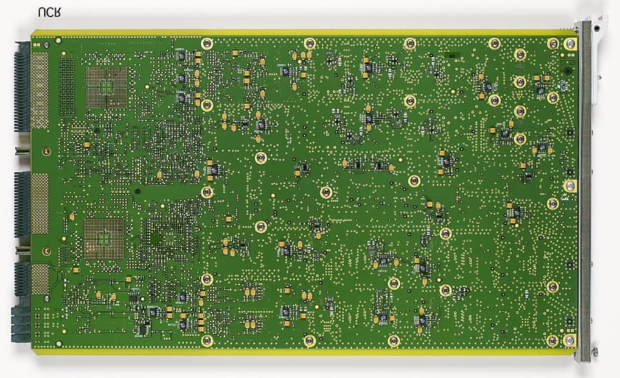
Click to zoom
Application Details
- Equipment Class
- PCB - PCS Licensed Transmitter
- Date of Grant
- Sep 23, 2002
- Application Purpose
- Original Equipment
- Date of Application
- Sep 23, 2002
- Equipment Note
- UMTS CDMA Radio (PCS)
- Frequency Range
- 1930.00000000 - 1990.00000000
- Company
- Nokia of America Corporation
- Country
- United States
Documents & Files
Document Text
Text extracted from the exhibit documents filed with the FCC. Open a document above to read the original.
Cover Letter(s)
APPLICANT: Lucent Technologies Inc. -1 - FCC ID: AS5ONEBTS-04 Lucent Technologies Inc. - Proprietary Use pursuant to Company Instructions. 1 Federal Communications Commission Lucent Technologies Inc. Office of Engineering and Technology 101 Crawfords Corner Road Equipment Authorization Division Holmdel, NJ 07733-3030 Application Processing Branch 7435 Oakland Mills Road Columbia, MD 21046 September 24, 2002 Dear Examiner: In accordance with Parts 2 and 24 of the Commission’s Rules and Regulations, we are submitting herewith, statements and supporting data to show compliance with the requirements of the Commission for Product Certification of the Lucent Technologies Corporation UMTS CDMA Radio (PCS), henceforth UCR , FCC ID: AS5ONEBTS-04 . The UCR is used in Lucent Technologies Corp FLEXENT OneBTS Land Station PCS systems using Code Division Multiple Access (CDMA) technology, for use in Domestic Personal Communication Services. This application for the UCR under FCC ID: AS5ONEBTS-04, is for operation in the domestic Personal Communication Service band with a CDMA signal. The data summarized below is in the form presently used by the Commission’s Radio Equipment List. ManufacturerLucent Technologies, Inc. Equipment Identification AS5ONEBTS-04 Rules Part Number24 (E) Frequency Range1930 -1990 MHz PCS Band Output Power-25 dBm (.003mW) to +10dBm (10mW) Varied by Software (Maximum RF Power output for single carrier, or composite RF power output for two or three carrier is 10 dBm) Frequency Tolerance+/- 0.05 ppm Emission Designator1M25F9W The UCR , under FCC ID: AS5ONEBTS-04 is designed to be operated and marketed with CDMA transmit equipment that was Product Certified in accordance with Parts 2 and 24 of the Code. When utilized in normal PCS base station operation, the UCR will be operated with a FCC Product Certified power amplifier. The overall performance of the integrated equipment shall continue to be compliant with FCC requirements. The UCR is designed to transmit one, two, or three contiguous 1.25 MHz CDMA channels. The UCR , at its output, is typically operated over the power range of –20 dBm to +5 dBm for each of the 1.25 MHz CDMA carriers in a single, dual, or three channels configuration. The total power is APPLICANT: Lucent Technologies Inc. -2 - FCC ID: AS5ONEBTS-04 Lucent Technologies Inc. - Proprietary Use pursuant to Company Instructions. 2 limited to +10.0dBm per channel (+10 dBm total integrated power for 3 or 2 carriers) for each of the 1.25 MHz CDMA carriers in a single, dual, or three channels configuration and is the level for this application. The actual power level delivered by the UCR to transmit amplifier is under the software control of the Mobile Switching Center of the local Cellular/PCS system. The output of this unit in normal base station use, is always subjected to additional signal amplification and post amplification filtering as required for spurious control prior to connection to the (J4) antenna connector. The software control only allows for adjustment in power necessary to provide the rated maximum of the co-configured transmitter The evaluation of the "Spurious emissions at antenna terminals" (Sec. 2.1051) were made with a kLAM/AS5ONEBTS-02 and its associated filters. This kLAM was also used for the "Field strength of spurious radiated" (Sec. 2.1053) measurements. Wherever possible the test procedures defined in 47CFR Part's 2(J) and 24(E) were followed. Because of the "state of the art" nature of this equipment some of the characteristics cannot be tested using the requirements in 47CFR , so for those characteristics EIA/TIA-IS-97-D was used to define the tests and evaluation criteria used in this application. This application for UCR/FCC ID:AS5ONEBTS-04, is for the entire PCS band. Since the application encompasses the single, dual and three carrier configurations it presents the required test data for each of those operational configurations. The RF power, modulation, and bandwidth of the UCR transmit signal output are defined and controlled by software The UCR /AS5ONEBTS-04 is produced by Lucent Technologies Incorporated solely for incorporation into Lucent Technologies Inc. products. These attached exhibits contain the technical data, and the required statements and documents for Product Certification. The technical contact at Lucent Technologies will comply with any request for additional information should the need arise. Sincerely, Dheena Moongilan Distinguished Member of Technical Staff Global Product Compliance Laboratory phone: (732) 332-6003 email: [email protected] APPLICANT: Lucent Technologies Inc. -3 - FCC ID: AS5ONEBTS-04 Lucent Technologies Inc. - Proprietary Use pursuant to Company Instructions. 3 TABLE OF CONTENTS COVER LETTER Cover Letter Letter for Confidential Treatment of Exhibits ATTESTATION STATEMENT Section 2.911 (d)Qualifications and Certifications Section 2.1033 (c) (1,2)Manufacturers, Identification Section 2.1033 (c) (4-7)Emissions, Frequency Range, Power Level USERS MANUAL Section 2.1033 (c) (3)Users Manual Section 2.1033 (c) (9)PARTS LIST/TUNE-UP PROCEDURE Tune-Up Procedure Section 2.1033 (c) (13)OPERATIONAL DESCRIPTION Description of Modulation System Section 2.1033 (c) (11) and 2.925 (a) (1) ID LABEL/LOCATION INFORMATION Drawing of FCC ID Section 2.1033 (c) (12) EXTERNAL PHOTOS External Photos Section 2.1033 (c) (8) TEST REPORT Measurement of DC Power Section 2.1033 (c) (14)Listing of Required Measurements Section 2.1046Measurement of Radio Frequency Power Output Section 2.1047Measurement of Modulation Characteristics Section 2.1049 and Section 24.238 (b) Measurement of Occupied Bandwidth Section 2.1051 Measurement of Spurious Emissions at Antenna Section 2.1053 Field Strength of Spurious Radiation Section 2.1055Measurement of Frequency Stability Section 2.1057Frequency Spectrum to be Investigated APPLICANT: Lucent Technologies Inc. -4 - FCC ID: AS5ONEBTS-04 Lucent Technologies Inc. - Proprietary Use pursuant…
Text truncated - open the document above for the full version.
External Photos
APPLICANT: Lucent Technologies Inc. FCC ID: AS5ONEBTS-04 Lucent Technologies Inc. – Proprietary Use pursuant to Company Instructions PHOTOGRAPH OF CONSTRUCTION SECTION 2.1033 (c) (12) (External Photos) (Lucent Technologies Confidential Proprietary Information) APPLICANT: Lucent Technologies Inc. FCC ID: AS5ONEBTS-04 Lucent Technologies Inc. – Proprietary Use pursuant to Company Instructions PHOTOGRAPH OF CONSTRUCTION SECTION 2.1033(c) (12) Photographs (8” x 10”) of the equipment of sufficient clarity to reveal equipment construction and layout, including meters, if any, and labels for controls and meters and sufficient views of the internal construction to define component placement and chassis assembly. Insofar as these requirements are met by photographs or drawings contained in instruction manuals supplied with the certification request, additional photographs are necessary only to complete the required showing. RESPONSE: Equipment construction, layout, including meters, and labels for control are indicated in Installation, Test and Operational Manual (see Section on “Users Manual”). Internal photographs are included in the Section Internal Photos. Following additional external photographs are included: 1. Photograph of UCR front 2. Photograph of UCR Rear APPLICANT: Lucent Technologies Inc . FCC ID: AS5ONEBTS-04 Lucent Technologies Inc. – Proprietary Use pursuant to Company Instructions Figure 1.Photograph of UCR front APPLICANT: Lucent Technologies Inc . FCC ID: AS5ONEBTS-04 Lucent Technologies Inc. – Proprietary Use pursuant to Company Instructions Figure 2. Photograph of UCR Rear
ID Label/Location Info
APPLICANT: Lucent Technologies Inc. FCC ID: S5ONEBTS-04 Lucent Technologies Inc. – Proprietary Use pursuant to Company Instructions DRAWING OF FCC ID SECTION 2.1033(c) (11) also SECTION 2.925 (a) (1) APPLICANT: Lucent Technologies Inc. FCC ID: S5ONEBTS-04 Lucent Technologies Inc. – Proprietary Use pursuant to Company Instructions SECTION 2.1033(c) (11) also SECTION 2.925 (a) (1) A photograph or drawing of the equipment identification plate or label showing the information to be placed thereon. RESPONSE: 1. Computer drawing of the equipment identification label is included. 2. Photograph of FCC ID Label on UMTS CDAMA Radio is included. UMTS CDMA Radio (PCS) 848919353 PART NO : FCC ID : BNJ27 AS50NEBTS-04 UMTS CDMA Radio (PCS) 848919353 PART NO : FCC ID : BNJ27 AS50NEBTS-04 1 1 Title: Designer: Drawn: Checked: Approved: Job No.: Date: Date: Date: Comcode: Issue#: Client: Finish: Material: Date: Work#: Graphics rear print Black on Lucent OS11150 Central Office White. Serigraph Inc. 3801 E. Decorah Road West Bend, Wisconsin 53095 ■ ■ Graphic Services, Product Marking Group ■ 973.702.2325 ■ 919353 FCC Label jr sj sj PM-0802-160 9/3/02 9/3/02 9/4/02848919353 Flexent CDMA Microcell - J.Reinoso 919353 FCC Label Flexent CDMA Microcell Comcode #: 848919353 Issue #: 1 SPEC DRAWING IS FOR REFERENCE ONLY: DO NOT USE FOR REPRODUCTION 1.52 Radius Typical Text is 10pt Helvetica Med. Text is 8pt Helvetica Med. Logo is 12 pt. in Height Text is 10pt Frutiger Roman ORIGINAL ART: USE FOR REPRODUCTION All Dims shown are in Millimeters .010 Polycarbonate, matte finish over clear with combination .0045 to .005 inch acrylic adhesive 1.5 pt. Rule 66.55 25.4 APPLICANT: Lucent Technologies Inc. FCC ID: AS5ONEBTS-04 Photograph of FCC ID affixed on the AS5ONEBTS-04A
Operational Description
PPLICANT: Lucent Technologies Inc. FCC ID: AS5ONEBTS-04 DESCRIPTION OF MODULATION SYSTEM SECTION 2.1033(c) (13) PPLICANT: Lucent Technologies Inc. FCC ID: AS5ONEBTS-04 DESCRIPTION OF MODULATION SYSTEM SECTION 2.1033 (c) (13) For equipment employing digital modulation techniques, a detailed description of the modulation system to be used, including the response characteristics (frequency, phase and amplitude) of any filters provided, and a description of the modulating wave-train, shall be submitted for the maximum rated conditions under which the equipment will be operated. RESPONSE : The UMTS CDMA Radio (PCS) (UCR) employs Code Division Multiple Access (CDMA) modulation techniques. The modulation descriptions are specified by IS95 and IS97. The CDMA Radio Frequency and digital board (BNJ27) circuits control the functions of UCR. Descriptions of these circuits are included in the submittal of Schematics, for which confidential status has been requested.
Parts List/Tune Up Info
APPLICANT: Lucent Technologies Inc. FCC ID: AS5ONEBTS-04 1 Lucent Technologies Inc. – Proprietary Use pursuant to Company Instructions TUNE-UP PROCEDURE SECTION 2.1033 (c) (9) APPLICANT: Lucent Technologies Inc. FCC ID: AS5ONEBTS-04 2 Lucent Technologies Inc. – Proprietary Use pursuant to Company Instructions TUNE-UP PROCEDURE SECTION 2.1033 (c) (9) Tune-up procedure over the power range, or at specific operating power levels. RESPONSE : There are no specific user tune-up procedures for either power levels or frequency. During normal operation software controls the power level from –25dBm to +10dBm.
Test Report
APPLICANT: Lucent Technologies Inc. FCC ID: AS5ONEBTS-04 LISTING OF REQUIRED MEASUREMENTS SECTION 2.1033 (c) (14) APPLICANT: Lucent Technologies Inc. FCC ID: AS5ONEBTS-04 MEASUREMENT PER SECTION 2.999 OF THE RULES SECTION 2.1033 (c) (14) The data required by Section 2.1046 through 2.1057, inclusive, measured in accordance with the procedures set out in Section 2.1041. RESPONSE : The following pages include the data required for the Certification of the FCC ID: AS5ONEBTS- 04 measured in accordance with the procedures set out in Section 2.999 of the Rules. Each required measurement and its corresponding exhibit number are: Measurement: 1Section 2.1046RF Power Output Measurement: 2Section 2.1047Modulation Characteristics Measurement: 3Section 2.1049Occupied Bandwidth Measurement: 4Section 2.1051Spurious Emissions at Antenna Terminals Measurement: 5Section 2.1053Field Strength of Spurious Radiation Measurement: 6Section 2.1055Measurement of Frequency Stability Section 2.1057Frequency Spectrum to be Investigated . . . . . . . . . . . . . . . . . Test Instrumentation List
Test Report
APPLICANT: Lucent Technologies FCC ID: AS5ONEBTS-04 Lucent Technologies – Proprietary Use pursuant to Company Instructions MEASUREMENT OF DC POWER SECTION 2.1033 (c) (8) APPLICANT: Lucent Technologies FCC ID: AS5ONEBTS-04 Lucent Technologies – Proprietary Use pursuant to Company Instructions Measurement of DC Power SECTION 2.1033 (c) (8) The DC voltages applied to and DC currents into the several elements of the final radio frequency amplifying device for normal operation over the power range. RESPONSE : The UMTS CDMA Radio (UCR) (PCS) outputs 10dBm max. The Final drive stage of the UCR is a microwave integrated circuit. The UCR has the following voltage and maximum current. Final output drive stage: The final state output drive stage draws 11mA at 7.2 V DC.
Test Report
APPLICANT: Lucent Technologies FCC ID:AS5ONEBTS-04 Lucent Technologies – Proprietary Use pursuant to Company Instructions Measurement: 1 MEASUREMENT OF RADIO FREQUENCY POWER OUTPUT Section 2.1046 APPLICANT: Lucent Technologies FCC ID:AS5ONEBTS-04 Lucent Technologies – Proprietary Use pursuant to Company Instructions SECTION 2.1046 Measurement: 1 MEASUREMENT OF RADIO FREQUENCY POWER OUTPUT The test arrangements used to measure the radio frequency power output of the UMTS CDMA Radio (PCS) (UCR) FCC ID: AS5ONEBTS-04, is on the following page. Required measurements were made respectively for single, two and three carriers (channels) where occupied Bandwidth measurements must be performed. The use of the UCR is for a single or multiple CDMA carriers. This requires that the RF power output level be calibrated for the specific channels of use. The test configuration, Figure 1A, allowed the measurement of RF output power for channels investigated for Occupied Bandwidth. These included the upper, and lower band edges and at the center channels for 15MHz wide frequency blocks and upper, and lower band edge channels for 5 MHz wide frequency blocks. The IS-97 channel allocations are listed below: IS 97 channel allocation consists of following channel Blocks: Valid CDMA Channel s & Frequency Range BlockFrequency Bands Per FCC 24.229 MHz Channel No.MHz A (15 MHz )1930.000 – 1945.000 25 – 2751931.250 – 1943.750 D (5 MHz)1945.000 – 1950.000325 – 3751946.250 – 1948.750 B (15 MHz)1950.000 – 1965.000425 – 6751951.250 – 1963.750 E (5 MHz)1965.000 – 1970.000725 – 7751966.250 – 1968.750 F (5 MHz)1970.000 – 1975.000825 – 8751971.250 – 1973.750 C (15 MHz)1975.000 – 1990.000925 - 11751976.250 – 1988.750 The edge channels are 25 and 1175. The UCR has a maximum RF power output of 0.01 Watts (10dBm) +2/-4 dB, it also has a minimum power output at the antenna terminals of 0.003mWatts (-25dBm) +2/-4 dB, across the PCS band (1930-1990 MHz). The signal applied to the PCBR is defined in Table 1.1. The power was reset to 10dBm at each measurement frequency to verify the spectral performance at that power level. The attenuation range was also verified. The specific Frequencies and channels and set power level was documented on each “Occupied Bandwidth” sheet. (see Measurement-3) APPLICANT: Lucent Technologies FCC ID:AS5ONEBTS-04 Lucent Technologies – Proprietary Use pursuant to Company Instructions TypeNumber of Channels Fraction of Power (Linear) Fraction of Power (dB) Comments Pilot10.2000-7.0Walsh 0 Sync10.0471-13.3Walsh 32, always 1/8 rate Paging10.1882-7.3Walsh 1, full rate only Traffic6 0.09412 each -10.3 each Variable Walsh Assignments, full rate only TABLE 1.1 BASE STATION TEST MODEL, NOMINAL TEST SETUP FOR MEASUREMENT OF RADIO FREQUENCY POWER OUTPUT EQUIPMENT: CabinetFlexent One BTS Modcell 4.0 Outdoor UCR:UMTS CDMA Radio (PCS) (FCCID:AS5ONEBTS-04) Flexent PA Power Amplifier (FCCID: AS5ONEBTS-02) Transmit Filter:PCS Band Transmit Filter appropriate for the investigated Band Directional Coupler:HP 778D Dual Directional Coupler Power Meter:HP 437B with HP 8481A Power Head Plotter:HP Model 520 DeskJet Spectrum Analyzer:Rohde & Schwarz FSEK EMI Test Receiver RESULTS : The UMTS CDMA Radio (PCS) (UCR) (FCCID:AS5ONEBTS-04) was configured in the test setup shown in Figure 1A. For each of the PCS channel and channel groups tested the UCR delivered a 10 dBm when measured at the RF output connection. This data is recorded on the Occupied Bandwidth Data Sheets (see Measurement : 3). APPLICANT: Lucent Technologies FCC ID: AS5ONEBTS-04 Lucent Technologies – Proprietary Use pursuant to Company Instructions UCR AS5ONEBTS-04 Flexent PA AS5ONEBTS-0 2 Transmit Filter Output Input Input Output Port J4 Output dBm H-P 437BPower Meter Figure 1A. TEST CONFIGURATION FOR RF POWER OUTPUT Rohde & Schwarz Model FSEKEMI Test Receiver / Spectrum Analyzer Reflected Incident Power Sensor CalibratedAttenuation CalibratedAttenuation HP-778D or 772D Directional Coupler Test Port Lucent Technologies Inc. - Proprietary Use pursuant to Company Instruictions APPLICANT: Lucent Technologies FCC ID: AS5ONEBTS-04 Unit Under Test Test Coupler All components are calibrated over the frequency range of interest Flexent One BTS Modcell 4.0 Outdoor Cabinet
Test Report
APPLICANT: Lucent Technologies- 1 FCC ID: AS5ONEBTS-04 Lucent Technologies – Proprietary Use pursuant to Company Instructions Measurement -2 MEASUREMENT OF MODULATION CHARACTERISTICS SECTION 2.1047 APPLICANT: Lucent Technologies- 2 FCC ID: AS5ONEBTS-04 Lucent Technologies – Proprietary Use pursuant to Company Instructions MEASUREMENT- 2 MEASUREMENT OF MODULATION CHARACTERISTICS SECTION 2.1047 The modulation methods used in CDMA are completely different from those used in FM analog System. The methods used in evaluating the UMTS CDMA Radio (PCS) (UCR) are described in the EIA/TAIS document TIA/EIA-97-C “recommended Minimum performance Standards for Base Stations Supporting Dual-Mode Wideband Spread Spectrum Cellular Mobile Stations”. The modulation quantify criteria are as follows: 1.0Modulation Requirements – Section 4.3 of TIA/EIA-97-C Waveform specifications are tested by measuring the waveform quality of ρ , as defined in TIA/EIA-97-C Section 4.3.2, and code domain power as defined in 4.4.4 Transmit waveform quality can be viewed as the output of a normalized matched filter. The range of values for the transmit waveform quality is from 1.0 for a perfect CDMA waveform to 0.0 for a non-CDMA signal. As an example, the base station with a 0.5 dB degradation in its transmit waveform would have a quality, ρ , of 0.89. 1.1Required Results Section 4.3.2.3 of TIA/EIA-97-C “The normal cross correlation coefficient, ρ , shall be greater than 0.912 (excess power < 0.4 dB)”. The test method and diagrams are taken from TIA/EIA-97-C Section 4 and 6. The signal applied to UCR is as shown in Table. TypeNumber of Channels Fraction of Power (Linear) Fraction of Power (dB) Comments Pilot10.2000-7.0Walsh 0 Sync10.0471-13.3 Walsh 32, always 1/8 rate Paging10.1882-7.3 Walsh 1, full rate only Traffic6 0.09412 each -10.3 each Variable Walsh Assignments, full rate only TABLE 2.1 Base Station Test Model, Nominal 1.3Minimum Standard The normalized cross correlation coefficient, ρ , shall be greater than 0.912 (excess power < 0.4 dB). APPLICANT: Lucent Technologies- 3 FCC ID: AS5ONEBTS-04 Lucent Technologies – Proprietary Use pursuant to Company Instructions The measurement is made with HP VSA Transmitter Tester for RF output power of UCR. 1.4Results The test verified that the waveform quality factor, the normalized cross correlation coefficient, ρ , is ≥ 0.96. It also verifies that the frequency assignment is less than (+0.05 PPM) of the frequency assignment.
Test Report
APPLICANT: Lucent Technologies FCC ID:AS5ONEBTS-04 Measurement: 3 MEASUREMENT OF OCCUPIED BANDWIDTH SECTION 2.1049 APPLICANT: Lucent Technologies FCC ID:AS5ONEBTS-04 SECTION 2.1049 MEASUREMENT: 4 MEASUREMENT OF OCCUPIED BANDWIDTH The occupied bandwidth of the FCC ID: AS5ONEBTS-04 UMTS CDMA Radio PCS (UCR) was measured using a Rohde & Schwarz FSEK Spectrum Analyzer and a HP Model 520 DeskJet Printer. The RF power level was measured using RF power meter as shown in the test setup in Figure 3A. The RF output from the transmitter to spectrum analyzer was reduced (to an amplitude usable by the spectrum analyzer) by using a calibrated attenuator. This attenuation was offset on the display and the signal adjusted to the -16.1dB, -19.1dB, and -20.9dB level for single, two and three carriers respectively corresponding to the corrected RF power level for a 30 kHz resolution bandwidth. The reference-line on the spectrum analyzer display corresponds to level measured by the RF power meter. Occupied Bandwidth plots show measurements made at RF Power output terminals of UCR for an output of 0.01 watts (10 dBm) IS 97 channel allocation consists of following channel Blocks: Valid CDMA Channel s & Frequency Range BlockFrequency Bands Per FCC 24.229 MHz Channel No.MHz A (15 MHz )1930.000 – 1945.000 25 – 2751931.250 – 1943.750 D (5 MHz)1945.000 – 1950.000325 – 3751946.250 – 1948.750 B (15 MHz)1950.000 – 1965.000425 – 6751951.250 – 1963.750 E (5 MHz)1965.000 – 1970.000725 – 7751966.250 – 1968.750 F (5 MHz)1970.000 – 1975.000825 – 8751971.250 – 1973.750 C (15 MHz)1975.000 – 1990.000925 - 11751976.250 – 1988.750 The edge channels are 25 and 1175. The frequencies and channels used for measurements are tabulated on the bottom of each plot. The UCR output signals were plotted at each frequency blocks/bands. Plots are provided for Left Edge, Center and Right Edge of PCS bands A, B and C (Blocks of 15 MHz wide) Plots are provided for Left Edge, and Right Edge of PCS bands D, E and F (Blocks of 5 MHz wide). These frequencies were chosen to show the occupied bandwidth in the channels in each of the PCS bands in which this radio can be operated, in compliance with Section 24.229 and 24.238 (c) of the Commission code. There are no SAT or Wide band data signals associated with CDMA. The signal used to show the occupied bandwidth is defined in Table 3.1. This is the signal recommended in TIA/EIA-97-C. The power output level was adjusted to provide the documented power levels at the bottom of each chart. APPLICANT: Lucent Technologies FCC ID:AS5ONEBTS-04 TypeNumber of Channels Fraction of Power (Linear) Fraction of Power (dB) Comments Pilot10.2000-7.0Walsh 0 Sync10.0471-13.3Walsh 32, always 1/8 rate Paging10.1882-7.3Walsh 1, full rate only Traffic60.09412 each -10.3 each Variable Walsh Assignments, full rate only TABLE 3.1 Base Station Test Model, Nominal The minimum standard presented in TIA/EIA-97-C. “Suppression Inside the Licensee’s Frequency Block(s)” For all frequencies within the base station transmit band of 1930 to 1990 MHz that are within the specific block(s) allocated to the operator’s system. The total conducted spurious emissions in any 30 kHz band greater than 885 kHz for the CDMA channel center frequency shall not exceed a level of –45 dBc.... The spectrum analyzer output plots show the CDMA channel signal is 16.1 dB below the reference line of the spectrum analyzer for the following reason: For the CDMA system there is no carrier without modulation. The CDMA transmit bandwidth is 1.23 MHz. Since spectrum analyzer does not have Resolution Bandwidth setting for 1.23 MHz, the following relationship was used to provide the correct level. 10*log (Resolution Bandwidth/Transmit Bandwidth) = Signal Offset For the peak of the CDMA signal measured with a resolution bandwidth of 30 kHz the signal offset is: Signal Offset for single carrier = 10*log (30 kHz/1.23 MHz) = -16.1 dB Signal Offset for two carrier = 10*log (30 kHz/1.23 x 2 MHz) = -19.1 dB Signal Offset for three carrier = 10*log (30 kHz/1.23 x 3 MHz) = -20.9 dB APPLICANT: Lucent Technologies FCCID: AS5ONEBTS-04 Lucent Technologies – Proprietary Use pursuant to Company Instructions UCR AS5ONEBTS-04 Flexent PA AS5ONEBTS-0 2 Transmit Filter Output Input Input Output Port J4 Output dBm H-P 437BPower Meter Figure 3A. TEST CONFIGURATION FOR MEASUREMENT OF OCCUPIED BANDWIDTH Rohde & Schwarz Model FSEKEMI Test Receiver / Spectrum Analyzer Reflected Incident Power Sensor CalibratedAttenuation CalibratedAttenuation HP-778D or 772D Directional Coupler Test Port Lucent Technologies Inc. - Proprietary Use pursuant to Company Instruictions APPLICANT: Lucent Technologies FCC ID: AS5ONEBTS-04 Unit Under Test Test Coupler All components are calibrated over the frequency range of interest Flexent One BTS Modcell 4.0 Outdoor Cabinet APPLICANT: LUCENT TECHNOLOGIES FCCID: AS5ONEBTS-04 Lucent Technologies – Proprietary Use Pursuant to Company Instructions Measurement – 3 MEASUREMENT OF OCCUPIED BANDWIDTH SECTION 2.1049 UCR OUTPUT APPLICANT: LUCENT TECHNOLOGIES FCCID: AS5ONEBTS-04 Lucent Technologies – Proprietary Use Pursuant to Company Instructions OCCUPIED BANDWIDTH UCR OUTPUT BLOCK A (1930 – 1945 MHz) Single Carrier Left Edge1931.25 MHzChannel 25 Center1937.50 MHzChannel 150 Right Edge1943.75 MHzChannel 275 APPLICANT: LUCENT TECHNOLOGIES FCCID: AS5ONEBTS-04 Lucent Technologies – Proprietary Use Pursuant to Company Instructions APPLICANT: LUCENT TECHNOLOGIES FCCID: AS5ONEBTS-04 Lucent Technologies – Proprietary Use Pursuant to Company Instructions APPLICANT: LUCENT TECHNOLOGIES FCCID: AS5ONEBTS-04 Lucent Technologies – Proprietary Use Pursuant to Company Instructions APPLICANT: LUCENT TECHNOLOGIES FCCID: AS5ONEBTS-04 Lucent Technologies – Proprietary Use Pursuant to Company Instructions OCCUPIED BANDWIDTH UCR OUTPUT BLOCK A (1930 – 1945 MHz) Two Carrier Left Edge(1931.25, 1932.50) MHzChannel 25,50 Additional Combination (1941.25…
Text truncated - open the document above for the full version.
Test Report
APPLICANT: Lucent Technologies FCC ID:AS5ONEBTS-04 MEASUREMENT: 4 SPURIOUS EMISSIONS AT ANTENNA TERMINALS SECTION 2.1051 APPLICANT: Lucent Technologies FCC ID:AS5ONEBTS-04 MEASUREMENT: 4 Section 2.1051 Spurious Emissions at Antenna Terminals Spurious Emissions at the RF Power output terminal of the FCC ID: AS5ONEBTS-04 UMTS CDMA Radio PCS (UCR) was investigated over the frequency range of 0 MHz to the 10 th harmonic of the carrier frequency. The test setup was as described in Figure 4A. Measurements were made using a Rohde & Schwarz FSEK Spectrum Analyzer and a HP Model 520 DeskJet Printer. The RF output from the transmitter was reduced (to an amplitude usable by the spectrum analyzer) by using a calibrated attenuator. The RF power level was continuously monitored via RF Power Meter as shown in the test setup in Figure 4A. The required emission limitation specified in Section 24.238 of the Code was applied to these tests. The applied signal met the recommended characteristics per TIA/EIA-97-C as defined Table 4.1 below. All measurements were made for 0.01Watts (10 dBm) output at UCR RF Power output terminal. Based upon the criterion given in Section 24.238(a) of the Code the required emission limitation is equal to –23.0dBc or – 13dBm. The magnitude of spurious emissions that are attenuated more than 20 dB below the permissible value need not specified (Section 2.1051 and 2.1057 (a) and (c)) in the report. IS 97 channel allocation consists of following channel Blocks: Valid CDMA Channel s & Frequency Range BlockFrequency Bands Per FCC 24.229 MHz Channel No.MHz A (15 MHz )1930.000 – 1945.000 25 – 2751931.250 – 1943.750 D (5 MHz)1945.000 – 1950.000325 – 3751946.250 – 1948.750 B (15 MHz)1950.000 – 1965.000425 – 6751951.250 – 1963.750 E (5 MHz)1965.000 – 1970.000725 – 7751966.250 – 1968.750 F (5 MHz)1970.000 – 1975.000825 – 8751971.250 – 1973.750 C (15 MHz)1975.000 – 1990.000925 - 11751976.250 – 1988.750 Per FCC out of band is any frequency < 1930.000 MHz and > 1990.000 MHz PCS band edge channels are 25 and 1175 and block edge channels are indicated in Table above. The frequencies and channels used for tests were tabulated on the bottom of each plot. Output signals were plotted at each frequency block/bands. Plots were made for Left Edge, Right Edge of each PCS bands A, B and C (Blocks that are 15 MHz wide) and PCS bands D, E and F (Blocks that are 5 MHz wide) for single, and two and three composite channels. According to section 24.238 on any frequency outside a PCS block, power of any emission shall be less than –13dBm. The measurement resolution bandwidth shall be 1 MHz or greater. However, in the 1MHz bands immediately outside and adjacent to the frequency block a APPLICANT: Lucent Technologies FCC ID:AS5ONEBTS-04 resolution bandwidth of at least 1% of emission bandwidth of fundamental emission of the transmitter may be used. The emission bandwidth of signal used in the filing is 1.23MHz and 1% of it is 12.3 kHz. Therefore, measurements up to 1MHz from the block edges the resolution bandwidth shall be greater than 12.3kHz. For all measurements up to 1MHz from the block edges a resolution bandwidth of 30kHz was used. Beyond 1 MHz from the block edges but not exceeding 4 MHz, a resolution bandwidth of 30 kHz was used. At these frequency bands, a tighter spurious emission limit was applied using resolution bandwidth ratio correction-factor. 10 log (30kHz/1000kHz ) = -15.2dBm Therefore adjusted limit at channel edges for frequency bands greater than 1 MHz for 30 kHz resolution bandwidth is (-13dBm – 15.2 dBm) = –28.2 dBm TypeNumber of Channels Fraction of Power (Linear) Fraction of Power (dB) Comments Pilot10.2000-7.0Walsh 0 Sync10.0471-13.3Walsh 32, always 1/8 rate Paging10.1882-7.3Walsh 1, full rate only Traffic6 0.09412 each -10.3 each Variable Walsh Assignments, full rate only TABLE 4.1 Base Station Test Model, Nominal RESULTS : The spectral plot document showed that the spurious emissions at UCR RF power output terminal were less than –13 dBm. APPLICANT: Lucent Technologies FCC ID: AS5ONEBTS-04 dBm H-P 437BPower Meter Figure 4A. TEST CONFIGURATION FOR CONDUCTED SPURIOUS Rohde & Schwarz Model FSEKEMI Test Receiver / Spectrum Analyzer Reflected Incident Peak Input Level= -10 dBm Power Sensor CalibratedAttenuation HP-778D or 772D Directional Coupler Test Port Lucent Technologies Inc. - Propr…
Text truncated - open the document above for the full version.
Contact Information
Applicant
Raymond J. Johnson(Technical Manager)
Technical Contact
Lucent Technologies, Inc.Dheena Moongilan
[email protected]723 332 6003
101 Crawsford Corner Rd. · Holmdel, New Jersey · United States
Test Firm
Alcatel-LucentRichard Lorentzen
Technical Specifications
| # | Rule Parts | Frequency Range | Power Output | Emission | Tolerance |
|---|---|---|---|---|---|
| 1 | 24E | 1.93 GHz - 1.99 GHz | 10.00 mW | 1M25F9W | 0.0018000000 ppm |
Other Applications from Nokia of America Corporation

AS5BBTRX-23
Mar 15, 2015B13 RRH 4X30
Equipment Class
TNB - Licensed Non-Broadcast Station Transmitter
AS5BBTRX-21
Feb 01, 2015PCS LTE 9764 Metro Cell Outdoor Transceiver System
Equipment Class
PCB - PCS Licensed Transmitter
AS5BBTRX-22
Jan 26, 2015B25 RRH 4X30
Equipment Class
PCB - PCS Licensed Transmitter
AS5BBTRX-17
Jan 08, 2014AWS LTE 9764 Metro Cell Outdoor Transceiver System
Equipment Class
TNB - Licensed Non-Broadcast Station Transmitter
AS5BBTRX-14
Dec 18, 20139763 MCI B25 PCS LTE 2x250mW
Equipment Class
PCB - PCS Licensed Transmitter