AS5ONEBTS-06Power Amplifier Module - P2PAM
Nokia of America Corporation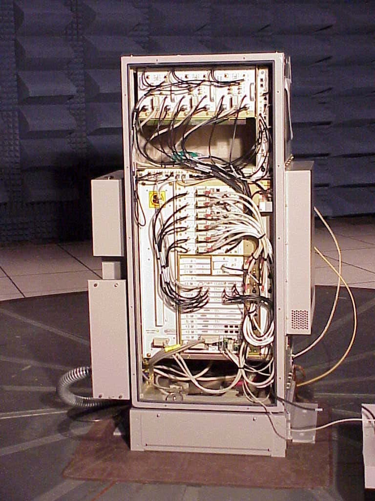
Click to zoom
Application Details
- Equipment Class
- AMP - Amplifier
- Date of Grant
- Oct 15, 2003
- Application Purpose
- Original Equipment
- Date of Application
- Oct 15, 2003
- Equipment Note
- Power Amplifier Module - P2PAM
- Frequency Range
- 1931.25000000 - 1988.75000000
- Company
- Nokia of America Corporation
- Country
- United States
Documents & Files
Document Text
Text extracted from the exhibit documents filed with the FCC. Open a document above to read the original.
External Photos
APPLICANT: Lucent Technologies Exhibit10 FCC ID: AS5ONEBTS-06 Exhibit 10 Section 2.1033 (c)(12) PHOTOGRAPHS OF EQUIPMENT Photographs (8 x 10) of the equipment of sufficient clarity to reveal equipment construction and layout, including meters, if any, and labels for controls and meters and sufficient views of the internal construction to define component placement and chassis assembly. Insofar as these requirements are met by photographs or drawings contained in instruction manuals supplied with the certification request, additional photographs are necessary only to complete the required showing. Response: The following pages contain the required photographs of the P2PAM AS5ONBTS-06 amplifier, subject of this application, showing the following external views: 1) Front view of the P2PAM 2) Rear view of the P2PAM 3) Side view of the P2PAM 4) Additional Side View with cooling fins 5) Side view with cover removed 6) Front view of the Flexent® OneBTS™ CDMA PCS Modular Cell 4 Compact Page 1 of 7 APPLICANT: Lucent Technologies Exhibit10 FCC ID: AS5ONEBTS-06 AS5ONBTS-06 P2PAM 4 cm Amplifier Front View 22cm Page 2 of 7 APPLICANT: Lucent Technologies Exhibit10 FCC ID: AS5ONEBTS-06 AS5ONEBTS-06 P2PAM Rear View Page 3 of 7 APPLICANT: Lucent Technologies Exhibit10 FCC ID: AS5ONEBTS-06 AS5ONEBTS-06 P2PAM Side View 42 cm Page 4 of 7 APPLICANT: Lucent Technologies Exhibit10 FCC ID: AS5ONEBTS-06 AS5ONEBTS-06 P2PAM Side View with Cooling Fins Page 5 of 7 APPLICANT: Lucent Technologies Exhibit10 FCC ID: AS5ONEBTS-06 AS5ONEBTS-06 P2PAM Side View with cover removed Page 6 of 7 APPLICANT: Lucent Technologies Exhibit10 FCC ID: AS5ONEBTS-06 AS5ONEBTS-06 P2PAM Front view of the Flexent® OneBTS™ CDMA PCS Modular Cell 4 Compact AS5ONEBTS-06 P2PAM Amplifier AS5ONEBTS-04 UCR1900 Radio Page 7 of 7
ID Label/Location Info
APPLICANT: Lucent Technologies Exhibit 9 FCC ID: AS5ONEBTS-06 EXHIBIT 9 Section 2.1033 (c)(11) EQUIPMENT IDENTIFICATION LABEL A photograph of the equipment identification plate or label showing the information to be placed theron. Response: The equipment label affixed to the P2PAM AS5ONEBTS-06 amplifier will contain the following information. The engineering drawing of the label is attached to this exhibit. The photo showing the label placement is given in this exhibit as well. Lucent Technologies Flexent Power Amplifier FCC ID:AS5ONEBTS-06 Page 1 of 3 APPLICANT: Lucent Technologies Exhibit 9 FCC ID: AS5ONEBTS-06 Page 2 of 3 APPLICANT: Lucent Technologies Exhibit 9 FCC ID: AS5ONEBTS-06 Photograph of Label Placement The left side view of the AS5ONEBTS-05 P2PAM amplifier is attached here. Rear AS5ONEBTS-06 Label Placement Front Page 3 of 3
Operational Description
APPLICANT: Lucent Technologies FCC ID: AS5ONEBTS-06 EXHIBIT 2 SECTION 2.1033 (c)(1,2,4-7) INFORMATION OF MANUFACTURER, APPLICANT, IDENTIFIER, EMISSION TYPES, FREQUENCY RANGE, OPERATING POWER RANGE AND MAXIMUM POWER RATING Section 2.1033 (c)(1): NAME AND ADDRESS OF MANUFACTURER AND APPLICANT The full name and mailing address of the manufacturer of the device and the applicant for certification. Response: Manufacturer: Lucent Technologies, Inc. 6200 East Broad Street Columbus, OH 43213-1569 U.S.A. Applicant: Lucent Technologies, Inc. 101 Crawfords Corner Road Holmdel, NJ 07733 U.S.A. Attention: Cynthia S. Donovan Section 2.1033 (c)(2): FCC IDENTIFIER Response: FCC Identifier: AS5ONEBTS-06 Section 2.1033 (c)(4): TYPE OR TYPES OF EMISSION Response: 1M25F9W Section 2.1033 (c)(5): FREQUENCY RANGE Response: Transmit: 1930-1990 MHz Section 2.1033 (c)(6): OPERATING POWER RANGE AND ADJUSTMENT Response: .010-20 watts (CDMA signal), continuous software control Section 2.1033 (c)(7): MAXIMUM POWER RATING Response: 20 Watts per carrier. The P2PAM AS5ONEBTS-06 can transmit only one CDMA carrier. Page 1 of 1
Operational Description
APPLICANT: Lucent Technologies FCC ID: AS5ONEBTS-06 Exhibit 12 Section 2.1033 (c)(13) DESCRIPTION OF THE DIGITAL MODULATION SYSTEM For equipment employing digital modulation techniques, a detailed description of the modulation system to be used, including the response characteristics (frequency, phase and amplitude) of any filters provided, and a description of the modulating wavetrain, shall be submitted for the maximum rated conditions under which the equipment will be operated. Response: Digital modulation is controlled by the Lucent Technologies UMTS CDMA Radio 1900 (UCR1900), FCC ID: AS5ONEBTS-04, granted 24 September 2002. The UCR1900 provides the Quadrature Phase Shift Keying (QPSK) modulation required for CDMA signals. Page 1 of 1 APPLICANT: Lucent Technologies FCC ID: AS5ONEBTS-06 EXHIBIT 13 Section 2.1033 (c)(10): Means for Frequency Stabilization Response: The P2PAM does not contain any frequency determining, frequency conversion or frequency stabilizing circuitry. The frequency stabilization for the CDMA signal is provided by the Lucent Technologies UMTS CDMA Radio 1900 (UCR1900), FCC ID: AS5ONEBTS-04, granted 24 September 2002. Page 1 of 1
Parts List/Tune Up Info
APPLICANT: Lucent Technologies FCC ID: AS5ONEBTS-06 Exhibit 4 Section 2.1033 (c)(8): The dc voltages applied to and the dc currents into several elements of final radio frequency amplifying device for normal operation over the power range. Response The P2PAM amplifier has a normal operating input voltage of 24 VDC, and will operate fully within specifications with an input voltage of 19 VDC to 30 VDC. The amplifier operates at approximately 12% efficiency. The nominal dc voltage and range of dc current input to a single P2PAM is summarized below. Input Voltage Single P2PAM Minimum Single P2PAM Maximum Input Current Input Current +24 Vdc 7.6 Amps dc 20 Amps dc Section 2.1033 (c)(8): Tune-up procedure over the power range, or at specific operating levels. Response: The Lucent Technologies P2PAM can not be “tuned-up” by the user. There are no user tune-up Features. All tuning is performed by the manufacturer during, and as part of, the manufacturing Process. Page 1 of 1
RF Exposure Info
APPLICANT: Lucent Technologies FCC ID: AS5ONEBTS-06 EXHIBIT 7 Section 1.033 (c)(10) CIRCUITRY AND DEVICES FOR SUPPRESSION OF SPURIOUS RADIATION A description of all circuitry and devices provided for suppression of spurious radiation. Response: The P2PAM AS5ONEBTS-06 amplifier was designed in adherence to proper Electromagnetic Compatibility (EMC) guidelines and RF shielding to significantly suppress inter-modulation harmonics, carrier induced harmonics and other spurious signals as well as the emissions radiated from them. The suppression of spurious radiation form the P2PAM was achieved by the following two techniques: 1. Proper grounding and shielding of the circuitry and device. 2. Proper filtering in the amplifier unit. Page 1 of 1
Test Report
APPLICANT: Lucent Technologies Exhibit 14 FCC ID: AS5ONEBTS-06 EXHIBIT 14 Test Report This test report presents the measurement data required by the Commission for certifying the AS5ONEBTS-06 P2PAM PCS Power Amplifier Module, subject of this application. All testing was performed during the period of September 2 ~ October 14, 2003. The measurement results have demonstrated the AS5ONEBTS-05 P2PAM amplifier is in full compliance with the Rules of Commission. For some of the required measurements where FCC Parts 2 and 24 did not give specific requirements, TIA/EIA-97-D requirements were used in the report, which are almost identical to the 3GPP2 C.S0010-A v1.0 requirements. Page 1 of 15 APPLICANT: Lucent Technologies Exhibit 14 FCC ID: AS5ONEBTS-06 SUBEXHIBIT 14.1 Section 2.1033 (c)(14) REQUIRED MEASUREMENT DATA The required measurement data is presented in the following exhibits as follows: SUBEXHIBIT 12.2 Section 2.1046 Measurements Required: RF Power Output SUBEXHIBIT 12.3 Section 2.1047 Measurements Required: Modulation Characteristics SUBEXHIBIT 12.4 Section 2.1049 Measurements Required: Occupied Bandwidth SUBEXHIBIT 12.5 Section 2.1051 Measurements Required: Spurious Emissions at Antenna Terminal SUBEXHIBIT 12.6 Section 2.1053 Measurements Required: Field Strength of Spurious Radiation Page 2 of 15 APPLICANT: Lucent Technologies Exhibit 14 FCC ID: AS5ONEBTS-06 SUBEXHIBIT 14.2 Section 2.1046 MEASUREMENT REQUIRED: RF POWER OUTPUT This test is a measurement of the RF power level transmitted at the Lucent Technologies P2PAM AS5ONEBTS-06 end antenna connector (EAC), as shown in the accompanying test set-up diagram. The P2PAM with UCR1900 was set-up with CDMA carrier as follows (table 13.2.1). Table 14.2.1. Base Station Test Model, Nominal Type Number of Channels Fraction of Power (linear) Fraction of Power (dB) Comments Pilot 1 0.2000 -7.0 Walsh 0 Sync 1 0.0471 -13.3 Walsh 32, always 1/8 rate Paging 1 0.1882 -7.3 Walsh 1, full rate only Traffic 6 0.09412 each -10.3 each Variable Walsh assignments, full rate only TIA/EIA-97-D, Section 4.3.1.3, specifies that the total power per carrier should remain within +2dB and - 4dB of the manufacturer’s rated power. The channels that were measured are tabulated in the following table (table 14.2.2): Page 3 of 15 APPLICANT: Lucent Technologies Exhibit 14 FCC ID: AS5ONEBTS-06 SUBEXHIBIT 13.2 Continued Table 14.2.2. Results of RF Power Output PCS Chan. No. Frequency (Tx) MHz P2PAM (EAC) Output (dBm) 25 50 75 1931.250 1932.500 1933.750 43.08 42.98 43.01 100 125 150 1935.000 1936.250 1937.500 42.95 43.04 43.08 175 200 225 1938.750 1940.00 1941.250 42.98 43.07 43.02 250 275 1942.500 1943.750 43.02 42.96 325 350 375 1946.250 1947.500 1948.750 42.89 42.90 42.88 425 450 475 1951.250 1952.500 1953.750 42.99 42.92 42.87 500 525 550 1955.000 1956.250 1957.500 42.90 42.95 42.92 575 600 625 1958.750 1960.000 1961.250 42.83 42.87 42.84 650 675 1962.500 1963.750 42.99 42.97 725 750 775 1966.250 1967.500 1968.750 43.02 43.00 42.99 825 850 875 1971.250 1972.500 1973.750 43.04 43.02 43.04 925 950 975 1976.250 1977.500 1978.750 42.93 42.92 42.91 1000 1025 1050 1980.000 1981.250 1982.500 43.02 42.99 42.96 1075 1100 1125 1983.750 1985.000 1986.250 42.87 42.81 42.84 1150 1175 1987.500 1988.750 42.82 42.73 Page 4 of 15 APPLICANT: Lucent Technologies Exhibit 14 FCC ID: AS5ONEBTS-06 SUBEXHIBIT 14.2 Continued Power measurements were made with a Giga-tronics 8542C Universal Power meter with 8061A Power Sensor (0.01-18 GHz) in the modulated average mode. The test set-up for conducting the RF power output measurement form the Lucent Technologies P2PAM AS5ONEBTS-06 is shown in the following figure. All results are given in the above table. It can be seen from the above table that all the mean RF power outputs measured across the PCS band are within +/- 0.28 dB of the rated maximum power of 43.01 dBm (20 watts). Results: The RF power output of the Lucent Technologies P2PAM AS5ONEBTS-06 across the PCS Frequency Band 1930-1990 MHz are in full compliance with the Rules of the Commission TEST SET-UP FOR MEASUREMENT OF RADIO FREQUENCY OUTPUT Figure 14.2.1 Test Set-up for Measurement of Radio Frequency Power Output CDMA PCS Modcell 4 Compact P2PAM FCC ID:AS5ONEBTS -06 UCR1900 FCC ID:AS5ONEBTS -04 Gigatronics 8542C Power Meter With 80621A Power Sensoe Page 5 of 15 APPLICANT: Lucent Technologies Exhibit 14 FCC ID: AS5ONEBTS-06 SUBEXHIBIT 14.3 Section 2.1049 MEASUREMENT REQUIRED: OCCUPIED BANDWIDTH In compliance with Section 2.1049(h), a single CDMA carrier was configured with a combination of Pilot, Paging, Sync and Traffic channels. The Pilot/Paging/Sync channels were setup according to the recommended test model for base stations given in TIA/EIA-97-D (Section 6), as shown in Table 13.2.1. The occupied bandwidth measurements were made at the end antenna connector (EAC) of the P2PAM on twelve (12) channels which correspond to the highest and lowest channels in each of the six PCS bands (A,D,B,E,F and C). At each of the above twelve frequencies, the carrier power level at the EAC of the P2PAM was adjusted to the maximum rated power of 43.01 dBm (20 watts). The emission limitations and the setting of the measurement equipment for the occupied bandwidth measurement of a 1.23 MHz CDMA PCS carrier specified in Appendix A, Section 10 of FCC 02-229 Report and Order. The FCC requirements are tabulated in the following table: Table 14.3.1 FCC Part 24.238 Spurious Emission Limits Displacement from the Carrier Center Frequency f c Required Minimum Attenuation below the Mean Carrier Power P=43.01dbm Resolution Bandwidth of Spectrum Analyzer 885 kHz < |f – f c | ≤ 1.25 MHz 45 dBc 30 kHz 1.25 MHz < |f – f c | ≤ 1.98 MHz 52.21 dBc (note 1) 30 kHz Block edge to < 4 MHz 71.21 dBc (note 2) 30 kHz Note 1 – The 52.21 dBc level was derived from -{43+10log(mean power in watts)} = -13 dBm When measured in a resolution bandwidth not less than 1% carrier signal. Since carrier is a 1.25 MHz bandwidth signal, the li…
Text truncated - open the document above for the full version.
Contact Information
Applicant
Raymond J. Johnson(Technical Manager)
Test Firm
Alcatel-LucentRichard Lorentzen
Technical Specifications
| # | Rule Parts | Frequency Range | Power Output | Emission |
|---|---|---|---|---|
| 1 | 24 | 1.93 GHz - 1.99 GHz | 20 W | 1M25F9W |
Other Applications from Nokia of America Corporation

AS5BBTRX-23
Mar 15, 2015B13 RRH 4X30
Equipment Class
TNB - Licensed Non-Broadcast Station Transmitter
AS5BBTRX-21
Feb 01, 2015PCS LTE 9764 Metro Cell Outdoor Transceiver System
Equipment Class
PCB - PCS Licensed Transmitter
AS5BBTRX-22
Jan 26, 2015B25 RRH 4X30
Equipment Class
PCB - PCS Licensed Transmitter
AS5BBTRX-17
Jan 08, 2014AWS LTE 9764 Metro Cell Outdoor Transceiver System
Equipment Class
TNB - Licensed Non-Broadcast Station Transmitter
AS5BBTRX-14
Dec 18, 20139763 MCI B25 PCS LTE 2x250mW
Equipment Class
PCB - PCS Licensed Transmitter