AS5RWM232V200WAUSWaveACCESS NET 2400 Remote Wireless Modem
Nokia of America Corporation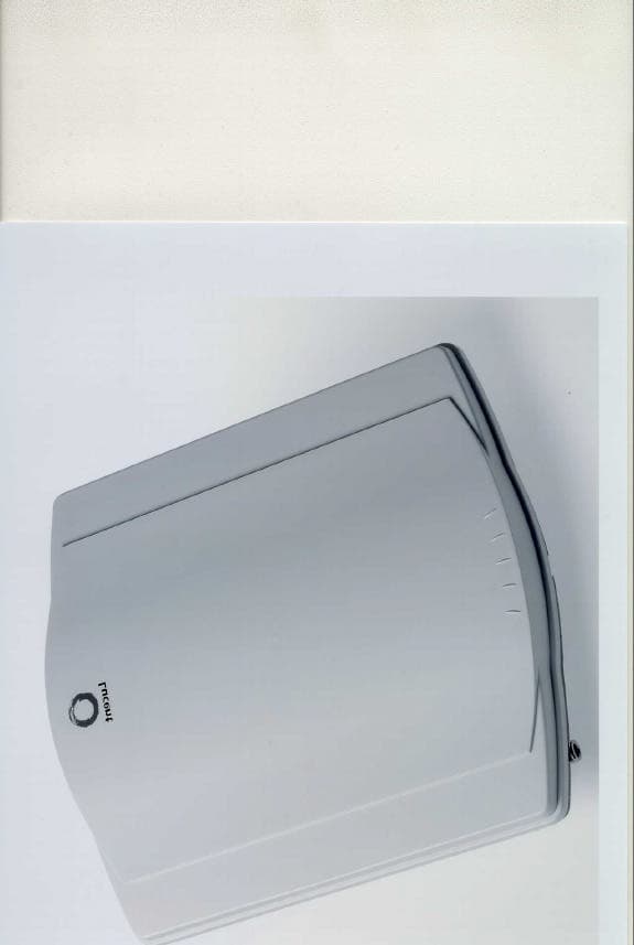
Click to zoom
Application Details
- Equipment Class
- DSS - Part 15 Spread Spectrum Transmitter
- Date of Grant
- Jul 13, 2000
- Application Purpose
- Original Equipment
- Date of Application
- Apr 13, 2000
- Equipment Note
- WaveACCESS NET 2400 Remote Wireless Modem
- Frequency Range
- 2402.00000000 - 2480.00000000
- Company
- Nokia of America Corporation
- Country
- United States
Documents & Files
Document Text
Text extracted from the exhibit documents filed with the FCC. Open a document above to read the original.
Users Manual
APPLICANT: Lucent Technologies FCC ID: AS5RWM232V200WAUS EXHIBIT 3 Installation and Operating Instructions SECTION 2.1033 (a) (3) WaveACCESS NET 2400 Installation Guide1-1 1 Introducing the WaveACCESS NET 2400 System THIS IS AN INCOMPLETE DRAFT. This chapter introduces the WaveACCESS NET product family, including its main features and benefits. In addition, workflows for installing the CU232 and the remote unit are provided. About this chapter:1 Introducing the WaveACCESS NET Product Family, page 1-2, provides an overview of the WaveACCESS NET product family. Features and Benefits, page 1-6, describes the numerous features and benefits that can enhance working environments using wireless systems. WaveACCESS NET Ruggedized Unit, page 1-7, describes the additional features and benefits provided by the ruggedized WaveACCESS NET 2400 units, for outdoor installation. Technical Specifications, page 1-8, describes the technical specifications of the WaveACCESS NET units. CU232 Installation Workflow, page 1-11, provides a workflow for installing the WaveACCESS NET CU232. Remote Unit Installation Workflow, page 1-12, provides a workflow for installing the WaveACCESS NET MDR232 and SDR232. Introducing the WaveACCESS NET 2400 System 1-2WaveACCESS NET 2400 Installation Guide Introducing the WaveACCESS NET Product Family1 The WaveACCESS NET system is a radio-based, high-capacity, high bit rate, low-cost packet switched wireless system that operates in the 2.4 Ghz ISM unlicensed band to provide point-to-multipoint wireless Internet access. It is designed to provide communications for several hundred users simultaneously accessing the Internet or intranet. WaveACCESS NET employs Frequency Hopping Spread- Spectrum (FHSS) technology at data rates of 3.2 and 1.6 Mbps. The fully digital FHSS radio provides protection against interference and enables operation of collocated systems, thereby increasing overall data throughput. WaveACCESS NET has been optimized for IP traffic and provides high-speed networking at distances of several miles. The WaveACCESS NET system consists of a central site known as the base station, and up to several hundred remote sites. The base station is where the system links to a backbone, for example, telephony, satellite, wireless, or digital cable data transmissions. The WaveACCESS NET CU232 sits at the base station. The remote sites are the user locations, where remote WaveACCESS NET xDR232 units act as LAN adapters. Introducing the WaveACCESS NET 2400 System WaveACCESS NET 2400 Installation Guide1-3 The WaveACCESS NET system is comprised of the following: nWaveACCESS NET CU232: A wireless point-to-multipoint central unit that can support up to 60 remote units at a data rate of 3.2 Mbps each. Using unique RFStacker™ technology, up to ten WaveACCESS NET CU232 units can be collocated in a single site, creating a cell of up to 600 remote units at a data rate of up to 25 Mbps. A remote unit does not necessarily indicate a single user (for example, an MDR232 can support an entire LAN). Therefore, the actual number of users the WaveACCESS NET CU232 is able to support is considerably higher than the number of remote units. Figure 1-1 WaveACCESS NET CU232 Introducing the WaveACCESS NET 2400 System 1-4WaveACCESS NET 2400 Installation Guide nWaveACCESS NET SDR232: A standalone wireless LAN adapter (remote unit), including a built-in antenna, designed to connect to any computer’s Ethernet adapter card and allow fast linking of any workstation to the Internet or Intranet. This allows the user access to the full bandwidth, without having to share the capacity with multiple users on a network. Figure 1-2 WaveACCESS NET xDR232 nWaveACCESS NET MDR232: A multidrop remote unit, including a built-in antenna, that provides a bridging function and enables a complete LAN to be connected over a wireless network. This unit has particular application for a small office environment, in which a single MDR232 would enable all the computers to access the Internet. Introducing the WaveACCESS NET 2400 System WaveACCESS NET 2400 Installation Guide1-5 A high-level view of the system architecture is shown in Figure 1-3. Figure 1-3 High Level System Architecture Sectorization of the Central Site1 WaveACCESS NET CU232 units are typically installed in business or residential areas which do not have well-defined boundaries. It is not always possible to place the base station, with the central units and antennas, in the optimal location. Therefore, the WaveACCESS NET system provides the ability to sectorize the base station by using multiple CU232 units, each of which covers a sector of the total area to be covered. This allows an increase in cell range from approximately two miles, for an omnidirectional 8dBi antenna, to approximately seven miles for a 20dBi panel antenna. If you have many users in one area, you may have more than one CU232 covering the same area to provide optimal throughput for all the users. Internet Customer PremisesBase StationSwitching Center Frame Relay T1/E1 Air Interface Introducing the WaveACCESS NET 2400 System 1-6WaveACCESS NET 2400 Installation Guide Features and Benefits1 The WaveACCESS NET wireless point-to-multipoint system has numerous features and benefits that can enhance working environments where wireless systems are essential: nSimple deployment, installation and operation. nDigital Frequency Hopping Spread Spectrum (FHSS) technology that can support many overlapping links and deliver resilience to interference and exceptional data integrity. nOperates in the 2.4 GHz ISM band, making it available for unlicensed use in most parts of the world. nNo configuration requirements, just plug it in and it works. nManagement and configuration utilities enable you to quickly make advanced configuration changes. nFully digital packet radio with advanced QPSK and 16QAM modulation. nAdvanced bandwidth-enhancing ADEQ™ technology. nOptional dual antenna diversity. nSNMP managed, MIB II complian…
Text truncated - open the document above for the full version.
Attestation Statements
APPLICANT: Lucent Technologies Inc. FCC ID: AS5RWM232V200WAUS QUALIFICATIONS AND CERTIFICATIONS SECTION 2.911(d)
Attestation Statements
APPLICANT: Lucent Technologies FCC ID: AS5RWM232V200WAUS EXHIBIT 10 Transition Provisions SECTION 2.1033 (a) (9) APPLICANT: Lucent Technologies FCC ID: AS5RWM232V200WAUS EXHIBIT 10 Section 2.1033 (a) (9) Transition Provisions Requirement: 15.37 (a) Radio frequency equipment that is manufactured or imported on or after June 23, 1994, shall comply with the regulations in this part. Response: The equipment described herein for which a grant of authorization is sought does comply with the regulation specified in Part 15.
Cover Letter(s)
APPLICANT: Lucent Technologies FCC ID: AS5RWM232V200WAUS EXHIBIT 1 MANUFACTURERS IDENTIFIER SECTION 2.1033 (a) 1 and 2 APPLICANT: Lucent Technologies FCC ID: AS5RWM232V200WAUS EXHIBIT 1 SECTION 2.1033(a) (1) MANUFACTUERES IDENTIFIER The full name and mailing address of the manufacturer of the device and the applicant for certification: RESPONSE: APPLICATION:Lucent Technologies Inc. 600-700 Mountain Avenue Murray Hill, NJ 07974 Attention: Jane Zakutansky SECTION 2.1033(a) 2 FCC Identifier: AS5RWM232V200WAUS RESPONSE: Manufactures grantee code:AS5 Equipment Product Code: RWM232V200WAUS
Cover Letter(s)
APPLICANT: Lucent Technologies FCC ID: AS5RWM232V200WAUS Lucent Technologies – Proprietary Use pursuant to Company Instructions Federal Communications Commission Office of Engineering and Technology Equipment Authorization Division Application Processing Branch 7435 Oakland Mills Road Columbia, MD 21046 Lucent Technologies 101 Crawfords Corner Road P. O. Box 3030 Holmdel, NJ 07733-3030 April 14, 2000 April 14, 2000 Federal Communications Commission Office of Engineering and Technology Authorization and Evaluation Division Equipment Authorization Branch 7435 Oakland Mills Road Columbia, Maryland 21046 Dear Examiner: In accordance with Parts 2 and 15 of the Commission’s Rules and Regulations, we are submitting herewith, statements and supporting data to show compliance with the requirements of the Commission for Certification of the Lucent Technologies Inc. WaveACCESS NET 2400 remote Wireless Modem, a wireless internet access system (WIAS). The Lucent Technologies WIAS offers access to the Internet or Intranets for personal computer (PC) and local area network (LAN) users by way of a wireless network that uses external Wireless Modems (WMs) to communicate over an air link. The unit operates in the 2402 – 2480MHz ISM band at a maximum RF output power of 0.250 watts and maximum 63 watts EIRP when using the highest available gain antenna. The data summarized below is in the form presently used by the Commission’s Radio Equipment List. ManufacturerLucent Technologies Inc. ProductWaveACCESS 2400 Wireless Modem Equipment IdentificationAS5RWM232V200WAUS Rules Part Number15.247 Frequency Range2402 – 2480 MHz Output Power0.250 Watts Emission Designator79M0W1D APPLICANT: Lucent Technologies FCC ID: AS5RWM232V200WAUS Lucent Technologies – Proprietary Use pursuant to Company Instructions We are filing FCC Form 731 (Application for Equipment Authorization – Radio Frequency Devices) and the required attachments. These exhibits contain the technical data, and the required statements and documents for equipment authorization. The technical contact at Lucent Technologies Inc., Bell Laboratories, Global Product Compliance Laboratory (GPCL) will comply with any request for additional information should the need arise. Confidentially In accordance with section 0.459 of the rules we are hereby request that exhibits 4 and 5 containing circuit operational descriptions, circuit schematics and block diagrams be treated as confidential and withheld from public view. Lucent Technologies considers this material as proprietary information and public release would give our competitors an unfair advantage. Sincerely, Technical Contact: Dheena Moongilan Distinguished Member of Technical Staff Global Product Compliance Laboratory phone: (732) 332-6003 email: [email protected] APPLICANT: Lucent Technologies FCC ID: AS5RWM232V200WAUS Lucent Technologies – Proprietary Use pursuant to Company Instructions Federal Communications Commission Office of Engineering and Technology Authorization and Evaluation Division Equipment Authorization Branch 7435 Oakland Mills Road Columbia, MD 21046 Re: Request for Confidentiality for FCC ID: AS5RWM232V200WAUS Dear Examiner: On behalf of the Lucent Technologies Network Wireless System Business Unit, I hereby request that the following exhibits included in the Certification application for FCC ID: AS5RWM232V200WAUS by maintained as confidential information and not be made available for public inspection at any time. 1. Block and Schematic Diagrams 2. Circuit Functions and Operation These exhibits contain Lucent Technologies proprietary information considered to be trade secrets and the property of Lucent Technologies, pursuant to the provisions of Section 0.457(d) of the Commission's Rules. Thank you for your consideration in this matter. Sincerely, Dheena Moongilan Distinguished Member of Technical Staff Global Product Compliance Laboratory phone: (732) 332-6003 email: [email protected] APPLICANT: Lucent Technologies Inc.FCC ID: AS5RWM232V200WAUS Lucent Technologies – Proprietary Use pursuant to Company Instructions TABLE OF CONTENTS ExhibitsFCC SectionFCC Requirement Section 2.911 (d)Qualifications and Certifications Exhibit 1Section 2.1033 (a) (1)Manufacturers, Identification Exhibit 2Section 2.1033 (a) (2)FCC Identifier Exhibit 3Section 2.1033 (a) (3)Installation and Operating instruction to be furnished to the user. Exhibit 4Section 2.1033 (a) (4)Description of the circuit functions and operation. Exhibit 5Section 2.1033 (a) (5)Block and schematic diagram of device Exhibit 6Section 2.1033 (a) (6)Report of Part 15 Compliance Measurements Exhibit 7Section 2.1033 (a) (7)Photographs of internal construction Exhibit 8Section 2.1033 (a) (7)Photographs of external construction Exhibit 9Section 2.1033 (a) (8)Description of peripherals and accessories Exhibit 10Section 2.1033 (a) (9)Authorization pursuant to provision in 15.37 Exhibit 11Section 2.1033 (a) (10)Description of receiver compliance with 15.247 (a) (1) Section 2.1033 (a) (11)Not Applicable Section 2.1033 (a) (12)Not Applicable Section 2.1033 (a) (13)Not Applicable Exhibit 12Section 2.1091Radio frequency radiation exposure evaluation: mobile devices
External Photos
APPLICANT: Lucent Technologies FCC ID: AS5RWM232V200WAUS EXHIBIT 8 Photographs External Construction SECTION 2.1033 (a) (7) APPLICANT: Lucent Technologies FCC ID: AS5RWM232V200WAUS FCC ID LABEL Photo Shows rear outside view of Wireless Modem(xDR232) Power/EtherNET cable adapter. External antenna connection port Power/data cable connector coming from Power/EtherNET adapter Optional stand APPLICANT: Lucent Technologies FCC ID: AS5RWM232V200WAUS
ID Label/Location Info
APPLICANT: Lucent Technologies FCC ID: AS5RWM232V200WAUS EXHIBIT 2 FCC Identifier SECTION 2.1033 (a) (2) APPLICANT: Lucent Technologies FCC ID: AS5RWM232V200WAUS EXHIBIT 2 2.1033 (a) (2) FCC Identifier: AS5RWM232V200WAUS Response: A facsimile of the FCC identifier label is shown here APPLICANT: Lucent Technologies FCC ID: AS5RWM232V200WAUS
ID Label/Location Info
APPLICANT: Lucent Technologies FCC ID: AS5RWM232V200WAUS FCC ID LABEL Photo Shows rear outside view of Wireless Modem(xDR232) Power/EtherNET cable adapter. External antenna connection port Power/data cable connector coming from Power/EtherNET adapter Optional stand
Internal Photos
APPLICANT: Lucent Technologies FCC ID: AS5RWM232V200WAUS Lucent Technologies – Proprietary Use pursuant to Company Instructions EXHIBIT 7 Photographs Internal Construction SECTION 2.1033 (a) (7) APPLICANT: Lucent Technologies FCC ID: AS5RWM232V200WAUS Lucent Technologies – Proprietary Use pursuant to Company Instructions Photo Shows component side of transmitter board APPLICANT: Lucent Technologies FCC ID: AS5RWM232V200WAUS Lucent Technologies – Proprietary Use pursuant to Company Instructions Photo Shows solder side of transmitter board APPLICANT: Lucent Technologies FCC ID: AS5RWM232V200WAUS Lucent Technologies – Proprietary Use pursuant to Company Instructions Photo shows internal antenna APPLICANT: Lucent Technologies FCC ID: AS5RWM232V200WAUS Lucent Technologies – Proprietary Use pursuant to Company Instructions Photo Shows internal view of stacked circuit boards RF board on top APPLICANT: Lucent Technologies FCC ID: AS5RWM232V200WAUS Lucent Technologies – Proprietary Use pursuant to Company Instructions Photo Shows power/data interface cable compartment Ferrite core
Internal Photos
APPLICANT: Lucent Technologies Inc.FCC ID: AS5RWM232V200WAUS WM Radio pwb - top component side
Internal Photos
APPLICANT: Lucent Technologies Inc.FCC ID: AS5RWM232V200WAUS WM Radio Board - solder side
RF Exposure Info
APPLI APPLICANT: Lucent Technologies FCC ID: AS5RWM232V200WAUS EXHIBIT 12 Radiofrequency Radiation Exposure SECTION 2.1091 APPLI APPLICANT: Lucent Technologies FCC ID: AS5RWM232V200WAUS EXHIBIT 12 Section 2.1091 In accordance with the FCC rules concerning radio frequency radiation exposure for mobile devices under section 2.1091(c) the Lucent Technologies WaveACCESS NET remote (xDR232) Wireless Modem is categorically excluded from routine environmental evaluation prior to authorization or use.
RF Exposure Info
Reference FCC ID:AS5RWM232V200WAUS Correspondence reference number: 13812 731 conformation number: EA97363 subject: Response to FCC MPE exposure questions and concerns. Attn: Mr. K. Chan Dear Mr. Chan We hereby respectfully acknowledge and respond to your questions and concerns in your email dated 3 May. 1. Please provide a list of all antennas applicable for this filing. Test report indicates a 16 dBi internal antenna and a 24 dBi parabolic antenna. User manual has many other antennas for this remote modem and a base station. It is unclear which antennas are applicable for the current filing. Response: See below table for antennas applicable for this filing. The manual has been revised to clearly show the antenna.. See manual page 7-4, 7-5. xDR232 Antenna typeModelGain (dBi) Internal (embedded panel antenna) N/A16 External parabolic reflectorPG2424 2. The users manual has included a warning statement requiring the antenna installers to provide a separation distance of 30 cm between the antenna and persons. Please provide supporting information and estimated calculations to verify the appropriateness of this proposed distance for ensuring MPE compliance. Response: The manual has been revised to include a MPE boundary table of minimum separation distances between any persons and the antenna in use. See manual page 7-9. The rationale used to determine the MPE distance is based on the conventional formula: S = PG/4πR 2 Where: S = power density P = power input to the antenna (0.250 watts) G = power gain of the antenna in the direction of interest relative to an isotropic radiator (see Table 1) R = distance to the center of radiation of the antenna. Based on a maximum antenna input power of 0.250 watts 1 and setting S to 1 mW/cm 2 the resulting minimum distances for the various antenna available for use becomes: R = (PG/S4π) ½ 1 Power as measured at the unit external antenna port. xDR232 Antenna typeNumeric gain over isotropic MPE distance (cm) Internal (embedded panel antenna) 4028 External Omni External parabolic reflector 25171 The PG24 antenna dimensions are: 0.81 x 0.68 meters. 3. The proposed installer warning statement has some suggested language for responsible parties to post caution signs when antenna installation cannot provide the needed separation distance. To satisfy RF exposure compliance requirements, the antennas should be installed so that the minimum separation distance is there for satisfying compliance. It should not be left up to the installers to post caution signs to satisfy compliance unless precise Warning/Caution labeling requirements are available, including label size, posting locations etc. The second paragraph in this section (page 7-9 of manual, appears to be the proposed caution sign languages), asks for 1 ft separation between the unit. The separation distance should be between the unit's antenna and all persons. Based on separation distance determined in item # 2 above, please revise manual pages accordingly and upload relevant pages. If signs are used, it should indicate it is for FCC RF exposure compliance requirements. Response: The installation manual has been revised to contain a user cautionary statement concerning radiation exposure for the WaveACCESS NET devices. (See manual page 7-9.) The statement for the Remote unit xDR232 is as follows: CAUTION FCC Radiation Exposure Statement This equipment generates and radiates radio-frequency energy. In order to comply with FCC radio-frequency radiation exposure guidelines for an uncontrolled environment, this equipment has to be installed and operated while maintaining a minimum body to antenna distance shown in table below. Based on continuous exposure of 30 minutes. WaveACCESS NET System Antenna in useMinimum separation distance Remote Unit (xDR232) Internal (embedded panel antenna) 11 inches (28 cm) External parabolic grid 28 inches (71 cm) 4. The specs in the users manual (pg 1-9) indicates device has 50 mW output. This is substantially different than the 250 mW requested for this filing, please clarify and revise accordingly. Note: Output is 250 mW. EA 97431 is the basestation for this filing, both use the same manual. Response: The specified power output in the manual has been corrected to indicate 250 milliwatts. Also, please note that the RF output power is referenced to the unit antenna jack port, not at the cable far end. We hope this response satisfies your questions and concern regarding the xDR232 transmitter. Responding for Dheena Moongilan I am, Walter Anderson - Lucent 732 332 6009 email: [email protected]
RF Exposure Info
WaveACCESS NET Antennas 7-4WaveACCESS NET Installation Guide Remote Unit Antennas 7 This section describes the WaveACCESS NET xDR232 antenna options, as follows: n Internal Antenna . n External Antenna . For more information about antenna options and specifications, refer to page 7-5. NOTE: All of the WaveACCESS NET outdoor antenna options must be professionally installed, in compliance with the certified antenna kits . Please carefully review and follow the installation instructions included with each individual antenna kit. If you have any questions, please contact your nearest Technical Support center. Refer to Chapter 8, Technical Support , for details. Internal Antenna7 The xDR232 is equipped with an internal antenna (16 dBi). Its beamwidth is 23 ° horizontal and 24 ° vertical. External Antenna7 The external antenna available for the WaveACCESS NET remote units is the parabolic grid antenna (PG24). This is the highest gain antenna available for the WaveACCESS NET remote units. It is recommended for long range situations. Careful aiming of this antenna is required due to its small coverage angle. WaveACCESS NET Antennas WaveACCESS NET Installation Guide7-5 The following table provides the physical characteristics of the WaveACCESS NET antennas: Antenna Options and Specifications 7 Table 7-3 to Table 7-5 display the antenna options and their specifications. These figures assume the following: n A line of sight between the receiving antenna and the transmitting antenna. n A 6-10 dBi fade margin over ideal free space propagation and use the shortest permitted cable. Up to a distance of 10 km the fade margin is 6 dBi. n The use of a LMR 400 of 8 ft when connecting to an external antenna. Table 7-2 Physical Characteristics of the WaveACCESS NET Antennas Antenna Type GainCatalog No. Size (inches) Beamwidth Horizontal/ Vertical Mast Outside Diam. (inches) Parabolic Grid 24 dBiPG2427 x 3210° / 10°0.75 - 2
Test Report
APPLICANT: Lucent Technologies FCC ID: AS5RWM232V200WAUS EXHIBIT 6 Part 15 Technical Report SECTION 2.1033 (a) (6) APPLICANT: Lucent Technologies Inc.FCC ID: AS5RWM232V200WAUS Exhibit 6 Page 1 of 24 Introduction.............................................................................................................................................2 Device Overview..................................................................................................................................2 Test Rationale......................................................................................................................................3 Subpart A – General.................................................................................................................................3 15.15 General technical requirements........................................................................................................3 15.19 Labeling requirements.....................................................................................................................3 15.21 Information to user..........................................................................................................................4 15.27 Special accessories........................................................................................................................4 15.31 Measurement standards..................................................................................................................4 15.33 Frequency range of radiated measurements.......................................................................................4 15.35 Measurement detector functions and bandwidths................................................................................4 Subpart C – Intentional Radiators (section rules as applicable).................................................................4 15.201 Equipment authorization requirement...............................................................................................4 15.203 Antenna requirement.....................................................................................................................4 15.204 External radio frequency power amplifiers and antenna modifications...................................................4 15.207 Conducted power-line limits...........................................................................................................4 15.209 Radiated emissions limits..............................................................................................................5 15.247 Operations within the bands 902-928, 2400-2483.5, and 5725-5850 MHz.............................................5 15.247(a) Operation provisions.........................................................................................................5 15.247(a)(1) Hopping requirements..................................................................................................5 15.247(b)(1) Maximum output power...............................................................................................6 15.247(b)(3)(i) Exclusive point-to-point operation............................................................................6 15.247(c) Spurious emission requirements, conducted and radiated..................................................6 15.247(g) Hopping for Long/Short periods.......................................................................................8 15.247(h) Hopping intelligence........................................................................................................8 Appendix A.............................................................................................................................................9 Hopping Algorithm..............................................................................................................................9 Hopping Patterns:.............................................................................................................................9 Appendix B............................................................................................................................................11 20 dB bandwidth............................................................................................................................11 Appendix C............................................................................................................................................13 Conducted Power-line Emissions Data...............................................................................................13 Appendix D...........................................................................................................................................18 Spurious Radiated Emission Data.......................................................................................................18 Results............................................................................................................................................18 Test Setup.......................................................................................................................................20 Appendix E............................................................................................................................................21 Radiated Emissions Tests (30 - 1000 MHz)........................................................................................21 Test Results........................................................................................................................................21 Highest clock frequency..................................................................................................................21 Test Setup.......................................................................................................................................21 Appendix F...…
Text truncated - open the document above for the full version.
Test Report
APPLICANT: Lucent Technologies FCC ID: AS5RWM232V200WAUS EXHIBIT 9 Peripherals and Accessories SECTION 2.1033 (a) (8) APPLICANT: Lucent Technologies FCC ID: AS5RWM232V200WAUS EXHIBIT 9 Section 2.1033 (a) (8) Interface cableThe recommended cable (Madison Cable part number 15179) for connecting the xDR232 to the power/data adapter can be purchased directly from the following manufacturer: Madison Cable Corporation (a division of AMP) 125 Goddard Memorial Drive Worcester, MA 01603 USA 508-752-2884 Laptop Personal computer Model PRS401U LAN Card3COM model 3CCFE574BT
Test Report
APPLICANT: Lucent Technologies FCC ID: AS5RWM232V200WAUS EXHIBIT 11 Associated receiver compliance under 15.247(a) (1) SECTION 2.1033 (a) (10) APPLICANT: Lucent Technologies FCC ID: AS5RWM232V200WAUS EXHIBIT 11 Section 2.1033 (a) (10) 2. Receive circuit The main function of the Receive circuit is to provide sufficient amplification of received signal while maintaining low noise figure and good linearity. It consists of two LNAs, bandpass filter, and step attenuator and diversity switch. For the antenna diversity used on the CU232 then additional antenna connector, LNA, bandpass and lowpass filters are populated. Antenna diversity is utilized for receive only. Frequency band is the same as in transmit mode. Receiver/Transmitter Matching: The receivers synchronize with the transmitter when they are powered on and stay synchronized until they are powered down. From this point the receiver hops together with the transmitter as well as all with the other devices in the point-to-point link, using the same hopping sequence and channels.
Test Report
APPLICANT: Lucent Technologies Inc.FCC ID: AS5RWM232V200WAUS WaveACCESS Antenna Specifications PG24 Directional Antenna Parabolic Grid 24 dBi (2.4 GHz) Electrical Frequency Range 2400-2483 MHz Gain24 dBi Vertical Beamwidth 10 Degrees Horizontal Beamwidth 10 Degrees Polarization Vertical or horizontal depending on mounting method Please Note: It does not matter which polarization you choose, as long as the antennas at both ends of the wireless link are mounted in the same antenna polarity. Mechanical Size (length)27 x 31.5 inches Weight5.3 lbs. Mounting Method Mounts on a 0.75 to 2.0 inch OD mast Connec…
Text truncated - open the document above for the full version.
Contact Information
Applicant
Raymond J. Johnson(Technical Manager)
Technical Contact
Lucent Technologies Inc.Dheena D Moongilan
[email protected]732-332-6003
101 Crawfords Corner Rd. · Holmdel, New Jersey · United States
Non-Technical Contact
Lucent Technolgies Inc.Jane M Zakutansky
[email protected]908-582-5029
Test Firm
Lucent Technologies Inc.Richard Lorentzen
Technical Specifications
| # | Rule Parts | Frequency Range | Power Output | Tolerance |
|---|---|---|---|---|
| 1 | 15C | 2.40 GHz - 2.48 GHz | 250.00 mW | ppm |
Other Applications from Nokia of America Corporation

AS5BBTRX-23
Mar 15, 2015B13 RRH 4X30
Equipment Class
TNB - Licensed Non-Broadcast Station Transmitter
AS5BBTRX-21
Feb 01, 2015PCS LTE 9764 Metro Cell Outdoor Transceiver System
Equipment Class
PCB - PCS Licensed Transmitter
AS5BBTRX-22
Jan 26, 2015B25 RRH 4X30
Equipment Class
PCB - PCS Licensed Transmitter
AS5BBTRX-17
Jan 08, 2014AWS LTE 9764 Metro Cell Outdoor Transceiver System
Equipment Class
TNB - Licensed Non-Broadcast Station Transmitter
AS5BBTRX-14
Dec 18, 20139763 MCI B25 PCS LTE 2x250mW
Equipment Class
PCB - PCS Licensed Transmitter