B8Q-315390UHand held or visor mounted wireless door opener
The Genie Company a Division of Overhead Door Corporation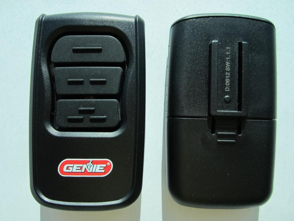
Click to zoom
Application Details
- Equipment Class
- DSC - Part 15 Security/Remote Control Transmitter
- Date of Grant
- Jul 09, 2012
- Application Purpose
- Original Equipment
- Date of Application
- Jul 09, 2012
- Equipment Note
- Hand held or visor mounted wireless door opener
- Frequency Range
- 390.00000000 - 390.00000000
- Country
- United States
Documents & Files
Document Text
Text extracted from the exhibit documents filed with the FCC. Open a document above to read the original.
Users Manual
FIG. 1 POWERHEADS (for various models) 3738450013137384500131 REMOTE BUTTONS LEDs (red/green) NON ROLLING CODE BUTTONS YELLOW LED DEFAULT BUTTON BATTERY DEFAULT9-BIT 9-TRI IC/CD 1 12-BIT - 0 + 1 2 3 4 5 6 7 8 9 10 1 1 12 ECE AD BC CODE SWITCHES REAR COVER INSIDE REAR COVER FIG. 3 FOR HELP OR ANSWERS TO QUESTIONS, CALL 800 354 3643 or visit www.geniecompany.com WARNINGFCC ID: IC: FCC PART 15 COMPANY Circle shows location of Learn Code Button and LED. PRGM SET – + FIG. 2 GenieMaster TM - 0 + 1 2 3 4 5 6 7 8 9 10 11 12 ECE FIG. 1 TETE MOTORISÉE (pour divers modèles) BOUTONS DE LA TÉLÉCOMMANDE Diodes (rouge/ verte) COMMUTATEURS DE CODE FIXES DEL JAUNE BOUTON PAR DÉFAUT PILE DEFAULT9-BIT 9-TRI IC/CD 1 12-BIT - 0 + 1 2 3 4 5 6 7 8 9 10 1 1 12 ECE AD BC COMMUTATEURS DE CODE L’EXTÉRIEUR COUVERCLE ARRIÈRE L’INTÉRIEUR COUVERCLE ARRIÈRE FIG. 3 Pour toute assistance ou réponses à vos questions, appelez le 800-354-3643 ou visitez notre site à l'adresse suivante : www.geniecompany.com WARNINGFCC ID: IC: FCC PART 15 COMPANY PRGM SET – + FIG. 2 GenieMaster TM - 0 + 1 2 3 4 5 6 7 8 9 10 11 12 ECE A. À utiliser avec les ouvre-portes Intellicode® 1— La télécommande Universal est livrée en standard avec le mode de fonctionnement Intellicode® 1. La diode Rouge sur la télécommande qui s'allume chaque fois qu'on appuie sur un bouton signale le mode Intellicode® 1(FIG. 2). Programmez cette télécommande comme n'importe quelle autre télécommande Intellicode® 1 en procédant comme suit : 1. Repérez le bouton de programmation du code ainsi que la diode de l'indicateur de code de programmation sur la tête motorisée de votre ouvre-porte (FIG. 1) (Voir le guide de l'utilisateur). 2. Appuyez puis relâchez le bouton de programmation du code. La diode du code de programmation se met à clignoter rapidement. 3. Appuyez puis relâchez un bouton de la télécommande. (FIG. 2)—La diode du code de programmation reste allumée (cesse de clignoter). 4. Appuyez puis relâchez le même bouton de programmation du code. La diode du code de programmation s'éteint. 5. Appuyez puis relâchez à nouveau le même bouton de programmation du code—L'ouvre-porte se met en marche. REMARQUE: Un bouton de la télécommande doit être a ecté à chaque ouvre-porte. Pour programmer d'autres ouvre-portes, répétez la procédure ci-dessus en utilisant un bouton de télécommande di érent. B. À utiliser avec des ouvre-portes Intellicode® 2— Le bouton ou les boutons sur votre télécommande à utiliser pour faire fonctionner les ouvre-portes Intellicode® 2, doivent être réglés sur le mode de fonctionnement Intellicode® 2. La diode VERTE sur la télécommande qui s'allume chaque fois qu'on appuie sur un bouton signale le mode Intellicode® 2 (FIG. 2). Pour passer en mode Intellicode® 2: 1. Appuyez et maintenez le bouton de la télécommande sélectionné. Une diode ROUGE s'allume et 10 secondes plus tard, une diode VERTE. 2. Relâchez le bouton. 3. Appuyez puis relâchez à nouveau le même bouton DEUX FOIS. Les diodes de la télécommande s'éteignent. 4. Appuyez puis relâchez à nouveau le même bouton. La diode VERTE de la télécommande s'allume lorsqu'on appuie sur ce bouton, signalant que le mode Intellicode® 2 est maintenant activé. Pour programmer la télécommande sur un ouvre-porte: 1. Appuyez sur le bouton PROGRAM/SET (FIG. 1) de la tête motrice de l'ouvre-porte pendant 2 secondes ou jusqu'à ce que la diode ronde soit BLEUE. Une fois le bouton relâché, la diode BLEUE s'éteint et la diode ALLONGÉE s'allume en VIOLET. 2. Appuyez puis relâchez le bouton de la télécommande à a ecter à cet ouvre-porte. 3. Appuyez puis relâchez le même bouton. Après avoir relâché le bouton une deuxième fois, les deux diodes s'éteignent. 4. Appuyez puis relâchez à nouveau le même bouton. L'ouvre-porte se met en marche. . C. À utiliser avec les ouvre-portes ayant une rangée de commutateurs de code (9 à 12 boutons). (Si vous disposez déjà d'une télécommande avec un commutateur de code activé, il su t de faire correspondre les commutateurs de votre nouvelle télécommande GenieMaster™ à ceux de votre ancienne télécommande et de passer ensuite à l'étape 4) (FIG.3) Pour faire fonctionner un opérateur équipé d'un commutateur de code: 1. Ouvrez la lentille de l'éclairage de l'ouvre-porte pour pouvoir accéder à sa rangée de commutateurs de code. Ces commutateurs disposent de 3 positions qui sont +, – et 0. 2. Faites glisser le couvercle arrière de la télécommande (FIG. 3). 3. Dé nissez les positions des commutateurs de code de la télécommande pour qu'ils correspondent à ceux de l'ouvre-porte. (Si vous disposez d'un opérateur à 9 commutateurs, réglez les commutateurs de la télécommande 10, 11 et 12 au centre ou sur 0). 4. Repérez l'étiquette du commutateur xe située à l'intérieur du couvercle arrière (FIG. 3). 5. Appuyez sur le commutateur de code xe B, C ou D (FIG. 3) correspondant à la description du commutateur de code approprié sur l'étiquette. La diode JAUNE près de la pile se met à clignoter. 6. Appuyez et relâchez le bouton de la télécommande à attribuer à cet ouvre-porte. La diode VERTE de la télécommande se met à clignoter pendant environ 2 secondes et s'arrête. 7. Appuyez sur le même bouton pour remettre l'ouvre-porte en marche—La diode ROUGE de la télécommande se met à clignoter lorsqu'on appuie sur le bouton. D. Remplacement de la pile. (Le remplacement de la pile n'a aucune incidence sur la programmation.) 1. Faire glisser la carte de circuit située à l'arrière de la télécommande (FIG. 3). 2. Faites glissez l'ancienne pile vers la partie inférieure de la télécommande et sortez-la. 3. Jetez la vieille pile selon la réglementation en vigueur. 4. Installez la pile neuve (taille 2032) puis placez le couvercle pour refermer. E. Reprogrammation de la télécommande Pour restaurer le mode initial de l'Intellicode® 1 : 1. Faites glisser le couvercle de la carte de circuit (FIG. 3). 2. Appuyez sur le bouton DEFAULT. La diode jaune se met à clignoter. 3. Appuyez sur le bouton de la télécommande à reprogrammer. C'…
Text truncated - open the document above for the full version.
Users Manual
37385500131 FOR HELP OR ANSWERS TO QUESTIONS , CALL 800 929 3667 or visit www.overheaddoor.com PRGM SET – + NETWORK BBU FIG. 1 POWERHEADS (for various models) REMOTE BUTTONS LEDs (red/green) Circle indicates location of Learn Code Button and LED. PRGM SET – + FIG. 2 1 2 3 4 5 6 7 8 9 10 11 12 CODE SWITCH TYPE FRONT FRONT INSIDE LIGHT LENS BOTTOM BOTTOM FRONT 1 2 3 4 5 6 7 8 9 10 11 12 BACK PRIOR TO 1995 AND CODEDODGER® CODEDODGER 2 2010 TO PRESENT CODEDODGER® 1 —1995 TO PRESENT CODE LEARN SET SET OPEN FORCE CLOSECODE LEARNLIMITMANUAL NON ROLLING CODE BUTTONS YELLOW LED DEFAULT BUTTON BATTERY DEFAULT9-BIT 9-TRI IC/CD 1 12-BIT - 0 + 1 2 3 4 5 6 7 8 9 10 1 1 12 ECE AD BC CODE SWITCHES REAR COVER INSIDE REAR COVER FIG. 3 WARNINGFCC ID: IC: FCC PART 15 COMPANY - 0 + 1 2 3 4 5 6 7 8 9 10 11 12 ECE Master TM 37385500131 Master TM A. For use with CodeDodger® 1 Openers— The Universal Remote comes from the factory in the CodeDodger® 1 Operating Mode. The CodeDodger®1 Mode is indicated by a RED LED on the remote whenever a button is pressed (FIG. 2). Program it as you would any CodeDodger® 1 remote using the following steps: 1. Locate the Learn Code Button and Learn Code Indicator LED on your opener’s powerhead (FIG. 1) (See owner’s manual). 2. Press and release the Learn Code Button—the Learn Code LED will blink rapidly. 3. Press and release a Remote Button, (FIG. 2)—the Learn Code LED will stay on (stops blinking). 4. Press and release the same Remote Button again—the Learn Code LED will turn o . 5. Press and release the same Remote Button again—the Door Opener will run. NOTE: Each opener must have its own assigned Remote Button. To program additional openers, repeat the steps above using a di erent Remote Button. B. For use with CodeDodger® 2 Openers— The button or buttons on your remote that you wish to use to operate CodeDodger® 2 openers, must be switched to the CodeDodger® 2 Operating Mode. The CodeDodger® 2 Mode is indicated by a GREEN LED on the remote whenever a button is pressed (FIG. 2). To shift to CodeDodger® 2 mode: 1. Press and hold the chosen Remote Button—A steady RED LED will be illuminated and after 10 seconds—a GREEN LED will also illuminate. 2. Release the button. 3. Press and release that same button again TWICE—the remote’s LEDs will both turn o . 4. Press and release that same button again—the remote’s GREEN LED will light while you press that button – indicating it is now in CodeDodger® 2 mode. To program the remote to an opener: 1. Press and hold the PROGRAM/SET (FIG. 1) button on your opener’s powerhead for 2 seconds or until the round LED turns BLUE. When you release the button the BLUE LED will go out and the LONG LED will turn PURPLE. 2. Press and release the Remote Button you want to assign to that opener. 3. Press and release that same button. After releasing the button the second time, the LEDs will both be o . 4. Press and release that same button again—the Door Opener will run. C. For use with Openers having a row of Code Switches (9 or 12 switches). (If you already have a working “code switch” remote, simply match your new Master™ Remote switches to those on your existing remote and proceed to step 4.)(FIG.3) To operate a Code Switch equipped operator: 1. Open the opener’s light lens in order to gain access to its row of Code Switches. These are 3 position switches (+, – and 0). 2. Slide o the rear cover of the remote (FIG. 3). 3. Set the Code Switches positions in the remote to match those of the switches in the opener. (If you are working with a 9 switch operator, set the remote switches 10, 11 and 12 to the center or “0” position) 4. Locate the non-rolling code button label inside the Rear Cover (FIG. 3): 5. Press the non-rolling code button B, C or D (FIG.3) that matches the appropriate code switch description on the label. The YELLOW LED next to the battery will begin ashing. 6. Press and release the Remote Button you want to assign to that opener—the GREEN LED on the remote will ash for approximately 2 seconds and stop. 7. Pressing the same button again will operate the opener—The RED LED on the remote will ash while the button is pressed. D. Replacing the Battery. (Programming will not be a ected by battery replacement.) 1. Slide the Circuit Board Cover o the back of the remote (FIG. 3). 2. Slide the old battery toward the bottom of the remote and out. 3. Properly discard the old battery. 4. Slide a new (2032 size) battery into position and slide the Cover back on. E. Resetting the Remote To return a Remote Button to its original CodeDodger® 2 mode: 1. Slide the Circuit Board Cover o (FIG. 3). 2. Press the DEFAULT button—the yellow LED will ash. 3. Press the Remote Button you wish to reprogram. Its now CodeDodger® 2 again. FIG. 1 TETE MOTORISÉE (pour divers modèles) BOUTONS DE LA TÉLÉCOMMANDE Diodes (rouge/ verte) COMMUTATEURS DE CODE FIXES DEL JAUNE BOUTON PAR DÉFAUT PILE DEFAULT9-BIT 9-TRI IC/CD 1 12-BIT - 0 + 1 2 3 4 5 6 7 8 9 10 1 1 12 ECE AD BC COMMUTATEURS DE CODE L’EXTÉRIEUR COUVERCLE ARRIÈRE L’INTÉRIEUR COUVERCLE ARRIÈRE FIG. 3 Pour toute assistance ou réponses à vos questions, appelez le 800-275-6187 ou visitez notre site à l'adresse suivante : www.overheaddoor.com WARNINGFCC ID: IC: FCC PART 15 COMPANY PRGM SET – + FIG. 2 - 0 + 1 2 3 4 5 6 7 8 9 10 11 12 ECE A. À utiliser avec les ouvre-portes CodeDodger® 1— La télécommande Universal est livrée en standard avec le mode de fonctionnement CodeDodger® 1. La diode Rouge sur la télécommande qui s'allume chaque fois qu'on appuie sur un bouton signale le mode CodeDodger® 1(FIG. 2). Programmez cette télécommande comme n'importe quelle autre télécommande CodeDodger® 1 en procédant comme suit : 1. Repérez le bouton de programmation du code ainsi que la diode de l'indicateur de code de programmation sur la tête motorisée de votre ouvre-porte (FIG. 1) (Voir le guide de l'utilisateur). 2. Appuyez puis relâchez le bouton de programmation du code. La diode du code de programmation se met à clignoter rap…
Text truncated - open the document above for the full version.
Cover Letter(s)
Date: 05/24/2012 Nemko Canada Inc. 303 River Road Ottawa, Ontario, Canada K1V 1H2 FCC ID: B8Q-315390U Product Name: GenieMaster Remote Model: GM3T and OM3T Request for Confidentiality Pursuant to Sections 0.457 and 0.459 of the commissions’ rules, we hereby request that the following documents be held confidential: Electrical Schematics and Bills of Material Theory of Operation Documentation PCB Assembly and Block Diagram These materials contain trade secrets and proprietary information and are not customarily released to the public. The public disclosure of this information might be harmful to the company and provide unjustified benefits to our competitors. Dated this 24th Day of May 2012 By: Greg Matias Signature Printed Title: Compliance Engineer On behalf of : The Genie Company a Division of Overhead Door Corporation Telephone: 330-763-8150
Cover Letter(s)
DATE : April 16, 2012 Nemko Canada Inc 303 River Road Ottawa, Ontario, Canada K1V 1H2 Attn: Director of Certification FCC ID: B8Q-315390U Authority to Act as Agent FCC On our behalf, I appoint Lina Kwee Nguyen, of Nemko USA, Inc. at 802 N Kealy Avenue, Lewisville TX 75057 to act as our agent in the preparation of this application for equipment certification. I certify that submitted documents properly describe the device or system for which equipment certification is sought. I also certify that each unit manufactured, imported or marketed, as defined in FCC regulations will have affixed to it a label identical to that submitted for approval with this application. In signing this letter, Applicant certifies that neither the applicant nor any party to the application is not subject to a denial of Federal benefits, that include FCC benefits, pursuant to Section 5301 of the Anti-Drug Abuse Act of 1988, 21 U.S.C. § 862 because of a conviction for possession or distribution of a controlled substance. See 47 CFR 1.2002(b) for the definition of a "party" for these purposes. For instances where our authorized agent signs the application for certification on our behalf, I acknowledge that all responsibility for complying with the terms and conditions for certification, as specified by Nemko Canada Inc, still resides with The Genie Company, P.O. Box 67 Mt. Hope, OH 44660. Dated this 16 th Day of April 2012 Agency agreement expiration date: April 15 th 2013 By: Greg Matias Signature Printed Name Title: Compliance Engineer On behalf of : The Genie Company a Division of Overhead Door Corporation Telephone: 330-763-8150
Cover Letter(s)
Date: 04/16/2012 Federal Communications Commission 445 12th Street, SW Washington, DC 20554 FCC: B8Q-315390U To whom it may concern, The following products are electronically and physically identical. The only difference is the branding of the devices. The Genie Company Model: GM3T Overhead Door Corporation Model: OM3T Sincerely, ____ ____Greg Matias__________ Signature Printed Title: ____Compliance Engineer____ On behalf of: ____The Genie Company a Division of Overhead Door Corporation Telephone: __330-763-8150____ Genie Company P. O. Box 67 Mt. Hope, OH 44660 Phone: 800-827-3667 (DOOR) Fax: 330-763-8042 www.geniecompany.com
Test Report
Nemko Test Report: 10217368RUS1rev3 Applicant: Overhead Door TREQ Center, Suite B2170 French Settlement Road Dallas, TX 75212 USA Equipment Under Test: GM3T and OM3T (E.U.T.) FCC ID.: B8Q-315390U IC: 2133A-315390U In Accordance With: FCC Part 15, Subpart C 15.231 and Industry Canada RSS-210, Issue 8 For Low Power Transmitters Operating Periodically In The Band 40.66 - 40.77 MHz And Above 70 MHz Tested By: Nemko USA, Inc. 802 N. Kealy Lewisville, TX 75057-3136 TESTED BY: DATE: 05 March 2012 David Light, Senior Wireless Engineer APPROVED BY: DATE: 6 March 2012 Mike Cantwell Total Number of Pages: 20 Nemko USA, Inc. FCC PART 15, SUBPART C 15.231 and Industry Canada RSS-210, Issue 8 PERIODICALLY OPERATED LOW POWER TRANSMITTERS EQUIPMENT: GM3T and OM3T PROJECT NO.: 10217368RUS1rev3 Page 2 of 20 TABLE OF CONTENTS SECTION 1. SUMMARY OF TEST RESULTS 3 SECTION 2. EQUIPMENT UNDER TEST (E.U.T.) 5 SECTION 3. TRANSMISSION REQUIREMENTS 7 SECTION 4. RADIATED EMISSIONS 9 SECTION 5. OCCUPIED BANDWIDTH 14 SECTION 6. BLOCK DIAGRAMS 17 ANNEX A - RESTRICTED BANDS 19 Nemko USA, Inc. FCC PART 15, SUBPART C 15.231 and Industry Canada RSS-210, Issue 8 PERIODICALLY OPERATED LOW POWER TRANSMITTERS EQUIPMENT: GM3T and OM3T PROJECT NO.: 10217368RUS1rev3 Page 3 of 20 Section 1. Summary of Test Results Manufacturer: Overhead Door Model No.: GM3T and OM3T General: All measurements are traceable to national standards. These tests were conducted on a sample of the equipment for the purpose of demonstrating compliance with Part 15, Subpart C, Paragraph 15.231 and Industry Canada RSS-210. All tests were conducted using measurement procedure ANSI C63.4-2003. Radiated emissions are made on an open area test site. A description of the test facility is on file with the FCC and Industry Canada. New Submission Production Unit Class II Permissive Change Pre-Production Unit THIS TEST REPORT RELATES ONLY TO THE ITEM(S) TESTED. THE FOLLOWING DEVIATIONS FROM, ADDITIONS TO, OR EXCLUSIONS FROM THE TEST SPECIFICATIONS HAVE BEEN MADE. See “ Summary of Test Data”. Nemko USA Inc. authorizes the above named company to reproduce this report provided it is reproduced in its entirety and for use by the company’s employees only. This report must not be used to claim product certification, approval, or endorsement by NVLAP, NIST, or any agency of the Federal Government. Nemko USA, Inc. is a NVLAP accredited laboratory. Any use which a third party makes of this report, or any reliance on or decisions to be made based on it, are the responsibility of such third parties. Nemko USA Inc. accepts no responsibility for damages, if any, suffered by any third party as a result of decisions made or actions based on this report. This report applies only to the items tested. Nemko USA, Inc. FCC PART 15, SUBPART C 15.231 and Industry Canada RSS-210, Issue 8 PERIODICALLY OPERATED LOW POWER TRANSMITTERS EQUIPMENT: GM3T and OM3T PROJECT NO.: 10217368RUS1rev3 Page 4 of 20 Summary Of Test Data Name of Test Paragraph No. Results Transmission Requirements 15.231(a) / A1.1.1 Complies Radiated Emissions 15.231(b) / A1.1 Table A Complies Occupied Bandwidth 15.231(c) / A1.1.3 Complies Frequency Tolerance 15.231(d) / A1.1.4 NA Alternate Field Strength Requirements 15.231(e) / A1.1 Table B NA Powerline Conducted Emissions 15.207 & RSS-Gen 7.2.4 NA Footnotes: 1) The device does not operate between 40.66 to 40.70 MHz 2) The device does not operate at a pre-determined periodic rate. 3) The device is battery powered. Revisions: Rev1 – Added test data for 315 MHz mode. Rev2 – Changed model name. Nemko USA, Inc. FCC PART 15, SUBPART C 15.231 and Industry Canada RSS-210, Issue 8 PERIODICALLY OPERATED LOW POWER TRANSMITTERS EQUIPMENT: GM3T and OM3T PROJECT NO.: 10217368RUS1rev3 Page 5 of 20 Section 2. Equipment Under Test (E.U.T.) General Equipment Information Frequency Range: 315 and 390 MHz Operating Frequency(ies) of Sample: 315 and 390 MHz Type of Emission: OOK Emission Designator: 128KL1D Supply Power Requirement: 3 Vdc (lithium battery) Nemko USA, Inc. FCC PART 15, SUBPART C 15.231 and Industry Canada RSS-210, Issue 8 PERIODICALLY OPERATED LOW POWER TRANSMITTERS EQUIPMENT: GM3T and OM3T PROJECT NO.: 10217368RUS1rev3 Page 6 of 20 Description of E.U.T. Hand held or visor mounted wireless door opener. System Diagram Nemko USA, Inc. FCC PART 15, SUBPART C 15.231 and Industry Canada RSS-210, Issue 8 PERIODICALLY OPERATED LOW POWER TRANSMITTERS EQUIPMENT: GM3T and OM3T PROJECT NO.: 10217368RUS1rev3 Page 7 of 20 Section 3. Transmission Requirements NAME OF TEST: Transmission Requirements PARA. NO.: 15.231(a) / A1.1.1 TESTED BY: David Light DATE: 09 January 2012 Minimum Standard: 15.231(a) Continuous transmissions such as voice, video or data transmissions are not permitted. 15.231(a)(1) A manually operated transmitter shall employ a switch that will automatically deactivate the transmitter within not more than 5 seconds after being released. 15.231(a)(2) A transmitter activated automatically shall cease transmission within 5 seconds of activation. 15.231(a)(3) Periodic transmissions at regular pre- determined intervals are not permitted. However polling or supervisory transmissions to determine system integrity of transmitters used in security or safety applications are allowed if the periodic rate of transmission does not exceed one transmission of not more than one second duration per hour for each transmitter. 15.231(a)(4) Intentional radiators which are employed for radio control purposes during emergencies involving fire, security, and safety of life, when activated to signal an alarm, may operate during the pendency of the alarm. Test Results: Complies. Test Data: Compliance was determined by verification of technical specifications and a functional test on the equipment. Nemko USA, Inc. FCC PART 15, SUBPART C 15.231 and Industry Canada RSS-210, Issue 8 PERIODICALLY OPERATED LOW POWER TRANSMITTERS EQUIPMENT: GM3T and OM3T PROJECT NO.: 10217368RUS1rev3 Page 8 of 20 Rationale…
Text truncated - open the document above for the full version.
Contact Information
Applicant
Mike Whitley(RF Engineer)
Technical Contact
The Genie CompanyGreg Matias
[email protected]330-763-8150
1 Door Drive PO Box 67 · Mt. Hope · United States
Non-Technical Contact
Nemko USA, Inc.Lina Kwee Nguyen
[email protected]469-877-6150
Test Firm
Nemko Dallas, Inc.Mike Cantwell
Technical Specifications
| # | Rule Parts | Frequency Range | Power Output |
|---|---|---|---|
| 2 | 15.231 | 390 MHz - 390 MHz | - |
Other Applications from The Genie Company a Division of Overhead Door Corporation
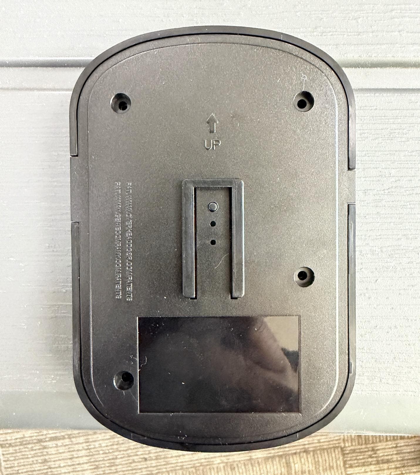
B8QALDCM2
Jun 05, 2026Door COntrol Module
Equipment Class
DSC - Part 15 Security/Remote Control TransmitterB8QALDPS2
May 29, 2026Door Position Sensor
Equipment Class
DTS - Digital Transmission System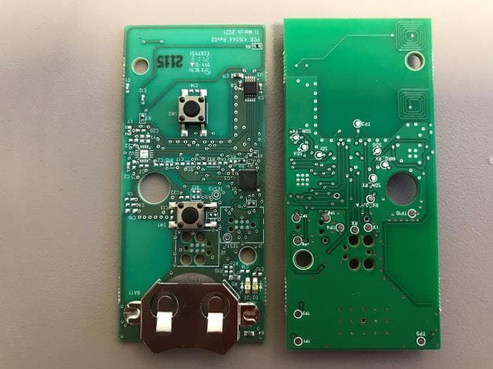
B8QU2
Jul 11, 2021Universal 2 Button Transmitter
Equipment Class
DSC - Part 15 Security/Remote Control Transmitter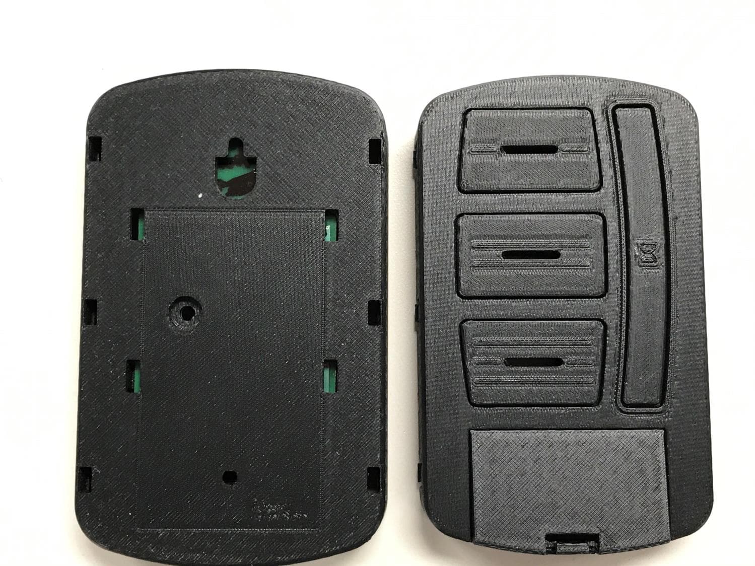
B8QUWWC
Mar 22, 2021Universal Wireless Wall Console
Equipment Class
DSC - Part 15 Security/Remote Control Transmitter
B8Q1BTX
Sep 15, 20201 Button Transmitter
Equipment Class
DSC - Part 15 Security/Remote Control Transmitter