B8QALDPS2Door Position Sensor
The Genie Company a Division of Overhead Door CorporationApplication Details
- Equipment Class
- DTS - Digital Transmission System
- Date of Grant
- May 29, 2026
- Application Purpose
- Original Equipment
- Equipment Note
- Door Position Sensor
- Frequency Range
- 2402.00000000 - 2480.00000000
- Country
- United States
Documents & Files
Document Text
Text extracted from the exhibit documents filed with the FCC. Open a document above to read the original.
Users Manual
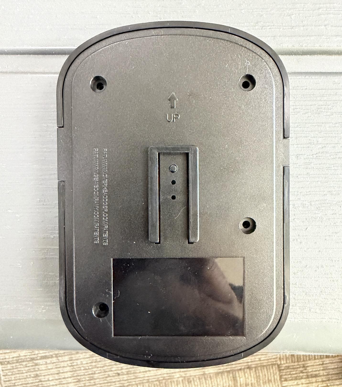
• You will need a ladder, a #2 Phillips head screwdriver, a 3/32 drill bit, and drill. • A light will flash, and a beep will sound as indication that the door is about to move when commanded by the Aladdin Connect or compatible app(s). • These instructions will show the physical installation of the retrofit kit pieces only. All other instructions are defined in the app. KNOW BEFORE YOU BEGIN DOWNLOAD THE APP & CREATE AN ACCOUNT MOUNT & POWER DOOR CONTROL HUB Placement examples 2. Install the Door Control Hub: • If mounting to drywall, use the mounting bracket as a template to mark and drill 2-3/32” pilot holes. Use provided anchors as needed (FIG A). • If mounting to perforated angle at opener location, use nuts, washers and screws provided (FIG B). 3. Slide the Door Control Hub onto its mounting bracket so it snaps into place (FIG C). 4. Plug in the USB-C to the Hub and power cord to the outlet. The Wi-Fi LED on the Hub should light up when powered on (FIG C). 5. Affix the unattended warning placard next to wall control in plain sight to signify that the door can operate remotely. Tacks or staples (not supplied) should be used if the placard does not adhere to the mounting surface (FIG C). Wall Mount Anchors (as needed) MOUNT & POWER DOOR POSITION SENSOR Locate the Door Position Sensor with its mounting bracket and hardware. You will need a ladder to access the top section of your garage door. DO NOT remove the battery pull tab until directed by the app. 1. Standing inside the garage looking out, find the end stile on the far left or right of the TOP PANEL OF THE GARAGE DOOR (FIG G), directly under the top hinge. NOTE: DO NOT mount to unreinforced door panel. 2. Vertically and horizontally center the mounting bracket between the top roller bracket and first hinge. 3. Use the mounting bracket as a template to mark and pre-drill (2) 3/32 holes and use the included self-tapping screws to mount the bracket to top door panel end stile (FIG H). NOTE: DO NOT drill all the way through door. 4. Slide Door Position Sensor down onto mounting bracket until it snaps into place (FIG I). 5. Use the app to continue Wi-Fi setup and complete installation. 42863.03010 1/26 ©2026 The Genie Company One Door Drive, Mt. Hope, OH 44660, USA 1-year warranty, visit www.geniecompany.com for details. Pat. www.geniecompany.com/patents ® For help, contact our Aladdin Connect ® team at 866-599-4995 or visit us at www.geniecompany.com READ AND FOLLOW ALL INSTALLATION INSTRUCTIONS To reduce the risk of severe injury or death to persons: • DO NOT install this product on garage door openers made prior to 1993 without safety sensors. • DO NOT install this product on one piece doors. • Install hub in a location where it can be seen and heard while standing in the door opening with the door in the open position. • This operating system is designed for unattended operation. The door could move unexpectedly. ! WARNING Contents Door Control Hub Door Control Hub Plug & Adapter Door Control Hub Mounting Bracket & Hardware Door Position Sensor, Mounting Bracket & Hardware Warning Placard 112612.0001 WARNING AVERTISSEMENT MOVING DOOR can cause serious injury or death. MOUVEMENT PORTE peut causer des blessures graves ou la mort. STAND CLEAR! Door could close automatically. Do Not stop or stand in doorway SE TENIR À L'ÉCART DE LA PORTE! La porte pourrait se refermer automatiquement. Ne pas arrêter ou debout dans la porte. 1. Scan the QR code to download the Aladdin Connect app and create an account. 2. Press the plus sign on the home screen, then select door. Follow the installation and setup instructions in the app. 1. Locate the Door Control Hub with its mounting bracket and hardware. Select an installation location that meets the following listed criteria: • Can be seen and heard from anywhere inside the garage. • Should be less than 30ft from the garage door opener. • Should be within 5ft of standard 110v AC power outlet. • Should have at least two bars of Wi-Fi signal when a smartphone is placed in the proposed position. If there are not at least two bars in the desired location, try these steps to improve Wi-Fi signal strength: -Make sure that the Wi-Fi router is out in the open (not concealed). -Move the Wi-Fi router closer to the garage. -Purchase a Wi-Fi extender, available at most electronics stores. Locations could be above the opener secured to drywall, fastened to the perforated angle that holds the opener, near the wall console or any other location that meets the above criteria. Perforated Angel Mount 112612.0001 WARNING AVERTISSEMENT MOVING DOOR can cause serious injury or death. MOUVEMENT PORTE peut causer des blessures graves ou la mort. STAND CLEAR! Door could close automatically. Do Not stop or stand in doorway SE TENIR À L'ÉCART DE LA PORTE! La porte pourrait se refermer automatiquement. Ne pas arrêter ou debout dans la porte. FIG AFIG BFIG C Standing inside the garage, looking out, locate the end stiles of the TOP PANEL of the garage door. FIG G FIG H FIG I • Remove and immediately recycle or dispose of used batteries according to local regulations and keep away from children. Do NOT dispose of batteries in household trash or incinerate. • Even used batteries may cause severe injury or death. • Call a local poison control center for treatment information. • Replace only with Type CR2450 3V batteries. • Non-rechargeable batteries are not to be recharged. • Do not force discharge, recharge, disassemble, heat above (manufacturer’s specified temperature rating) or incinerate. Doing so may result in injury due to venting, leakage or explosion resulting in chemical burns. • Ensure the batteries are installed correctly according to polarity (+ and -). • Do not mix old and new batteries, different brands or types of batteries, such as alkaline, carbon-zinc, or rechargeable batteries. • Remove and immediately recycle or dispose of batteries from equipment not used for an extended period of time according to local regula…
Text truncated - open the document above for the full version.
Users Manual
Contact our Aladdin Connect® team for help at 866-599-4995 or visit us at www.geniecompany.com ©2025 The Genie Company One Door Drive, Mt. Hope, OH 44660, USA 1-year warranty, visit www.geniecompany.com for details. Pat. www.geniecompany.com/patents AVERTISSEMENT WARNING 2. Locate the Door Control Hub with its mounting bracket and hardware. Select an installation location that meets the following listed criteria: • Should be seen and heard when garage door from anywhere inside the garage • Should be less than 30ft from the garage door opener • Should be within 5ft of standard 110v AC power outlet • Should have at least 2 bars of Wi-Fi signal when a smartphone is placed in the proposed position. If there are not at least two bars in the desired location, try these steps to improve Wi-Fi signal strength: o Make sure that the Wi-Fi router is out in the open (not concealed) o Move the Wi-Fi router closer to the garage o Purchase a Wi-Fi extender, available at most electronics stores Locations could be above the opener secured to drywall, fastened to the perforated angle that holds the opener, near the wall console or any other location that meets the above criteria. 1. Scan the QR code to download the free Aladdin Connect app and create an account. Follow in-app instructions to complete physical installation and Wi-Fi setup. You may refer to this instruction for physical installation if preferred. 3. Install the Door Control Hub: • If mounting to drywall, use the mounting bracket as a template to mark and drill 2-3/32” pilot holes. Use provided anchors as needed (FIG A). • If mounting to perforated angle at opener location, use nuts, washers and screws provided (FIG B). 4. Slide the Door Control Hub onto its mounting bracket so it snaps into place (FIG C). 5. Plug in the USB-C to the Hub and the power cord to the outlet. The Wi-Fi LED on the Hub should light up when powered on (FIG C). 6. Affix the unattended warning placard next to wall control in plain sight to signify that the door can operate remotely. Tacks or staples (not supplied) should be used if the placard does not adhere to the mounting surface (FIG G). Locate the Door Position Sensor with its mounting bracket and hardware. You will need a ladder to access the top section of your garage door. DO NOT remove the battery pull tab until directed by the app. 6. Standing inside the garage looking out, find the end stile on the far left or right of the TOP PANEL OF THE GARAGE DOOR (FIG G), directly under the top hinge. NOTE: DO NOT mount to unreinforced door panel. 7. Vertically and horizontally center the mounting bracket between the top roller bracket and first hinge. 8. Use the mounting bracket as a template to mark and pre-drill (2) 3/32 holes and use the included self-tapping screws to mount the bracket to top door panel end stile (FIG H). NOTE: DO NOT drill all the way through door. 9. Slide Door Position Sensor down onto mounting bracket until it snaps into place (FIG J). 8. Continue to follow the app instructions to setup your garage door opener brand and pair it to the Door Control Hub. You will need a ladder to access your garage door opener for these steps. ® 112612.0001 WARNING AVERTISSEMENT MOVING DOOR can cause serious injury or death. MOUVEMENT PORTE peut causer des blessures graves ou la mort. STAND CLEAR! Door could close automatically. Do Not stop or stand in doorway SE TENIR À L'ÉCART DE LA PORTE! La porte pourrait se refermer automatiquement. Ne pas arrêter ou debout dans la porte. Wall Mount Anchors (as needed) Perforated Angle Mount QR CODE FPO Contents Door Control Hub Door Control Hub Plug & Adapter Door Control Hub Mounting Bracket & Hardware Door Position Sensor, Mounting Bracket & Hardware Warning Placard 112612.0001 WARNING AVERTISSEMENT MOVING DOOR can cause serious injury or death. MOUVEMENT PORTE peut causer des blessures graves ou la mort. STAND CLEAR! Door could close automatically. Do Not stop or stand in doorway SE TENIR À L'ÉCART DE LA PORTE! La porte pourrait se refermer automatiquement. Ne pas arrêter ou debout dans la porte. FIG C FIG A FIG B FIG D Standing inside the garage, looking out, locate the end stiles of the TOP PANEL of the garage door. FIG G FIG H FIG J TO REDUCE THE RISK OF SEVERE INJURY OR DEATH, READ AND FOLLOW INSTRUCTIONS: 1. TBD waiting for Greg KNOW BEFORE YOU BEGIN: • A light will flash, and a beep will sound as indication that the door is about to move when commanded by the Aladdin Connect® or other compatible app(s). • These instructions will show the physical installation of the retrofit kit pieces only. All other instructions are defined in the app. DOWNLOAD THE APP MOUNT & POWER DOOR POSITION SENSOR MOUNT & POWER DOOR CONTROL HUB 112612.0001 WARNING AVERTISSEMENT MOVING DOOR can cause serious injury or death. MOUVEMENT PORTE peut causer des blessures graves ou la mort. STAND CLEAR! Door could close automatically. Do Not stop or stand in doorway SE TENIR À L'ÉCART DE LA PORTE! La porte pourrait se refermer automatiquement. Ne pas arrêter ou debout dans la porte. 112612.0001 WARNING AVERTISSEMENT MOVING DOOR can cause serious injury or death. MOUVEMENT PORTE peut causer des blessures graves ou la mort. STAND CLEAR! Door could close automatically. Do Not stop or stand in doorway SE TENIR À L'ÉCART DE LA PORTE! La porte pourrait se refermer automatiquement. Ne pas arrêter ou debout dans la porte. FOLLOW THE APP TO PAIR THE DOOR CONTROL HUB TO THE GARAGE DOOR OPENER
ID Label/Location Info
Genie Company P. O. Box 67 Mt. Hope, OH 44660 Phone: 800-827-3667 (DOOR) Fax: 330-763-8042 www.geniecompany.com Genie Company P. O. Box 67 Mt. Hope, OH 44660 Phone: 800-827-3667 (DOOR) Fax: 330-763-8042 www.geniecompany.com
ID Label/Location Info
Genie Company P. O. Box 67 Mt. Hope, OH 44660 Phone: 800-827-3667 (DOOR) Fax: 330-763-8042 www.geniecompany.com FCC labels on the DPS battery cover. FCC label goes here. FCC label
ID Label/Location Info
LICENSE OR AUTHORIZATION TO USE IT ANGULAR = ±1 02/05/2026 AH MATERIAL 43139 APPROVED SIZE TOLERANCES: SYMBOL ' WRITTEN CONSENT OF OVERHEAD DOOR INSPECTION STANDARDS. APPROVALS DISCLOSED TO ANYONE WITHOUT PRIOR NOTES: (UNLESS OTHERWISE SPECIFIED) D C B A AB C D 1 2 3 4 5 6 7 8 8 THIRD ANGLE PROJECTION REMOTE GENIE 2/6/26 PLOTTED: 4/2/26 2/5/26 7 TD B ENG F.20.041B-(FORM REV A) 43139 1 TO QUALITY DESIGN 4 FOR ANY PURPOSE WITHOUT SPECIFIC A SUBSIDIARY OF OVERHEAD DRAWING OR INFORMATION IS INTENDED CORPORATION. DISCLOSURE OF ANY UNLESS OTHERWISE SPECIFIED .X = ±.1 SCALE 4:1 MT HOPE, OHIO CORPORATION. SPEC, LABEL, FCC/IC, DPS WRITTEN CONSENT OF OVERHEAD DOOR .XX = ±.01 6 3 .XXX = ±.005 DRAWN DIMS CIRCLED WITH NOT TO AND SHALL NOT OPERATE AS A ALL GEOMETRY GOVERNED BY 3D CAD DATABASE: .003 CHECKED DESCRIPTION DATE DWG NO. HOLES: INCHES INTERPRET DIMS & TOLS SHEET 1 OF 1 MBW 2 MIL MYLAR W/PSA ALL DIMS ARE IN PER ASME Y14.5M DOOR CORPORATION DO NOT SCALE FINISH 2 5 ' ARE CRITICAL FEATURES & MUST MEET APPLICABLE IN-PROCESS THE DRAWINGS AND ALL OTHER INFORMATION CONTAINED HEREIN ARE THE CONFIDENTIAL PROPRIETARY PROPERTY OF OVERHEAD DOOR CORPORATION, INCLUDING ITS AFFILIATED SUBSIDIARIES AND AFFILIATES. THIS DRAWING INFORMATION, IN WHOLE OR IN PART, MAY NOT BE COPIED IN ANY MANNER OR < Ø.251 = .003 Ø.251-Ø.500 = .003 > Ø.500 = P/N 43139A REVISIONS GCO REV DESCRIPTION DATE APPROVAL 03010 - ORIGINAL ISSUE 03010-1 A REVISE LABEL SPEC TO INCLUDE CORRECT COUNTRY & INCREASED LABEL SIZE 3/27/26 TD 03010-2 B REMOVED LABEL FINISH,UPDATED MFG DATE :DEFOND TO MATAMOROS, CHANGED PATENT INFORMATION 4/2/26 TD LABEL BACKGROUND TO BE WHITE. 1. PRINTING TO BE BLACK. 2. ALL FONTS TO BE ARIAL NARROW, 0.045" TALL UNLESS OTHERWISE NOTED. 3. MFG DATE: 4. YYYY = YEAR 1. MM = MONTH 2. dd = DAY 3. M = MATAMOROS 4. S = SHIFT NUMBER 5. a. 1 = LINE 1, SHIFT 1 b. 2 = LINE 1, SHIFT 2 c. 3 = LINE 2, SHIFT 1 d. 4 = LINE 2, SHIFT 2 e. 5 = LINE 3, SHIFT 1 f. ... AND SO ON XXXX = UNIT NUMBER 6.LABEL BACKGROUND TO BE WHITE. 1. PRINTING TO BE BLACK. 2. ALL FONTS TO BE ARIAL NARROW, 0.045" TALL UNLESS OTHERWISE NOTED. 3. MFG DATE: 4. YYYY = YEAR 1. MM = MONTH 2. dd = DAY 3. M = MATAMOROS 4. S = SHIFT NUMBER 5. a. 1 = LINE 1, SHIFT 1 b. 2 = LINE 1, SHIFT 2 c. 3 = LINE 2, SHIFT 1 d. 4 = LINE 2, SHIFT 2 e. 5 = LINE 3, SHIFT 1 f. ... AND SO ON XXXX = UNIT NUMBER 6. FONT HEIGHT 0.070" FONT HEIGHT 0.038" 1.000 .750 R.13 REF. SCALE 1:1
RF Exposure Info
Engineering Test Report No. 2502548-02 Report Date April 14, 2026 Manufacturer Name Genie Company Manufacturer Address Overhead Door Co. TREQ Center 2170 French Settlement Rd Dallas, TX 75212 Product Name Brand/Model No. Door Position Sensor ALDPS2 Date Received 1/20/2026 Assessment Dates 1/20/2026 – 1/22/2026 Specifications FCC "Code of Federal Regulations" Title 47 Part 1, Subpart I FCC 447498 D04 Interim General RF Exposure Guidance v01 RSS-102 Issue 6 EN 62311 EN 62479 RPS S-1 Test Facility Elite Electronic Engineering, Inc. 1516 Centre Circle, Downers Grove, IL 60515 Signature Tested by Jack Gallet Signature Approved by Raymond J. Klouda, Re gistered Professional Engineer of Illinois – 44894 PO Number 979347 This report is for your exclusive use. Any copying or replication of this report to or for any other person or entity, or use of our name or trademark, is permitted only with our prior written permission. This report sets forth our findings solely with respect to the test samples identified herein. The results set forth in this report are not indicative or representative of the quality or characteristics of the lot from which a test sample was taken or any similar or identical product unless specifically and expressly noted. Our report includes the results thereof based upon the information that you provided to us. You have 60 days from date of issuance of this report to notify us of any material error or omission caused by our negligence, provided, however, that such notice shall be in writing and shall specifically address the issue you wish to raise. A failure to raise such issue within the prescribed time shall constitute your unqualified acceptance of the completeness of this report, the tests conducted and the correctness of the report contents. This report shall not be reproduced, except in full, without the written approval of Elite Electronic Engineering Inc. The data presented in this test report pertains to the EUT on the test dates specified. Additionaly, the assessment results presented in this test report are only valid at the separation distance(s) stated in section 8. The results in this test report shall not be used to claim product exemption or comformity at separation distances not covered in this report. Any electrical or mechanical modifications made to the EUT subsequent to the specified test date will serve to invalidate the data and void this certification. This report must not be used to claim product certification, approval, or endorsement by A2LA, NIST, or any agency of the Federal Government. Engineering Test Report No. 2502548-02 This report shall not be reproduced, except in full, without the written approval of Elite Electronic Engineering Inc. Page 2 of 28 Table of Contents 1. Report Revision History ........................................................................................................................... 3 2. Introduction .............................................................................................................................................. 4 3. Subject of Investigation ............................................................................................................................ 4 4. Standards and Requirements .................................................................................................................. 4 5. Sample Calculations ................................................................................................................................ 5 6. Photographs of EUT ................................................................................................................................ 6 7. Limits and Requirements ......................................................................................................................... 9 7.1. Requirements mandated by the FCC ...................................................................................................... 9 7.2. Requirements mandated by Innovation, Science and Economic Development Canada ...................... 11 7.3. Requirements mandated by the European Union and outlined in EN 62311 ........................................ 12 7.4. Requirements mandated by Australia/New Zealand and outlined in RPS S-1 ...................................... 13 8. Assessment Results .............................................................................................................................. 14 8.1. RF Exposure Evaluation Pertinent to the Requirements of the FCC of a Single RF Source ................ 14 8.2. RF Exposure Evaluation Relevant to the Requirements of the ISED of a Single RF Source ............... 14 8.3. RF Exposure Evaluation Relevant to the Requirements of the EU of a Single RF Source ................... 16 8.4. RF Exposure Evaluation Relevant to the Requirements of the Australia/New Zealand of a Single RF Source 16 9. Statement of Compliance ....................................................................................................................... 17 10. Scope of Accreditation ........................................................................................................................... 18 Engineering Test Report No. 2502548-02 Page 3 of 28 1. Report Revision History Revision Date Description – 15 APR 2026 Initial Release of Engineering Test Report No. 2502548-02 Engineering Test Report No. 2502548-02 Page 4 of 28 2. Introduction The FCC, Innovation, Science and Economic Development Canada, European Union and Australia/New Zealand publish standards regarding the evaluation of the RF Exposure hazard of radio communications devices. An evaluation has been performed on the Genie Company Door Position Sensor, Model No. ALDPS2 pursuant to the relevant requirements. 3. Subject of Investigation This document presents the demonstration of RF Exposure compliance on two (2) Door Position Sensors (hereinafter referred to as the Equipment under Test (EUT)). The …
Text truncated - open the document above for the full version.
Test Report
Genie Company P. O. Box 67 Mt. Hope, OH 44660 Phone: 800-827-3667 (DOOR) Fax: 330-763-8042 www.geniecompany.com Antenna Gain Information Genie Company P. O. Box 67 Mt. Hope, OH 44660 Phone: 800-827-3667 (DOOR) Fax: 330-763-8042 www.geniecompany.com
Test Report
Engineering Test Report No. 2502548-01 Rev. A Report Date January 26, 2026 Manufacturer Name Genie Company Manufacturer Address Overhead Door Co. TREQ Center 2170 French Settlement Rd Dallas, TX 75212 Equipment Under Test Model No. Door Position Sensor ALDPS2 Date Received 1/20/2026 Test Dates 1/20/2026 – 1/22/2026 Specifications FCC "Code of Federal Regulations" Title 47 Part 15, Subpart C, Section 15.247 Innovation, Science, and Economic Development Canada, RSS-GEN Innovation, Science, and Economic Development Canada, RSS-247 Test Facility Elite Electronic Engineering, Inc. 1516 Centre Circle, Downers Grove, IL 60515 FCC Reg. Number: 269750 IC Reg. Number: 2987A CAB Identifier: US0107 Signature Tested by Jack Gallet Signature Approved by Raymond J. Klouda, Re gistered Professional Engineer of Illinois – 44894 PO Number 979347 This report is for your exclusive use. Any copying or replication of this report to or for any other person or entity, or use of our name or trademark, is permitted only with our prior written permission. This report sets forth our findings solely with respect to the test samples identified herein. The results set forth in this report are not indicative or representative of the quality or characteristics of the lot from which a test sample was taken or any similar or identical product unless specifically and expressly noted. Our report includes all of the tests requested by you and the results thereof based upon the information that you provided to us. You have 60 days from date of issuance of this report to notify us of any material error or omission caused by our negligence, provided, however, that such notice shall be in writing and shall specifically address the issue you wish to raise. A failure to raise such issue within the prescribed time shall constitute your unqualified acceptance of the completeness of this report, the tests conducted and the correctness of the report contents. This report shall not be reproduced, except in full, without the written approval of Elite Electronic Engineering Inc. Elite Electronic Engineering Incorporated certifies that the information contained in this report was obtained under conditions which meet or exceed those specified in the FCC "Code of Federal Regulations" Title 47 Part 15, Subpart C, Section 15.247 and Innovation, Science, and Economic Development Canada, RSS-247 test specifications. The data presented in this test report pertains to the EUT on the test dates specified. Any electrical or mechanical modifications made to the EUT subsequent to the specified test date will serve to invalidate the data and void this certification. This report must not be used to claim product certification, approval, or endorsement by A2LA, NIST, or any agency of the Federal Government. Engineering Test Report No. 2502548-01 Rev. A This report shall not be reproduced, except in full, without the written approval of Elite Electronic Engineering Inc. Page 2 of 63 Table of Contents 1. Report Revision History ........................................................................................................................... 3 2. Introduction .............................................................................................................................................. 4 2.1. Scope of Tests ......................................................................................................................................... 4 2.2. Purpose .................................................................................................................................................... 4 2.3. Identification of the EUT ........................................................................................................................... 4 3. Power Input .............................................................................................................................................. 5 4. Grounding ................................................................................................................................................ 5 5. Support Equipment .................................................................................................................................. 5 6. Interconnect Leads .................................................................................................................................. 5 7. Modifications Made to the EUT ................................................................................................................ 5 8. Modes of Operation ................................................................................................................................. 5 9. Test Specifications ................................................................................................................................... 5 10. Test Plan .................................................................................................................................................. 6 11. Deviation, Additions to, or Exclusions from Test Specifications .............................................................. 6 12. Laboratory Conditions .............................................................................................................................. 6 13. Summary .................................................................................................................................................. 6 14. Sample Calculations ................................................................................................................................ 6 15. Statement of Conformity .......................................................................................................................... 7 16. Certification .............................................................................................................................................. 7 17. Photographs of EUT .......................…
Text truncated - open the document above for the full version.
Test Report
Engineering Test Report No. 2502548-01 Rev. A Page 52 of 63 Test Details Manufacturer Genie Company Equipment Under Test Door Position Sensor Model No. ALDPS2 Serial No. A1 Mode BLE High Frequency Tested 2480MHz Result PSD = -9.423dBm Notes None BLE High Power Spectral Density DUT Frequency (MHZ) Frequency (MHz) PSD (dBm) Limit Max (dBm) 2480.00 MHz 2479.907035 -9.423 8.0 Engineering Test Report No. 2502548-01 Rev. A Page 53 of 63 28. Scope of Accreditation Engineering Test Report No. 2502548-01 Rev. A Page 54 of 63 Engineering Test Report No. 2502548-01 Rev. A Page 55 of 63 Engineering Test Report No. 2502548-01 Rev. A Page 56 of 63 Engineering Test Report No. 2502548-01 Rev. A Page 57 of 63 Engineering Test Report No. 2502548-01 Rev. A Page 58 of 63 Engineering Test Report No. 2502548-01 Rev. A Page 59 of 63 Engineering Test Report No. 2502548-01 Rev. A Page 60 of 63 Engineering Test Report No. 2502548-01 Rev. A Page 61 of 63 Engineering Test Report No. 2502548-01 Rev. A Page 62 of 63 Engineering Test Report No. 2502548-01 Rev. A Page 63 of 63
Contact Information
Applicant
Mike Whitley(RF Engineer)
[email protected]Fax: 330-763-8011
Test Firm
Elite Electronic Engineering Inc.Kevin Halpin
[email protected]Fax: 630-495-9785
Technical Specifications
| # | Rule Parts | Frequency Range | Power Output |
|---|---|---|---|
| 1 | 15C | 2.40 GHz - 2.48 GHz | 1.30 mW |
Other Applications from The Genie Company a Division of Overhead Door Corporation
B8QALDCM2
Jun 05, 2026Door COntrol Module
Equipment Class
DSC - Part 15 Security/Remote Control Transmitter
B8QU2
Jul 11, 2021Universal 2 Button Transmitter
Equipment Class
DSC - Part 15 Security/Remote Control Transmitter
B8QUWWC
Mar 22, 2021Universal Wireless Wall Console
Equipment Class
DSC - Part 15 Security/Remote Control Transmitter
B8Q1BTX
Sep 15, 20201 Button Transmitter
Equipment Class
DSC - Part 15 Security/Remote Control Transmitter
B8Q-UKEP
Mar 12, 2020Universal Keypad Transmitter
Equipment Class
DSC - Part 15 Security/Remote Control Transmitter