B8QU2Universal 2 Button Transmitter
The Genie Company a Division of Overhead Door Corporation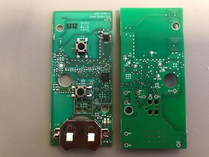
Click to zoom
Application Details
- Equipment Class
- DSC - Part 15 Security/Remote Control Transmitter
- Date of Grant
- Jul 11, 2021
- Application Purpose
- Original Equipment
- Date of Application
- Jul 11, 2021
- Equipment Note
- Universal 2 Button Transmitter
- Frequency Range
- 433.92000000 - 433.92000000
- Country
- United States
Documents & Files
Document Text
Text extracted from the exhibit documents filed with the FCC. Open a document above to read the original.
Users Manual
XXXXX.00XXX - PR4, 02/2021 UNIVERSAL 2-BUTTON REMOTE INSTRUCTIONS WARNING ! MOVING DOOR CAN CAUSE SERIOUS INJURY OR DEATH. • DO NOT install transmitter unless the door operator’s safety device works as required by the door operator’s manual. • Wall Console must be mounted in sight of door, at least 5 feet above floor and clear of moving door parts. • Keep people clear of opening while door is moving. • DO NOT allow children to play with the transmitter or door operator. If safety reverse does not work properly: • Close door then disconnect opener using the manual release handle. • DO NOT use transmitter or door operator. • Refer to Door and Door Opener Owner’s Manuals before attempting any repairs. NOT FOR USE WITH ANY GARAGE DOOR OPENER MANUFACTURED PRIOR TO 1993. SAFETY BEAMS (PHOTOCELLS) MUST BE IN PLACE AND OPERATIONAL. AVERTISSEMENT UNE PORTE EN MOUVEMENT PEUT CAUSER DE GRAVES BLESSURES, VOIRE LA MORT. • N’installez PAS le transmetteur à moins que l’appareil de sécurité du dispositif de fermeture de porte ne fonctionne conformément au manuel du dispositif de fermeture de porte. La console murale doit être montée à la vue de la porte, à au moins 5 pieds au-dessus du sol et il ne doit y avoir aucune pièce de porte en mouvement à proximité. • Éloignez les gens de l’ouverture lorsque la porte est en mouvement. • NE permettez PAS aux enfants de jouer avec le transmetteur ou le dispositif de fermeture de porte. • Si l’inversion de sécurité ne fonctionne pas correctement : • Fermez la porte, puis déconnectez le dispositif d’ouverture à l’aide de la poignée de dégagement manuel. • N’utilisez PAS le transmetteur ni le dispositif de fermeture de porte. • Référez-vous aux manuels du propriétaire de la porte et de l’ouvre-porte avant de tenter toute réparation. ! THINGS TO KNOW BEFORE STARTING: • During programming, the garage door opener may operate. Ensure that the garage door opening is clear of personnel or any obstructions. • Do not to press the LEARN button for longer than the noted 2-3 seconds as it could cause your existing, operational remotes and keypads to no longer work. • All buttons are factory set to Genie Intellicode® 1. Below are the brands and specifications that this remote is compatible with. Find the ID# in Chart A below that references your specific opener specification. You will need this number during programming. Refer to STEP 1 to find the type and/or LEARN/ PROGRAM button. NOTE: During programming, the garage door opener will operate. Ensure that the garage door opening is clear of personnel or any obstructions. Chart A Genie® and Intellicode® are registered trademarks of The Genie Company. All other listed names and trademarks are the property of their respective owners. STEP 1 - Find Specifications & Learn Button 1. Locate the brand and opener/receiver specifications for your device by consulting the label on the opener/receiver, the instruction manual, the current remote controls for the opener, or the original manufacturer of the opener/receiver. 2. Find the LEARN/PROG button on your device - shape, color or name of this button could vary by brand. For garage door openers, be sure to check under the light covers. For commercial or gate openers, this button may be on the circuit board of the opener. In some cases, this button could also be on an external receiver that is mounted on or nearby the product. Consult the devices manual if needed. Activation Tab: Pull tab to activate the remote. STEP 2 - Activate Remote/Button Layout & LED LED - The LED will light with each button press and will also light in response to button presses during different programming modes. PRGM SET RADIO SIGNAL LEARN CODE CODE LEARN Gate Receivers EXAMPLES: *For Marantec® openers, reference operator manual to program remotes to the operator head. FCC Part 15.21 Statement: Changes or modifications not expressly approved by the party responsible for compliance could void the user’s authority to operate the equipment. FCC / IC Statement: This device complies with FCC Part 15 and Industry Canada licence-exempt RSS standard(s). Operation is subject to the following two conditions: (1) this device may not cause harmful interference, and (2) this device must accept any interference received, including interference that may cause undesired operation of the device. Programming Assistance: If the opener does not activate after the steps shown, repeat steps or contact Customer Care by website chat (www.geniecompany.com) or by phone at: 1-800-354-3643 for programming assistance. You may also scan this QR code for additional information and links. For Patent Information: www.geniecompany.com/patents, ©2021, The Genie Company STEP 3 - Programming Remote IMPORTANT: For ID#4 Chamberlain®/LiftMaster®/Craftsman® Yellow Learn Button - move immediately to the proper section below. For all other ID#s, proceed to LEARN METHOD section. LEARN METHOD Review Chart A to find your specifications and available programming options. Each button can be programmed individually to operate up to 2 different brands of garage door openers and gate receivers. 1. Remove activation tab from inside battery compartment. 2. Find and remember the required number of button presses (ID#) in the LEARN METHOD column next to your brands/specification in Chart A. REMEMBER: For ID#4 Chamberlain®/LiftMaster®/Craftsman® Yellow Learn Button ONLY - Move immediately to instructions below. For all other ID#s, proceed to step 3. 3. On remote, press and hold down BOTH buttons at the same time – as soon as the RED LED begins flashing, immediately release both buttons (@ 5 seconds). 4. On remote, press button of your choice the required number of times from CHART A. 5. When presses are complete, simply wait until the GREEN LED blinks and then goes out. 6. On opener, press LEARN/PROGRAM button for 2-3 seconds and then release. 7. Press and release button you just programmed once every 2 seconds until the garage door opener operates. 8. Test the butto…
Text truncated - open the document above for the full version.
Users Manual
41711.00670, 02/2021 UNIVERSAL 2-BUTTON REMOTE INSTRUCTIONS WARNING ! MOVING DOOR CAN CAUSE SERIOUS INJURY OR DEATH. • DO NOT install transmitter unless the door operator’s safety device works as required by the door operator’s manual. • Wall Console must be mounted in sight of door, at least 5 feet above floor and clear of moving door parts. • Keep people clear of opening while door is moving. • DO NOT allow children to play with the transmitter or door operator. If safety reverse does not work properly: • Close door then disconnect opener using the manual release handle. • DO NOT use transmitter or door operator. • Refer to Door and Door Opener Owner’s Manuals before attempting any repairs. NOT FOR USE WITH ANY GARAGE DOOR OPENER MANUFACTURED PRIOR TO 1993. SAFETY BEAMS (PHOTOCELLS) MUST BE IN PLACE AND OPERATIONAL. AVERTISSEMENT UNE PORTE EN MOUVEMENT PEUT CAUSER DE GRAVES BLESSURES, VOIRE LA MORT. • N’installez PAS le transmetteur à moins que l’appareil de sécurité du dispositif de fermeture de porte ne fonctionne conformément au manuel du dispositif de fermeture de porte. La console murale doit être montée à la vue de la porte, à au moins 5 pieds au-dessus du sol et il ne doit y avoir aucune pièce de porte en mouvement à proximité. • Éloignez les gens de l’ouverture lorsque la porte est en mouvement. • NE permettez PAS aux enfants de jouer avec le transmetteur ou le dispositif de fermeture de porte. • Si l’inversion de sécurité ne fonctionne pas correctement : • Fermez la porte, puis déconnectez le dispositif d’ouverture à l’aide de la poignée de dégagement manuel. • N’utilisez PAS le transmetteur ni le dispositif de fermeture de porte. • Référez-vous aux manuels du propriétaire de la porte et de l’ouvre-porte avant de tenter toute réparation. ! THINGS TO KNOW BEFORE STARTING: • During programming, the garage door opener may operate. Ensure that the garage door opening is clear of personnel or any obstructions. • Do not to press the LEARN button for longer than the noted 2-3 seconds as it could cause your existing, operational remotes and keypads to no longer work. • All buttons are factory set to Genie Intellicode® 1. Below are the brands and specifications that this remote is compatible with. Find the ID# in Chart A below that references your specific opener specification. You will need this number during programming. Refer to STEP 1 to find the type and/or LEARN/ PROGRAM button. NOTE: During programming, the garage door opener will operate. Ensure that the garage door opening is clear of personnel or any obstructions. Chart A Genie® and Intellicode® are registered trademarks of The Genie Company. All other listed names and trademarks are the property of their respective owners. STEP 1 - Find Specifications & Learn Button 1. Locate the brand and opener/receiver specifications for your device by consulting the label on the opener/receiver, the instruction manual, the current remote controls for the opener, or the original manufacturer of the opener/receiver. 2. Find the LEARN/PROG button on your device - shape, color or name of this button could vary by brand. For garage door openers, be sure to check under the light covers. For commercial or gate openers, this button may be on the circuit board of the opener. In some cases, this button could also be on an external receiver that is mounted on or nearby the product. Consult the devices manual if needed. Activation Tab: Pull tab to activate the remote. STEP 2 - Activate Remote/Button Layout & LED LED - The LED will light with each button press and will also light in response to button presses during different programming modes. PRGM SET RADIO SIGNAL LEARN CODE CODE LEARN Gate Receivers EXAMPLES: *For Marantec® openers, reference operator manual to program remotes to the operator head. FCC Part 15.21 Statement: Changes or modifications not expressly approved by the party responsible for compliance could void the user’s authority to operate the equipment. FCC / IC Statement: This device complies with FCC Part 15 and Industry Canada licence-exempt RSS standard(s). Operation is subject to the following two conditions: (1) this device may not cause harmful interference, and (2) this device must accept any interference received, including interference that may cause undesired operation of the device. Programming Assistance: If the opener does not activate after the steps shown, repeat steps or contact Customer Care by website chat (www.geniecompany.com) or by phone at: 1-800-354-3643 for programming assistance. You may also scan this QR code for additional information and links. For Patent Information: www.geniecompany.com/patents, ©2021, The Genie Company STEP 3 - Programming Remote IMPORTANT: For ID#4 Chamberlain®/LiftMaster®/Craftsman® Yellow Learn Button - move immediately to the proper section below. For all other ID#s, proceed to LEARN METHOD section. LEARN METHOD Review Chart A to find your specifications and available programming options. Each button can be programmed individually to operate up to 2 different brands of garage door openers and gate receivers. 1. Remove activation tab from inside battery compartment. 2. Find and remember the required number of button presses (ID#) in the LEARN METHOD column next to your brands/specification in Chart A. REMEMBER: For ID#4 Chamberlain®/LiftMaster®/Craftsman® Yellow Learn Button ONLY - Move immediately to instructions below. For all other ID#s, proceed to step 3. 3. On remote, press and hold down BOTH buttons at the same time – as soon as the RED LED begins flashing, immediately release both buttons (@ 5 seconds). 4. On remote, press button of your choice the required number of times from CHART A. 5. When presses are complete, simply WAIT until the GREEN LED blinks and then goes out. 6. On opener, press LEARN/PROGRAM button for 2-3 seconds and then release. 7. Press and release button you just programmed once every 2 seconds until the garage door opener operates. 8. Test the button - pr…
Text truncated - open the document above for the full version.
Cover Letter(s)
Agency agreement expiration date: July 22, 2022 By: David Hui Signature Printed Name Title: Sr. RF Engineer On behalf of : The Genie Company a Division of Overhead Door Corporation Telephone: 214-579-6325 Genie Company P. O. Box 67 Mt. Hope, OH 44660 Phone: 800-827-3667 (DOOR) Fax: 330-763-8042 www.geniecompany.com Dated this 10 th Day of March 2021 Electronic Engineering, Inc., still resides with The Genie Company, P.O. Box 67 Mt. Hope, OH 44660. that all responsibility for complying with the terms and conditions for certification, as specified by Elite For instances where our authorized agent signs the application for certification on our behalf, I acknowledge regulations will have affixed to it a label identical to that submitted for approval with this application. sought. I also certify that each unit manufactured, imported or marketed, as defined in Industry Canada’s certify that submitted documents properly describe the device or system for which equipment certification is Grove, Illinois 60515, to act as our agent in the preparation of this application for equipment certification. I On our behalf, I appoint Richard King, of Elite Electronic Engineering, Inc.., 1516 Centre Circle, Downers Authority to Act as Agent FCC IC ID: B8QU2 Attn: Director of Certification Downers Grove, Illinois 60515 1516 Centre Circle Elite Electronic Engineering, Inc.
Cover Letter(s)
Elite Electronic Engineering, Inc. 1516 Centre Circle Downers Grove, Illinois 60515-1082 FCC ID: B8QU2 Product Name: Universal 2 Button Transmitter Model: ACSCTG-UNV2, OU2T-P Request for Confidentiality Pursuant to Sections 0.457 and 0.459 of the commissions’ rules, we hereby request that the following documents be held confidential: • Electrical Schematics, Layout Drawings, and Bill of Materials • Theory of Operation Documentation • PCB Assembly and Block Diagram • Internal Pictures These materials contain trade secrets and proprietary information and are not customarily released to the public. The public disclosure of this information might be harmful to the company and provide unjustified benefits to our competitors. Dated this 10th Day of March 2021 By: David Hui Signature Printed Title: Sr. RF Engineer On behalf of : The Genie Company a Division of Overhead Door Corporation Telephone: 214 579-6325 Genie Company P. O. Box 67 Mt. Hope, OH 44660 Phone: 800-827-3667 (DOOR) Fax: 330-763-8042 www.geniecompany.com
ID Label/Location Info
LABEL,FCC/IC SEE NOTE #1 ALL DIMS ARE IN WRITTEN CONSENT OF OVERHEAD DOOR .XX = ±.01 .003 CHECKED NOTES: (UNLESS OTHERWISE SPECIFIED) D C B A AB C D 1 2 3 4 5 6 7 8 8 7 65 4 3 2 1 THIRD ANGLE PROJECTION ENG F.20.041B-(FORM REV A) B 41677 HOLES: PER ASME Y14.5M DO NOT SCALE MBW SEE NOTE #2 DIMS AND SPECIFICATIONS FOR ANY PURPOSE WITHOUT SPECIFIC 1/4/2021 .X = ±.1 MATERIAL UNLESS OTHERWISE SPECIFIED APPROVALS STANDARDS. DISCLOSED TO ANYONE WITHOUT PRIOR CORPORATION. SCALE 6:1 ' ARE CRITICAL TO SHEET 1 OF 1 A SUBSIDIARY OF OVERHEAD PLOTTED: 1/4/21 INCHES .XXX = ±.005 INTERPRET DIMS & TOLS DOOR CORPORATION 41667 APPROVED SIZE TOLERANCES: ' WRITTEN CONSENT OF OVERHEAD DOOR IN-PROCESS INSPECTION CIRCLED WITH SYMBOL NOT TO AND SHALL NOT OPERATE AS A ALL GEOMETRY GOVERNED BY 3D CAD DATABASE: CORPORATION. DIS CLOSURE OF ANY & MUST MEET APPLICABLE DRAWING OR INFORMATION IS INTENDED QUALITY DESIGN FEATURES LICENSE OR AUTHORI ZATION TO USE IT ANGULAR = ±1 DESCRIPTION DATE DWG NO. FINISH MT. HOPE, OHIO DRAWN THE DRAWINGS AND ALL OTHER INFORMATION CONTA INED HEREIN ARE THE CONFIDENTIAL PROPRIETARY PROPERTY OF OVERHEAD DOOR CORPORATION, INCLUDING ITS AFFILIATED SUBSIDIARIES AND AFFILIATES. THIS DRAWING INFORMATION, IN WHOLE OR IN PART, MAY NOT BE COPIED IN ANY MANNER OR < Ø.251 = .003 Ø.251-Ø.500 = .003 > Ø.500 = MODEL NUMBER FCC ID DATA COMPANY NAMEIC DATA P/N 41677B R.030 MODEL NUMBER FCC ID DATA COMPANY NAMEIC DATA .145 ORANGE BACKGROUND 1.000 WHITE BACKGROUND .375 REVISIONS GCO REV DESCRIPTION DATE APPROVAL -01 RELEASE FOR QUOTE 1/5/2021 P/N 41677A BLACK GRAPHICS AND TYPE ON 2 MIL MYLAR WITH 1. PRESSURE SENSITIVE PERMANENT ADHESIVE FOR USE ON ABS PLASTIC, 1 MIL CLEAR MYLAR OVERLAY.CLEAN, COLOR PER ANSI Z535.1. 2.
Test Report
Page 1 of 9 Class 1 Permissive Change Measurements Report Date April 30, 2021 Manufacturer Name Genie Manufacturer Address 2501 S State Hwy 121 Ste 200 Lewisville, TX 75067 Model No. U2 Test Dates April 30, 2021 Specifications FCC "Code of Federal Regulations" Title 47 Part 15, Subpart C, Section 15.231(b) Innovation, Science, and Economic Development Canada, RSS-210 Innovation, Science, and Economic Development Canada, RSS-GEN Test Facility Elite Electronic Engineering, Inc. 1516 Centre Circle, Downers Grove, IL 60515 Tested by Javier Cardenas This report is for your exclusive use. Any copying or replication of this report to or for any other person or entity, or use of our name or trademark, is permitted only with our prior written permission. This report sets forth our findings solely with respect to the test samples identified herein. The results set forth in this report are not indicative or representative of the quality or characteristics of the lot from which a test sample was taken or any similar or identical product unless specifically and expressly noted. Our report includes all of the tests requested by you and the results thereof based upon the information that you provided to us. You have 60 days from date of issuance of this report to notify us of any material error or omission caused by our negligence, provided, however, that such notice shall be in writing and shall specifically address the issue you wish to raise. A failure to raise such issue within the prescribed time shall constitute your unqualified acceptance of the completeness of this report, the tests conducted and the correctness of the report contents. This report shall not be reproduced, except in full, without the written approval of Elite Electronic Engineering Inc. Elite Electronic Engineering Incorporated certifies that the information contained in this report was obtained under conditions which meet or exceed those specified in the FCC "Code of Federal Regulations" Title 47 Part 15, Subpart C, Section 15.231 and Innovation, Science, and Economic Development Canada, RSS-210 and RSS-Gen test specification(s). The data presented in this test report pertains to the EUT on the test date(s) specified. Any electrical or mechanical modifications made to the EUT subsequent to the specified test date will serve to invalidate the data and void this certification. This report must not be used to claim product certification, approval, or endorsement by A2LA, NIST, or any agency of the Federal Government. Page 2 of 9 1. I n t r o d u c t i o n 1.1. Scope of Tests This document presents the limited spurious emissions measurements that were performed on the Genie Universal 2 Button Transmitter (hereinafter referred to as the Equipment Under Test (EUT)). The EUT was manufactured and submitted for testing by Genie located in Lewisville, TX. 1.2. Purpose The measurements were performed to determine if the EUT meets the Class I Permissive Change requirements of the FCC "Code of Federal Regulations" Title 47, Part 15, Subpart C, Sections 15.231(b). The following modifications have been made to the original equipment: - A change of resistor supplier The measurements were also performed to determine if the EUT meets the Class I Permissive Change requirements of the Industry Canada Radio Standards Specification RSS-Gen and Industry Canada Radio Standards Specification RSS-210 for Transmitters. The following modifications have been made to the original equipment: - A change of resistor supplier Testing was performed in accordance with ANSI C63.10-2013. 1.3. Identification of the EUT The EUTs was/were identified as follows: EUT Identification Product Description Universal 2 Button Transmitter Model/Part No. U2 Serial No. NA Band of Operation 303 – 433.92MHz The EUT listed above was used throughout the test series. Page 3 of 9 2. P h o t o g r a p h s o f E U T Page 4 of 9 3. B l o c k D i a g r a m o f T e s t S e t u p A n e c h o i c F e r r i t e C h a m b e r D U T N o n - C o n d u c t i v e T a b l e 3 m e t e r s S p e c t r u m A n a l y z e r C o m p u t e r M o n i t o r M a s t / T u r n - T a b l e C o n t r o l S h i e l d e d E n c l o s u r e R e c e i v e A n t e n n a R a d i a t e d M e a s u r e m e n t s T e s t S e t u p Page 5 of 9 4. E q u i p m e n t L i s t Eq ID Equipment Description Manufacturer Model No. Serial No. Frequency Range Cal Date Due Date CDZ4 LAB WORKSTATION ELITE LWS-10 WINDOWS 10 CNR NTA3 BILOG ANTENNA TESEQ 6112D 32853 25-1000MHz 10/20/2020 10/20/2021 RBG2 EMI ANALYZER ROHDE & SCHWARZ ESW44 101591 2HZ-44GHZ 3/11/2021 3/11/2022 WKA1 SOFTWARE, UNIVERSAL RCV EMI ELITE UNIV_RCV_EMI 1 --- I/O N/A: Not Applicable I/O: Initial Only CNR: Calibration Not Required NOTE 1: For the purpose of this test, the equipment was calibrated over the specified frequency range, pulse rate, or modulation prior to the test or monitored by a calibrated instrument. Page 6 of 9 5. S p u r i o u s R a d i a t e d E m i s s i o n s Test Information Manufacturer Genie Product Universal 2 Button Transmitter Model U2 Serial No NA Mode Continuous Tx Test Date April 30, 2021 Test Setup Details Setup Format Tabletop Height of Support NA Type of Test Site Semi-Anechoic Chamber Test site used Room 21 Notes None Requirements The EUT must comply with the requirements of FCC "Code of Federal Regulations Title 47", Part 15, Subpart C, Section 15.205 et seq. as well as the requirements of the RSS-GEN specification Section 8.10. Carrier Frequency (MHz) Field Strength of Carrier (μV/m) Field Strength of Spurious Emissions (μV/m) 40.66-40.70 70-130 130-174 174-260 260-470 Above 470 2250 1250 1250 to 3750* 3750 3750 to 12500* 12500 225 125 125 to 375* 375 375 to 1250* 1250 *Linear interpolations Page 7 of 9 Test Setup for Spurious Radiated Emissions, 30-1000MHz – Antenna Polarization Horizontal Test Setup for Spurious Radiated Emissions, 30-1000MHz – Antenna Polarization Vertical Page 8 of 9 Test Details Manufacturer Genie Model U2 S/N…
Text truncated - open the document above for the full version.
Test Report
Engineering Test Report No. 2100035-01 Rev. A Report Date February 25, 2021 Manufacturer Name Genie Manufacturer Address 2501 S State Hwy 121 Ste 200 Lewisville, TX 75067 Model No. U2 ISED HVIN: ACSCTG-UNV2 ; OUT-P ISED PMN: ACSCTG-UNV2 ; OUT-P Date Received February 22, 2021 Test Dates February 22 - 24, 2021 Specifications FCC "Code of Federal Regulations" Title 47 Part 15, Subpart C, Section 15.231 (b) Innovation, Science, and Economic Development Canada, RSS-210 Innovation, Science, and Economic Development Canada, RSS-GEN Test Facility Elite Electronic Engineering, Inc. 1516 Centre Circle, Downers Grove, IL 60515 FCC Reg. Number: 269750 IC Reg. Number: 2987A CAB Identifier: US0107 Signature Tested by Javier Cardenas Tylar Jozefczyk Signature Approved by Raymond J. Klouda, Registered Professional Engineer of Illinois – 44894 PO Number 940215 This report is for your exclusive use. Any copying or replication of this report to or for any other person or entity, or use of our name or trademark, is permitted only with our prior written permission. This report sets forth our findings solely with respect to the test samples identified herein. The results set forth in this report are not indicative or representative of the quality or characteristics of the lot from which a test sample was taken or any similar or identical product unless specifically and expressly noted. Our report includes all of the tests requested by you and the results thereof based upon the information that you provided to us. You have 60 days from date of issuance of this report to notify us of any material error or omission caused by our negligence, provided, however, that such notice shall be in writing and shall specifically address the issue you wish to raise. A failure to raise such issue within the prescribed time shall constitute your unqualified acceptance of the completeness of this report, the tests conducted and the correctness of the report contents. This report shall not be reproduced, except in full, without the written approval of Elite Electronic Engineering Inc. Elite Electronic Engineering Incorporated certifies that the information contained in this report was obtained under conditions which meet or exceed those specified in the FCC "Code of Federal Regulations" Title 47 Part 15, Subpart C, Section 15.231 and Innovation, Science, and Economic Development Canada, RSS-210 and RSS-Gen test specification(s). The data presented in this test report pertains to the EUT on the test dates specified. Any electrical or mechanical modifications made to the EUT subsequent to the specified test date will serve to invalidate the data and void this certification. This report must not be used to claim product certification, approval, or endorsement by A2LA, NIST, or any agency of the Federal Government. Engineering Test Report No. 2100035-01 Rev. A This report shall not be reproduced, except in full, without the written approval of Elite Electronic Engineering Inc. Page 2 of 129 Table of Contents 1. Report Revision History ............................................................................................................................ 3 2. Introduction ............................................................................................................................................... 4 2.1. Scope of Tests .......................................................................................................................................... 4 2.2. Purpose ..................................................................................................................................................... 4 2.3. Identification of the EUT ............................................................................................................................ 4 3. Power Input ............................................................................................................................................... 4 4. Grounding ................................................................................................................................................. 4 5. Support Equipment ................................................................................................................................... 4 6. Interconnect Leads .................................................................................................................................... 4 7. Modifications Made to the EUT ................................................................................................................. 4 8. Modes of Operation ................................................................................................................................... 5 9. Test Specifications .................................................................................................................................... 5 10. Test Plan ................................................................................................................................................... 5 11. Deviation, Additions to, or Exclusions from Test Specifications ............................................................... 5 12. Laboratory Conditions ............................................................................................................................... 6 13. Summary ................................................................................................................................................... 6 14. Sample Calculations ................................................................................................................................. 6 15. Statement of Conformity ........................................................................................................................... 6 16. Certification ...........................................................................................................................................…
Text truncated - open the document above for the full version.
Test Report
Engineering Test Report No. 2100035-01 Rev. A Page 43 of 129 Test Details Manufacturer Genie Model No. U2 Serial No. NA Test FCC §15.231, RSS-210 Duty Cycle Mode Pulsed Tx Carrier Frequency 315MHz (Marantec) Notes Duty Cycle Calculation: 11 × 1.53ms = 16.83ms 12 × 0.75ms = 9ms 16.83 + 9 = 25.83 D.C = 20log(25.83/100) = -11.75dB DUTY CYCLE Engineering Test Report No. 2100035-01 Rev. A Page 44 of 129 Test Details Manufacturer Genie Model No. U2 Serial No. NA Test FCC §15.231, RSS-210 Duty Cycle Mode Pulsed Tx Carrier Frequency 318MHz Notes Pulse = 1.0ms DUTY CYCLE – PULSE Engineering Test Report No. 2100035-01 Rev. A Page 45 of 129 Test Details Manufacturer Genie Model No. U2 Serial No. NA Test FCC §15.231, RSS-210 Duty Cycle Mode Pulsed Tx Carrier Frequency 318MHz Notes Duty Cycle Calculation: 17 × 1.0ms = 17ms D.C = 20log(17/100) = -15.39dB DUTY CYCLE Engineering Test Report No. 2100035-01 Rev. A Page 46 of 129 Test Details Manufacturer Genie Model No. U2 Serial No. NA Test FCC §15.231, RSS-210 Duty Cycle Mode Pulsed Tx Carrier Frequency 372.5MHz (Wayne Dalton) Notes Wide Pulse = 400μs = 0.4ms DUTY CYCLE – WIDE PULSE Engineering Test Report No. 2100035-01 Rev. A Page 47 of 129 Test Details Manufacturer Genie Model No. U2 Serial No. NA Test FCC §15.231, RSS-210 Duty Cycle Mode Pulsed Tx Carrier Frequency 372.5MHz (Wayne Dalton) Notes Narrow Pulse = 200μs = 0.2ms DUTY CYCLE – NARROW PULSE Engineering Test Report No. 2100035-01 Rev. A Page 48 of 129 Test Details Manufacturer Genie Model No. U2 Serial No. NA Test FCC §15.231, RSS-210 Duty Cycle Mode Pulsed Tx Carrier Frequency 372.5MHz (Wayne Dalton) Notes Duty Cycle Calculation: 41 × 0.4ms = 16.4ms 38 × 0.2ms = 7.6ms 16.4 + 7.6 = 24 D.C = 20log(24/100) = -12.39dB DUTY CYCLE Engineering Test Report No. 2100035-01 Rev. A Page 49 of 129 Test Details Manufacturer Genie Model No. U2 Serial No.…
Text truncated - open the document above for the full version.
Contact Information
Applicant
Mike Whitley(RF Engineer)
Test Firm
Elite Electronic Engineering Inc.Kevin Halpin
Technical Specifications
| # | Rule Parts | Frequency Range | Power Output |
|---|---|---|---|
| 7 | 15.231 | 433.92 MHz - 433.92 MHz | - |
Other Applications from The Genie Company a Division of Overhead Door Corporation
B8QALDCM2
Jun 05, 2026Door COntrol Module
Equipment Class
DSC - Part 15 Security/Remote Control TransmitterB8QALDPS2
May 29, 2026Door Position Sensor
Equipment Class
DTS - Digital Transmission System
B8QUWWC
Mar 22, 2021Universal Wireless Wall Console
Equipment Class
DSC - Part 15 Security/Remote Control Transmitter
B8Q1BTX
Sep 15, 20201 Button Transmitter
Equipment Class
DSC - Part 15 Security/Remote Control Transmitter
B8Q-UKEP
Mar 12, 2020Universal Keypad Transmitter
Equipment Class
DSC - Part 15 Security/Remote Control Transmitter