B8Q-UKEPUniversal Keypad Transmitter
The Genie Company a Division of Overhead Door Corporation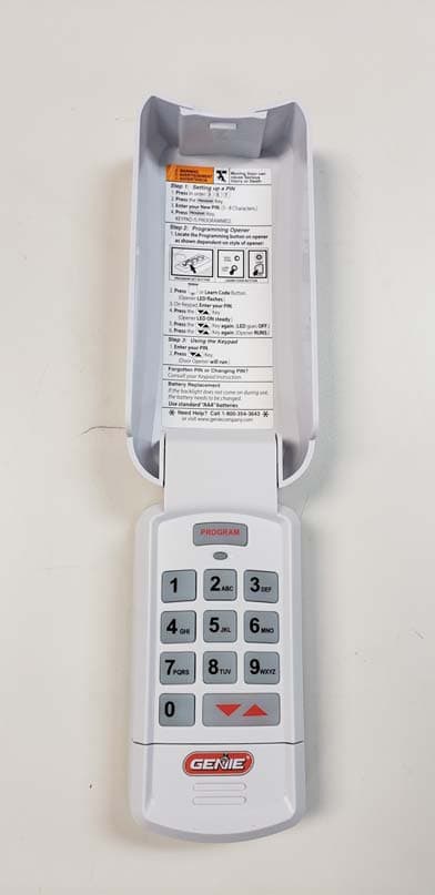
Click to zoom
Application Details
- Equipment Class
- DSC - Part 15 Security/Remote Control Transmitter
- Date of Grant
- Mar 12, 2020
- Application Purpose
- Original Equipment
- Date of Application
- Mar 12, 2020
- Equipment Note
- Universal Keypad Transmitter
- Frequency Range
- 433.92000000 - 433.92000000
- Country
- United States
Documents & Files
Document Text
Text extracted from the exhibit documents filed with the FCC. Open a document above to read the original.
Users Manual
What do fixed code dip switches look like and how do I convert them to button presses on my new universal remote? If the opener has a group of 9 switches with 3 positions per switch (TRINARY): • Switch in the UP position = Press button 1 • Switch in the MIDDLE position = Press button 2 • Switch in the DOWN position = Press button 4 In this example, the button presses would be: If the opener has a group of 9-12 switches with 2 positions per switch (BINARY): + - 123456789101112 STEP 1: Each shaded box below represents a DIP switch position. In these boxes, write in the number 1, 2 or 4 as it corresponds to the UP, MIDDLE or DOWN switch position you see on the remote, opener head or receiver. Convert the 9 switch code: In this example, the button presses would be: • Switch in the UP position = Press button 1 • Switch in the DOWN position = Press button 4 4 1 1 11 1 1 144 4 4 + 0 - 123456789 44111 1 1 22 1234504392, 11/2019 Universal Wireless Keypad Instructions It is recommended to complete programming before mounting keypad Keypad Up/Down Key (enter) Program Key LED LED O LED On LED Flashing Keypad O Keypad OnKeypad Flashing Keypad LED’s Successful EntriesFailed Entries SAVE THESE INSTRUCTIONS FOR FUTURE USE WARNING ! MOVING DOOR CAN CAUSE SERIOUS INJURY OR DEATH. • DO NOT install transmitter (keypad) unless the door operator’s safety device works as required by the door operator’s manual. • Wall Console must be mounted in sight of door, at least 5 feet above floor and clear of moving door parts. • Keep people clear of opening while door is moving. • DO NOT allow children to play with the transmitter or door operator. If safety reverse does not work properly: • Close door then disconnect opener using the manual release handle. • DO NOT use transmitter or door operator. • Refer to Door and Door Opener Owner’s Manuals before attempting any repairs. AVERTISSEMENT ! DÉMÉNAGEMENT PORTE PEUT CAUSER DES BLESSURES GRAVES OU LA MORT. • NE PAS installer le transmetteur (clavier) à moins que le dispositif de sécurité de l’opérateur de porte ne fonctionne comme l’exige le manuel d’utilisation de la porte. • Console murale doit être monté en vue de la porte d’au moins 5 pieds au-dessus-de-chaussée et claire des pièces mobiles de la porte. • Garder les personnes clair de l’ouverture lorsque la porte est en mouvement. • Ne pas laisser les enfants jouer le premier match à distance ou la porte. Si la sécurité inverse ne fonctionne pas correctement: • Fermer la porte, puis débranchez moteur à l’aide de la poignée de déverrouillage manuel. • Ne pas utiliser d’ouverture à distance ou la porte. • Reportez-vous à la porte et ouvre-porte de propriétaires manuels avant de tenter toute réparation. Keypad LED will flash and beep each time a key is pressed and entry is accepted. Keypad LED and PROGRAM key will flash slowly and number pad back light will remain on for 15 seconds indicating a successful program or valid PIN has been entered. Keypad LED, PROGRAM key and number pad back light will flash rapidly indicating a problem with programming or an invalid PIN entry. • Press the 7 & 9 keys together 3 times to start over. Keypad Overview Activate keypad by opening battery compartment and pull protective tab. Reinstall compartment door to begin programming. TAB Scan this code with a QR code reader app on a smart device to view a video of these instructions or visit www.geniecompany.com IDBRAND-TYPEFREQ- MHz TYPEINSTR Group DESCRIPTION 1Genie Intellicode 1315,390Rolling1Genie Intellicode and OHD Mfg from 1995 to present 2Chamberlain (Purple) 315Rolling1Chamberlain, Sears Craftsman, LiftMaster, Master Mechanic, and Do It GDO mfg from 2005 to present (purple button) 3Chamberlain (Orange/Red) 390Rolling1Chamberlain, Sears Craftsman, LiftMaster, Master Mechanic, and Do It GDO mfg from 1997-2004 (orange/red button) 4Chamberlain (Yellow) 390Rolling1Chamberlain, Sears Craftsman, and LiftMaster GDO mfg from 2011 to present (yellow button) 5Chamberlain (Green) 390Rolling1Chamberlain, Sears Craftsman, LiftMaster, Master Mechanic, and Do It GDO mfg from 1993-1996 (green button) 6Genie Intellicode 2315,390Rolling1Genie Intellicode and OHD Mfg from 2011-2012 <what else?> 7Sommer310Rolling1<need details> 8Linear318Fixed- Learn 1Linear GDO mfg from 1997 to present 9Wayne Dalton372.5Rolling1Wayne Dalton GDO mfg from 1999 to present 10Ryobi372.5Rolling1Ryobi GOD mfg from 2016 to present <correct?> 11Guardian303Fixed- Learn 1Guardian and Xtreme GDO mfg from 199x to present <dates? Want others listed, like Boss, Decko, etc?> 12Marantec315Fixed- Learn 1Marantec GDO mfg from 199x to present <dates?> 13FAAC433.92Rolling1 14FUTURE reserve 15FUTURE reserve1 16FUTURE reserve1 17FUTURE reserve1 18FUTURE reserve1 19FUTURE reserve1 20FUTURE reserve1 21Genie - 12 switch binary 390Fixed-Dip212 DIP switch Genie GDO 22Genie - 9 switch binary 390Fixed-Dip29 DIP switch Genie GDO 23Stanley - 10 switch binary 310Fixed-Dip210 switch Stanley and Moore-O-Matic GDO 24FUTURE reserve 25FUTURE reserve Find the model of the garage door opener(s) that this keypad will be operating from the chart below. Mark down the pertinent information in the section below this chart. BOX A: Opener ID - DOOR #1: __________________ Opener ID - DOOR #2: __________________ Opener ID - DOOR #3: __________________ BOX B: Fixed Code Switch ID - DOOR #1: __ - __ - __ - __ Fixed Code Switch ID - DOOR #2: __ - __ - __ - __ Fixed Code Switch ID - DOOR #3: __ - __ - __ - __ FCC Part 15.21 Statement: Changes or modifications not expressly approved by the party responsible for compliance could void the user’s authority to operate the equipment. FCC / IC Statement: This device complies with FCC Part 15 and Industry Canada licence-exempt RSS standard(s). Operation is subject to the following two conditions: (1) this device may not cause harmful interference, and (2) this device must accept any interference received, including interference that may cause undesired operation of the device. …
Text truncated - open the document above for the full version.
Cover Letter(s)
Elite Electronic Engineering, Inc. 1516 Centre Circle Downers Grove, Illinois 60515-1082 FCC ID: B8Q UKEP Product Name: Universal Keypad Model: GUK-BX, GUK-R, OUK-BX Request for Confidentiality Pursuant to Sections 0.457 and 0.459 of the commissions’ rules, we hereby request that the following documents be held confidential: Electrical Schematics, Layout Drawings, and Bills of Materials Theory of Operation Documentation / Technical Description PCB Assembly and Block Diagram These materials contain trade secrets and proprietary information and are not customarily released to the public. The public disclosure of this information might be harmful to the company and provide unjustified benefits to our competitors. Dated this 15th Day of October 2019 By: Mike Whitey Signature Printed Title: Sr. RF Engineer On behalf of : The Genie Company a Division of Overhead Door Corporation Telephone: 830-660-0800 Genie Company P. O. Box 67 Mt. Hope, OH 44660 Phone: 800-827-3667 (DOOR) Fax: 330-763-8042 www.geniecompany.com
External Photos
UKEPFront View UKEPBottomView Models: Genie Pro = GUK-BXGenie Retail = GUK-ROHD Pro = OUK-BXFCC ID: B8Q UKEP IC ID: 2133A-UKEP
ID Label/Location Info
WRITTEN CONSENT OF OVERHEAD DOOR ALL DIMS ARE IN .003 CHECKED APPROVALS DRU NOTES: (UNLESS OTHERWISE SPECIFIED) D C B A AB C D 1 2 3 4 5 6 7 8 8 7 B 5 4 6 3 2 1 1/9/20 .XX = ±.01 MATERIAL DO NOT SCALE A SUBSIDIARY OF OVERHEAD ENG F.20.041B-(FORM REV A) 41214 J.W. PLOTTED: 1/30/20 PER ASME Y14.5M DISCLOSED TO ANYONE WITHOUT PRIOR SEE NOTES KEYLESS ENTRY PAD (UKEP) HOLES: MM .XXX = ±.005 1/3/20 ' ARE CRITICAL TO SCALE 8:1 CORPORATION. ANGULAR = ±1 - APPROVED MT. HOPE, OHIO P/N 41214B DATE DRAWNFINISH ' INTERPRET DIMS & TOLS 41214 DOOR CORPORATION - SIZE TOLERANCES: CIRCLED WITH SYMBOL WRITTEN CONSENT OF OVERHEAD DOOR IN-PROCESS INSPECTION CORPORATION. DISCLOSURE OF ANY NOT TO AND SHALL NOT OPERATE AS A ALL GEOMETRY GOVERNED BY 3D CAD DATABASE: RSM & MUST MEET APPLICABLE THIRD ANGLE PROJECTION DRAWING OR INFORMATION IS INTENDED LICENSE OR AUTHORIZATION TO USE IT QUALITY DESIGN FEATURES DESCRIPTION DWG NO. CLEAN 10/03/19 UNLESS OTHERWISE SPECIFIED DIMS AND SPECIFICATIONS LABEL, FCC/IC, UNIVERSAL FOR ANY PURPOSE WITHOUT SPECIFIC .X = ±.1 SHEET 1 OF 1 STANDARDS. THE DRAWINGS AND ALL OTHER INFORMATION CONTAINED HEREIN ARE THE CONFIDENTIAL PROPRIETARY PROPERTY OF OVERHEAD DOOR CORPORATION, INCLUDING ITS AFFILIATED SUBSIDIARIES AND AFFILIATES. THIS DRAWING INFORMATION, IN WHOLE OR IN PART, MAY NOT BE COPIED IN ANY MANNER OR < Ø.251 = .003 Ø.251-Ø.500 = .003 > Ø.500 = P/N 41214A REVISIONS ER/GCO REV DESCRIPTION DATE APPROVAL 504392 - ORIGINAL ISSUE 00135 A CHANGED FCC ID FROM "B8Q UKEP" TO "B8Q-UKEP" 1/30/20 MLS BLACK GRAPHICS AND TYPE ON 2 MIL MYLAR WITH 1. PRESSURE SENSITIVE PERMANENT ADHESIVE FOR USE ON ABS PLASTIC, 1 MIL CLEAR MYLAR OVERLAY.COLOR PER ANSI Z535.1. 2 2 ORANGE BACKGROUND WHITE BACKGROUND 3.76 9.53 25.40 4X R0.76 WHITE BACKGROUND
Internal Photos
UKEPInsidePCB Top View UKEPInside PCB BottomView UKEPPCBTop View UKEPPCBBottomView
Test Report
Engineering Test Report No. 1903902-01 Measurement of RF Emissions from a UKEP Universal Keypad Transmitter For Genie Company One Door Drive Mount Hope, OH 44660 P.O. Number 4900037120 Date Tested October 21, 2019 through October 24, 2019 Test Personnel Mark E. Longinotti Test Specification FCC "Code of Federal Regulations” Title 47 Part15, Subpart C ISED RSS-GEN ISED RSS-210 Test Report By: Mark E. Longinotti EMC Engineer Requested By: Mike Whitley Genie Company Approved By: Raymond J. Klouda Registered Professional Engineer of Illinois - 44894 Engineering Test Report No. 1903902-01 TABLE OF CONTENTS PARAGRAPH DESCRIPTION OF CONTENTS PAGE NO. THIS REPORT SHALL NOT BE REPRODUCED, EXCEPT IN FULL, WITHOUT THE WRITTEN APPROVAL OF ELITE ELECTRONIC ENGINEERING INCORPORATED. Page 2 of 95 1. Introduction ................................................................................................................................................... 5 1.1. Scope of Tests ..................................................................................................................................... 5 1.2. Purpose ............................................................................................................................................... 5 1.3. Deviations, Additions and Exclusions .................................................................................................. 5 1.4. EMC Laboratory Identification ............................................................................................................. 5 1.5. Laboratory Conditions.......................................................................................................................... 5 2. Applicable Documents .................................................................................................................................. 5 3. EUT Setup and Operation ............................................................................................................................ 6 3.1. General Description ............................................................................................................................. 6 3.1.1. Power Input ................................................................................................................................. 6 3.1.2. Peripheral Equipment ................................................................................................................. 6 3.1.3. Signal Input/Output Leads .......................................................................................................... 6 3.1.4. Grounding ................................................................................................................................... 6 3.2. Software ............................................................................................................................................... 6 3.3. Operational Mode ................................................................................................................................ 6 3.4. EUT Modifications ................................................................................................................................ 7 4. Test Facility and Test Instrumentation ......................................................................................................... 7 4.1. Shielded Enclosure .............................................................................................................................. 7 4.2. Test Instrumentation ............................................................................................................................ 7 4.3. Calibration Traceability ........................................................................................................................ 7 4.4. Measurement Uncertainty ................................................................................................................... 7 5. Test Procedures ........................................................................................................................................... 7 5.1. Powerline Conducted Emissions ......................................................................................................... 7 5.1.1. Requirements .............................................................................................................................. 7 5.2. Periodic Operation Measurements ...................................................................................................... 7 5.2.1. Requirements .............................................................................................................................. 7 5.2.2. Procedures .................................................................................................................................. 8 5.2.3. Results ........................................................................................................................................ 8 5.3. Duty Cycle Factor Measurements ....................................................................................................... 8 5.3.1. Procedures .................................................................................................................................. 8 5.3.2. Results ........................................................................................................................................ 8 5.4. Radiated Measurements ..................................................................................................................... 8 5.4.1. Requirements .............................................................................................................................. 8 5.4.2. Procedures .................................................................................................................................. 9 5.4.3. Results ....................................................…
Text truncated - open the document above for the full version.
Test Setup Photos
Engineering Test Report No. 1903902-01 Page 15 of 95 Figure 3 Test Setup for Radiated Emissions, 30MHz to 1GHz – Horizontal Polarization Test Setup for Radiated Emissions, 30MHz to 1GHz – Vertical Polarization Engineering Test Report No. 1903902-01 Page 16 of 95 Figure 4 Test Setup for Radiated Emissions, Above 1GHz – Horizontal Polarization Test Setup for Radiated Emissions, Above 1GHz – Vertical Polarization
Contact Information
Applicant
Mike Whitley(RF Engineer)
Test Firm
Elite Electronic Engineering Inc.Kevin Halpin
Technical Specifications
| # | Rule Parts | Frequency Range | Power Output |
|---|---|---|---|
| 7 | 15.231 | 433.92 MHz - 433.92 MHz | - |
Other Applications from The Genie Company a Division of Overhead Door Corporation
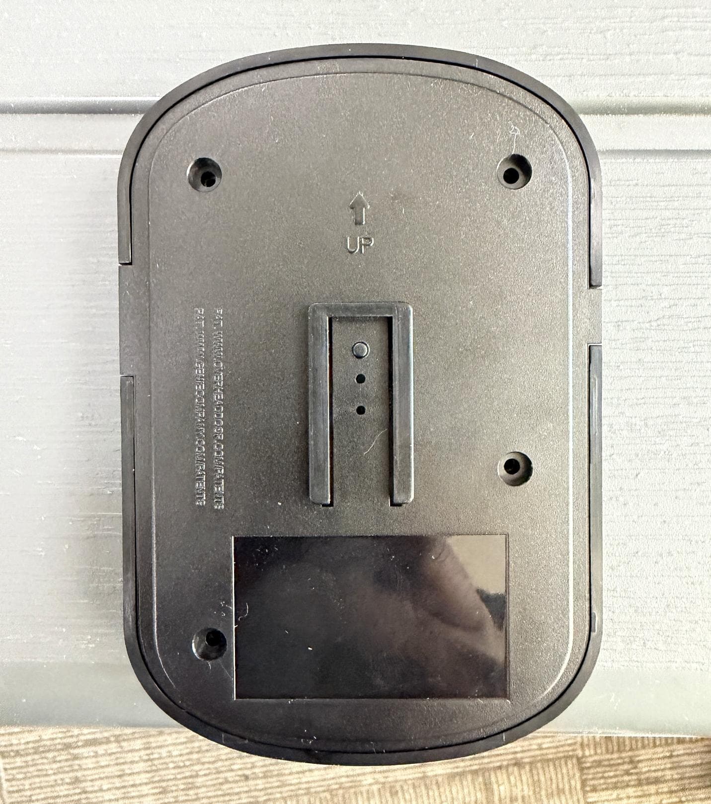
B8QALDCM2
Jun 05, 2026Door COntrol Module
Equipment Class
DSC - Part 15 Security/Remote Control TransmitterB8QALDPS2
May 29, 2026Door Position Sensor
Equipment Class
DTS - Digital Transmission System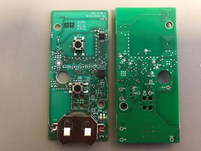
B8QU2
Jul 11, 2021Universal 2 Button Transmitter
Equipment Class
DSC - Part 15 Security/Remote Control Transmitter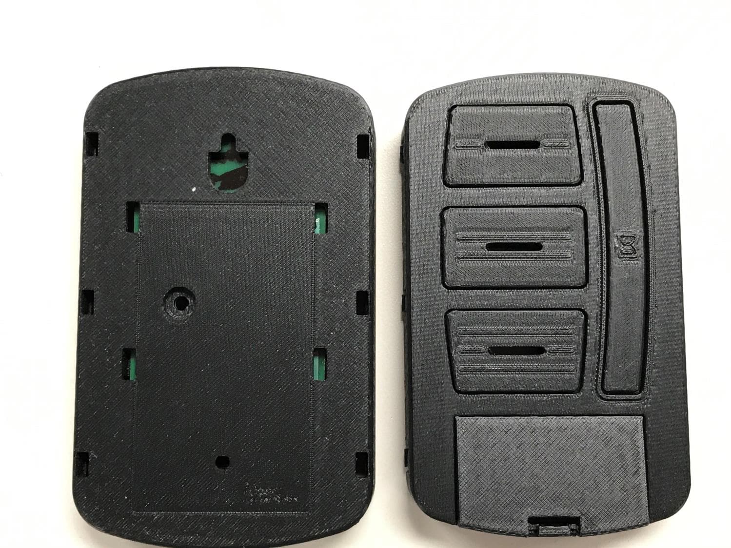
B8QUWWC
Mar 22, 2021Universal Wireless Wall Console
Equipment Class
DSC - Part 15 Security/Remote Control Transmitter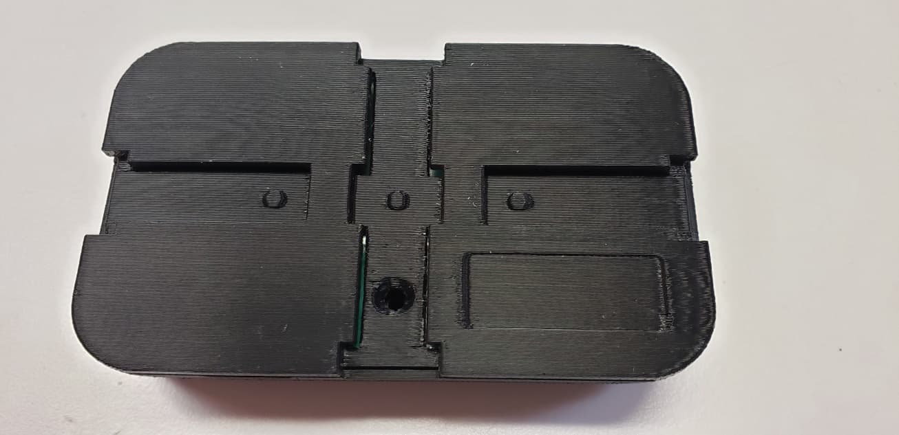
B8Q1BTX
Sep 15, 20201 Button Transmitter
Equipment Class
DSC - Part 15 Security/Remote Control Transmitter