B8QACSDA1GARAGE DOOR OPENER TRANSMITTER
The Genie Company a Division of Overhead Door Corporation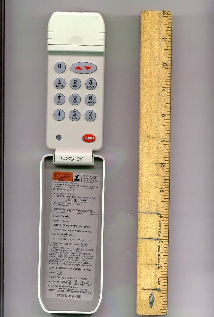
Click to zoom
Application Details
- Equipment Class
- DSC - Part 15 Security/Remote Control Transmitter
- Date of Grant
- Oct 22, 2003
- Application Purpose
- Original Equipment
- Date of Application
- Oct 22, 2003
- Equipment Note
- GARAGE DOOR OPENER TRANSMITTER
- Frequency Range
- 389.50000000 - 390.50000000
- Country
- United States
Documents & Files
Document Text
Text extracted from the exhibit documents filed with the FCC. Open a document above to read the original.
Users Manual
STEP1: SETTINGYOURWIRELESSKEYPADPIN (PERSONALIDENTIFICATIONNUMBER) AActivate programming mode. •Press (in order). –Red LED blinks - once per second. •Enter your PIN (3 to 8 characters). •Press . –Red LED blinks - twice per second and turns off. STEP 1: S ETTINGYOURWIRELESSKEYPADPIN (PERSONALIDENTIFICATIONNUMBER) AActivate programming mode. •Press (in order). –Red LED blinks - once per second. •Enter your PIN (3 to 8 characters). •Press . –Red LED blinks - twice per second and turns off. 3 DEF 1 2 456 7 8 9 0 GHI JKL MNO PQRS TUV WXYZ 9V ¤ This Wireless Keypad is compatible with all INTELLICODE® radio equipped GENIE® products. •Drill with 1/16" Drill Bit •Phillips Screwdriver •Pencil •Mounting Screws INCLUDED inside Battery Compartment Interchangeable Flip-up Cover available in 3 optional Classic Colors to match your home’s exterior decor Red LED indicates Battery Power and Status during Use and Programming Backlit Keypad for Ease of Use at Night Battery Compartment 9 Volt Battery (included) Instructions •Ability to Control up to three Genie® INTELLICODE® Openers •Simple to Program and Install •PIN Codes can be up to 8 Characters •Low Battery Power Indicator •Stays Programmed During Battery Change •Temporary PIN for Special Purpose Access OPERATING INSTRUCTIONS(KEEP FOR FUTURE REFERENCE) A Moving door can cause serious injury or death. 1Keep people clear of opening while door is moving. 2DoNotallow children to play with Wireless Keypad. 3During programming, the door opener could begin to run, so stay away from the moving door and its parts. To keep the door from moving, close the door and disconnect it from the Opener by pulling the Emergency Release. 3528135342 WARNING STEP3: O PERATINGONEDOOROPENER ATo move the garage door: •Enter your PIN. •Press . Proceed to Section 3 - Mounting Instructions. STEP2: P ROGRAMMINGONEDOOROPENER AFind the Learn Code Button and Learn Code Indicator LED on your door opener. –If your door opener has a black antenna wire, the Learn Code Button and Indicator LED are located near the antenna. (The light lens may need to be opened.) –If your door opener does not have an antenna, you have an external receiver. The external receiver cover must be removed to access the Learn Code Button and Indicator LED. •Press the Learn Code Button. – Learn Code Indicator LED (on Opener) will blink. •Enter your PIN and press on keypad. –Learn Code Indicator LED stays on. •Press again. –Learn Code Indicator LED turns off. BASICPROGRAMMING FOR ONE D OOROPENER Red Indicator LED Learn Code Button Located on Opener Housing STEP3: P ROGRAMMINGDOOROPENERS ADecide which door will be door #1, #2 and #3. •Press the Learn Code Button (see Section 1 Step 2). –Learn Code Indicator LED (on Opener) blinks. •Enter your PIN and press . –Learn Code Indicator LED stays on. •Press the number you have picked for this door Opener ( or or ). –Learn Code Indicator LED stays on. • Press . –Learn Code Indicator LED turns off. BRepeat step A above for each door opener. Each door opener must be programmed to receive the signal from the Wireless Keypad. STEP4: O PERATING2 OR3 DOOROPENERS ATo move one of the doors. •Enter your PIN. •Press . •Press door opener number ( or or ). SEE NOTE AT BOTTOM OF SECTION 1 Proceed to Section 3 - Mounting Instructions. PROGRAMMING FOR 2 OR3 DOOROPENERS MOUNTINGINSTRUCTIONS The Keypad must be mounted in sight of the door(s), at least 5 feet above the ground and clear of any moving door parts. AMount Keypad. (Mounting screws located inside battery compartment.) •Remove Battery Cover. See Section 4 Figure 2. • Drill a 1/16” pilot hole for the top mounting screw. •Install a screw into the drilled hole, leaving a 1/8" gap between the screw head and the wall. See Figure 1. •Hook the Keypad over the screw. •Mark, drill pilot hole and fasten bottom screw. •Reinstall Battery Cover. For answers to questions, call 1-800-35 GENIE, or visit www.geniecompany.com Additional Genie® products can be ordered using the Accessories page in your Owner’s Manual or through the 800 number above. FOR CONVENIENCE Program Keypad BEFOREmounting. SECTION 1 SECTION 2 SECTION 3 BASIC ADDITIONALOPERATIONS SECTION 4 USING ATEMPORARYPIN A temporary PIN allows temporary access to your home by repair persons, meter readers, etc. AEnter your PIN •Press . BEnter the Temporary PIN (from 3 to 8 characters). •Press . NOTE • DO NOT reprogram the Door Opener(s). • Temporary PIN remains active until the next time your normal PIN is entered. F ORGOTYOURPIN OR C HANGINGYOURPIN AErase old PIN : •Press and hold in order - . –Red LED will blink once and turn off. •Release all buttons. BProgramming Door Opener(s). •Return to “Programming” Section 1 or Section 2. NOTE • If the door does not move, check the red LED on Keypad. If the LED is blinking rapidly, the PIN was entered incorrectly. After the LED stops blinking, re-enter your PIN and try again. • Any Keypad Button will control the door for 30 seconds after the door starts moving. • Rapid blinking of the red LED indicates an error. After a few seconds the LED will turn off. Start over. Wall screw head gap Figure 1 FOR CONVENIENCE Program Keypad BEFOREmounting. STEP2: PROGRAMMING THEKEYPAD FOR MULTIPLEDOOROPENERS AAll door openers will use the same PIN. •Enter your PIN and press. – Red LED blinks - once per second. •Press again. –Red LED blinks - twice per second. •Press the number of doors (total) you wish to control ( or ). •Press . –Red LED blinks several times and turns off. Program Button FEATURES : T OOLSNEEDED: If Safety Reverse does not work properly: 1Close door and disconnect the Opener using Emergency Release Cord. 2Do notuse door Opener, Remote Controls, or Wireless Keypad. 3Refer to Door and Door Opener Owner’s Manuals before attempting any repairs. 1" 8 Printed in the U.S.A. ©2003 The Genie Company, D.B.A. GMI Holdings, Inc. FCC and IC CERTIFIED This device complies with FCC Part 15 and RSS 210 of Industry Canada. This equipment has been tested and found to …
Text truncated - open the document above for the full version.
Cover Letter(s)
FCCLTR.jpg (1195x1672x16M jpeg)
External Photos
genie pix 1.jpg (1263x1874x16M jpeg) genie pix 2.jpg (1263x1874x16M jpeg) genie pix 3.jpg (1263x1874x16M jpeg) genie pix 4.jpg (1263x1504x16M jpeg)
ID Label/Location Info
genie label.jpg (1269x1279x16M jpeg)
ID Label/Location Info
label location.jpg (1263x1874x16M jpeg)
Internal Photos
genie pix 1.jpg (1263x1874x16M jpeg) genie pix 2.jpg (1263x1874x16M jpeg) genie pix 3.jpg (1263x1874x16M jpeg) genie pix 4.jpg (1263x1504x16M jpeg)
Contact Information
Applicant
Mike Whitley(RF Engineer)
Test Firm
Product Safety Engineering, Inc.Steven Hoke
Technical Specifications
| # | Rule Parts | Frequency Range | Power Output |
|---|---|---|---|
| 1 | 15.231 | 389.5 MHz - 390.5 MHz | - |
Other Applications from The Genie Company a Division of Overhead Door Corporation
B8QALDCM2
Jun 05, 2026Door COntrol Module
Equipment Class
DSC - Part 15 Security/Remote Control TransmitterB8QALDPS2
May 29, 2026Door Position Sensor
Equipment Class
DTS - Digital Transmission System
B8QU2
Jul 11, 2021Universal 2 Button Transmitter
Equipment Class
DSC - Part 15 Security/Remote Control Transmitter
B8QUWWC
Mar 22, 2021Universal Wireless Wall Console
Equipment Class
DSC - Part 15 Security/Remote Control Transmitter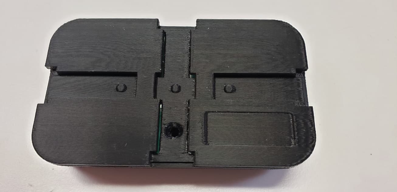
B8Q1BTX
Sep 15, 20201 Button Transmitter
Equipment Class
DSC - Part 15 Security/Remote Control Transmitter