BDZFD100SLPersonal Help Button/Auto-Alert Help Button
Lifeline Systems Inc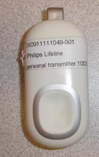
Click to zoom
Application Details
- Equipment Class
- DSR - Part 15 Remote Control/Security Device Transceiver
- Date of Grant
- Nov 01, 2012
- Application Purpose
- Original Equipment
- Date of Application
- Oct 29, 2012
- Equipment Note
- Personal Help Button/Auto-Alert Help Button
- Frequency Range
- 319.50000000 - 319.50000000
- Company
- Lifeline Systems Inc
- Country
- United States
Documents & Files
Document Text
Text extracted from the exhibit documents filed with the FCC. Open a document above to read the original.
Users Manual
AutoAlert Help Button for Senior Livi Instructions For Use FDI OOSL PHILIPS ng 0940823_AA_User MANUAL_SL091 21 2.indd 1 + 9/19/12 9:17 AM JmSRI 0940823AA_User MANUAL_SLO91 21 2.indd 9/19/12 9:17 AM + Contents VVarnings 4 AutoAlert Help Button Overview 8 Important Reminders What to Expect If You Fall Adjusting the Neck Cord Recommended Usage 11 Cleaning 12 Troubleshooting 12 Frequently Asked Questions 13 Regulatory Compliance 14 Welcome! This manual explains how your AutoAlert help button allows you to call for help at the press of a button. In addition, if the AutoAlert button detects a fall, it can automatically call for help. Before using your AutoAlert you should read and understand this manual, paying careful attention to the warnings below. 3 0940823_PA_User MANUALSLO91212.indd 3 9/19/12 9:17 AM I I I I VVarn ings Front View WARNING indicates the potentially hazardous situation which, if these Button instructions are not followed, could Push here to result in possible injury, death, or send a Help Call. other serious adverse reaction. Always press your AutoAlert Button if you need help even if you fall. The AutoAlert Help Button may not detect every fall • Examples include, but are not limited to: - A gradual slide such as from a seated position - Lowering oneself slowing to the ground (to brace the impact of a fall) - A fall that is less than a vertical distance of 100 cm can also affect the ability of the device to detect a fall. Always press your button if you need help. • Certain conditions can affect the ability of the AutoAlert Help Button to detect a fall. - If you live at an altitude above 6,600 feet - If you are less than 4 feet 6 inches in height - If you weigh less than 88 pounds The ability to send a help call by pressing the button is not affected. Getting up from a fall will cancel the automatic Help Call If the AutoAlert Help Button detects that you have gotten up within 30 seconds of a fall being detected, a Help Call will not be generated. Do not attempt to stand if you feel unable to. If you think you need assistance, press your Help Button immediately to initiate the Help Call. 4 O94O823_AAUsor MANUAL_SL091 21 2.indd 4 9/19/12 9:17AM + I __ Neck Cord Strangulation Risk One advantage of the AutoAlert Help Button being worn as a pendant is that the button is accessible by either of your hands. However, any cord worn around the neck can pose a strangulation risk, including the possibility of death and serious injuries. This may be of more concern to wearers in wheelchairs, using walkers, using beds with guard rails, or who might encounter other protruding objects upon which the cord can become tangled. • The neck cord provided on the AutoAlert Help Button is designed to break apart under certain conditions to reduce the risk of strangulation. If the neck cord breaks ask for a replacement. • Do not use any other neck cord than the one provided by Lifeline. Other neck cords may not provide the feature to break apart therefore increasing the risk of strangulation. + The AutoAlert Help Button will not work when outside the coverage range established on your campus. • The AutoAlert Help Button is a radio frequency (RF) device that transmits a signal to the CarePoint system on your campus which sends a message to a staff member in your community who can respond. The CarePoint system may provide coverage within your campus, and this button can not summon assistance if you travel off the campus. • The signal range may be affected by environmental factors, including building materials, large masses covering the AutoAlert Help Button (e.g., a person falling on top of ii), and submersion in liquid. 5 O94B23_AA_UserMANUAL_SL_O91212indd 5 9/19/12 9:17AM + I Keeping the Vent Hole Clear of Obstructions The vent located on the back of the AutoAlert Help Button is part of the fall detection sensor system and needs to remain clear of obstructions (e.g., lint or food products). A continuous flow of water (e.g., a shower) hitting the vent directly may also temporarily obstruct the vent. However your AutoAlert Help Button is waterproof and should be worn at all times — even when bathing or showering. AutoAlert Help Button is Waterproof • Your AutoAlert Help Button is waterproof and should be worn at all times — even when bathing or showering. • The AutoAlert Help Button has a water resistance rating of IPX7 which means that it can withstand being submerged up to a depth of 1 meter for 30 minutes. Electromagnetic Interference The AutoAlert Help Button may interfere with certain electrical equipment, such as magnetic resonance imaging (MRI) medical equipment. It may also interfere with aircraft communications, so do not take the AutoAlert Help Button aboard an airplane. You may pack the AutoAlert Help Button in checked luggage. 6 CAUTION indicates the potential of device malfunction, device failure, damage of the device, or damage to other property. And, if these instructions are not followed, may result in minor or moderate injury. 0940823_AA_User MANUAL_SL_091 21 2.indd 6 9/19/12 9:17AM 1 I I I I I I Servicing the Device There are no user-serviceable parts inside the AutoAlert Help Button. Do not attempt to open or modify the device. Device Battery • The AutoAlert Help Button has a built-in lithium battery that provides a long service life without the need for replacement or recharging by the user. The user does not need to monitor the battery life as this is done automatically by the AutoAlert Help Button. The AutoAlert Help Button will automatically send a signal when the battery will soon need to be replaced, and a staff member will contact you to replace it with a new button. • It is important to start using your replacement button immediately when received and return your old button. The sensors that are used to detect falls will be disabled when there are approximately 7 days of battery life remaining. This is to conserve battery life for generating Help Calls initiated by a button…
Text truncated - open the document above for the full version.
Cover Letter(s)
PHILIPS Attention: Application Examiner Re: Request for confidentiality Applicant: Philips Home Monitoring/Lifeline System Company FCC ID: BDZFD100SL To whom it may concern, Permanent Confidentiality Request is hereby submitted by Philips Home Monitoring/Lifeline System Company to withhold permanently from public review certain portions of the application for equipment certification for the referenced FCC identifiers. This request for confidentiality is made pursuant to 47 CFR 0.457(d) and 0.459 of the FCC Rules. In particular, the following sections of the application are to be kept pennanently confidential: • L7lenxiI d EmhlpilolDs • Run • Sth •• czilt Rationale for request for confidentiality: Philips Home Monitoring/Lifeline System Company has invested considerable time and materials in research and development to produce the referenced product. Disclosure of the permanently confidential portions of this application to competitors would not only give them significant competitive advantages in developing similar products, but would also disclose successful implementation of unpublished, leading edge technology developed by us. Sincerely, Carlos 0. A costa Senior Quality & Regulatory Affairs Manager Philips Home Monitoring/Lifeline System Company www.lifelinesys.com Philips Lifeline 111 Lawrence Street Framingham, MA 01702 (1)
External Photos
Report No. 3192128BOX-002 Lifeline Systems Inc. Page 3 of 13 Issued: 04-Jan-2010 Revised: None Photo 1 - External Front view Photo 2 - External Back View 3.0 Product Photographs 1 2 ED 16.3.15 (3/12/08) Informative
Test Report
This report is for the exclusive use of Intertek's Client and is provided pursuant to the agreement between Intertek and its Client. Intertek's responsibility and liability are limited to the terms and conditions of the agreement. Intertek assumes no liability to any party, other than to the Client in accordance with the agreement, for any loss, expense or damage occasioned by the use of this report. Only the Client is authorized to permit copying or distribution of this report and then only in its entirety. Any use of the Intertek name or one of its marks for the sale or advertisement of the tested material, product or service must first be approved in writing by Intertek. The observations and test results in this report are relevant only to the sample tested. This report by itself does not imply that the material, product, or service is or has ever been under an Intertek certification program. Non-Specific EMC Report Shell Rev. May 2012 Page 1 of 36 EMC TEST REPORT Report Number: 100764703BOX-001a Project Number: G100764703 Report Issue Date: 7/12/2012 Product Designation: FD100SL Standards: FCC 47CFR Part 15 Subpart C Section 15.231 (2012) Industry Canada RSS-210 Issue 8 December 2010 Industry Canada RSS-Gen Issue 3 December 2010 Tested by: Client: Intertek Testing Services NA, Inc. 70 Codman Hill Road Boxborough, MA 01719 Philips Lifeline 111 Lawrence Street Framingham, MA 01702 Report prepared by Reviewer Report reviewed by Nicholas Abbondante/Staff Engineer Vathana F. Ven/Senior Project Engineer Intertek Report Number: 100764703BOX-001a Issued: 07/12/2012 Non-Specific EMC Report Shell Rev. May 2012 Page 2 of 36 1 Introduction and Conclusion The tests indicated in section 2.0 were performed on the product constructed as described in section 4.0. The remaining test sections are the verbatim text from the actual data sheets used during the investigation. These test sections include the test name, the specified test Method, a list of the actual Test Equipment Used, documentation Photos, Results and raw Data. No additions, deviations, or exclusions have been made from the standard(s) unless specifically noted. Based on the results of our investigation, we have concluded the product tested complies with the requirements of the standard(s) indicated. The results obtained in this test report pertain only to the item(s) tested. 2 Test Summary Section Test full name Result 3 Client Information 4 Description of Equipment Under Test 5 System Setup and Method 6 Fundamental Field Strength (CFR47 Part 15 Subpart C Section 15.231(b) IC RSS-210 Annex 1.1.2 and Table A) Pass 7 Occupied Bandwidth (CFR47 Part 15 Subpart C Sections 15.215, 15.231(c) IC RSS-Gen Section 4.6, IC RSS-Gen A1.1.3) Pass 8 Radiated Spurious Emissions (CFR47 Part 15 Subpart C Sections 15.205, 15.209, and 15.231(b)(1-3), IC RSS-Gen Section 7.2.2 Table 3 and Section 7.2.5 Table 5, IC RSS-210 Annex 1.1.2 and Table A) Pass 9 Duty Cycle (CFR47 Part 15 Section 15.35 and Subpart C Section 15.231(b)(2) IC RSS-Gen Section 4.5) Pass 10 5 Second Shut Off Time (CFR47 Part 15 Subpart C Section 15.231(a)(1) IC RSS-210 Section A1.1.1(a)) Pass 11 AC Line-Conducted Emissions (CFR47 FCC Part 15 Subpart C 15.207; IC RSS-Gen Section 7.2.4) N/A, Battery 12 Revision History Intertek Report Number: 100764703BOX-001a Issued: 07/12/2012 Non-Specific EMC Report Shell Rev. May 2012 Page 3 of 36 3 Client Information This EUT was tested at the request of: Company: Philips Lifeline 111 Lawrence Street Framingham, MA 01702 Contact: Clyde Dottin Telephone: 508-988-1313 Fax: 240-536-3263 Email: [email protected] 4 Description of Equipment Under Test Equipment Under Test Description Manufacturer Model Number Serial Number Emergency Alert Pendant (US Version) Philips Lifeline FD100SL BOX1206150828-001 Emergency Alert Pendant (US Version) Philips Lifeline FD100SL BOX1206150828-003 Receive Date: 06/15/2012 Received Condition: Good Type: Production Description of Equipment Under Test (provided by client) The FD100SL is an emergency alert pendant Equipment Under Test Power Configuration Rated Voltage Rated Current Rated Frequency Number of Phases 3.6Volt Battery NA NA NA Operating modes of the EUT: No. Descriptions of EUT Exercising 1 BOX1206150828-001 is configured as a normal operating device 2 BOX1206150828-003 is configured to transmit nearly continuously Intertek Report Number: 100764703BOX-001a Issued: 07/12/2012 Non-Specific EMC Report Shell Rev. May 2012 Page 4 of 36 5 System Setup and Method Cables ID Description Length (m) Shielding Ferrites Termination NONE Support Equipment Description Manufacturer Model Number Serial Number NONE 5.1 Method: Configuration as required by ANSI C63.4 (2003) 5.2 EUT Block Diagram: Intertek Report Number: 100764703BOX-001a Issued: 07/12/2012 Non-Specific EMC Report Shell Rev. May 2012 Page 5 of 36 6 Fundamental Field Strength 6.1 Method Tests are performed in accordance with FCC 47CFR Part 15 Subpart C Section 15.231 and RSS 210 TEST SITE: 10m ALSE The 10m ALSE is 13m (Length) x 21m (Depth) x 10m (Height) with the effective size in terms of space from the tips of the absorber is 12m (Length) x 20m (Depth) x 8.5m (Height). This chamber achieves broadband performance using a unique arrangement of hybrid and ferrite tile absorber. This chamber has a built in 3m diameter turntable (Embedded type). The metal structure of the table makes electrical connection around the entire circumference of the turntable to the ground plane with a metal brush type connection. The turntable is located on one end of the chamber and the antennas are mounted 3 and 10 meters away at the other end of the chamber on the adjustable an Antenna Mast. The antenna mast is a non-conductive bore sighted type with remote control of antenna height and polarization. The Antenna Mast and the turntable can be remotely controlled through the controller located in the adjacent Control room. A wooden table 80 cm high is used for table-top equipment. Measuremen…
Text truncated - open the document above for the full version.
Test Setup Photos
Intertek Report Number: 100764703BOX-001a Issued: 07/12/2012 Non-Specific EMC Report Shell Rev. May 2012 Page 19 of 36 8.4 Setup Photographs: Orientation 1 Intertek Report Number: 100764703BOX-001a Issued: 07/12/2012 Non-Specific EMC Report Shell Rev. May 2012 Page 20 of 36 Orientation 2 Intertek Report Number: 100764703BOX-001a Issued: 07/12/2012 Non-Specific EMC Report Shell Rev. May 2012 Page 21 of 36 Orientation 3
Contact Information
Applicant
Roberto Ballester(Principal Design Quality Engineer)
Test Firm
Intertek Testing Services NA Inc.Yaqing Liu
[email protected]978 635 8662
Technical Specifications
| # | Rule Parts | Frequency Range | Power Output |
|---|---|---|---|
| 1 | 15.231 | 319.5 MHz - 319.5 MHz | - |
Other Applications from Lifeline Systems Inc
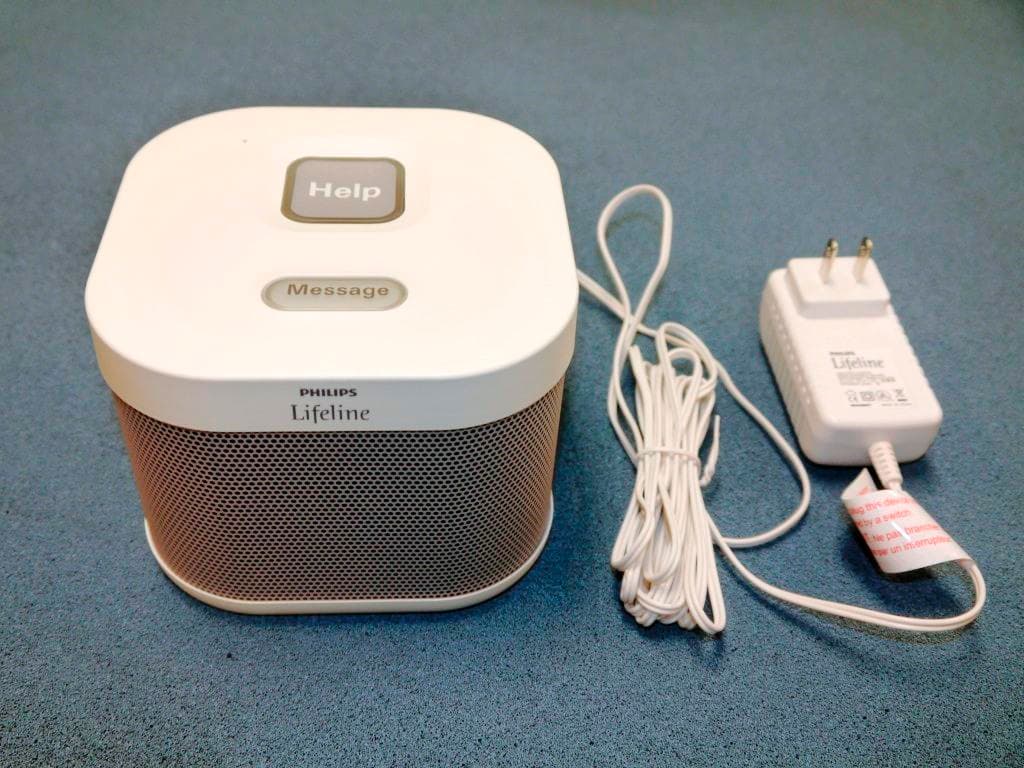
BDZ7200C
Jan 26, 2020Wireless Communicator
Equipment Class
PCB - PCS Licensed Transmitter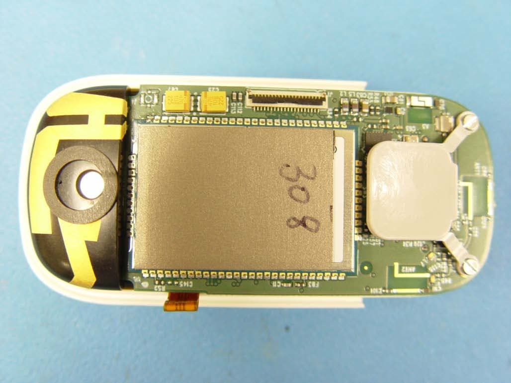
BDZ7000MHB
Sep 19, 2013Mobile Help Button (MHB) for a Personal Emergency System (PERS)
Equipment Class
PCT - PCS Licensed Transmitter worn on body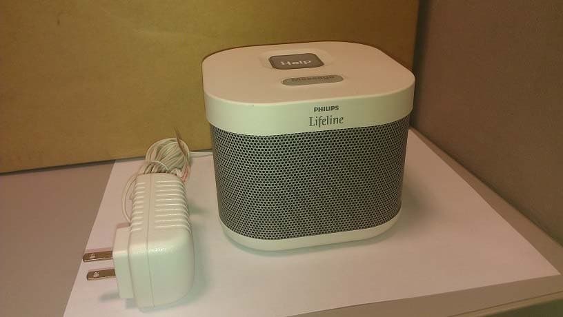
BDZ7000C
Sep 12, 2013Calgary communicator unit with ISM, GSM, WCDMA
Equipment Class
DXX - Part 15 Low Power Communication Device Transmitter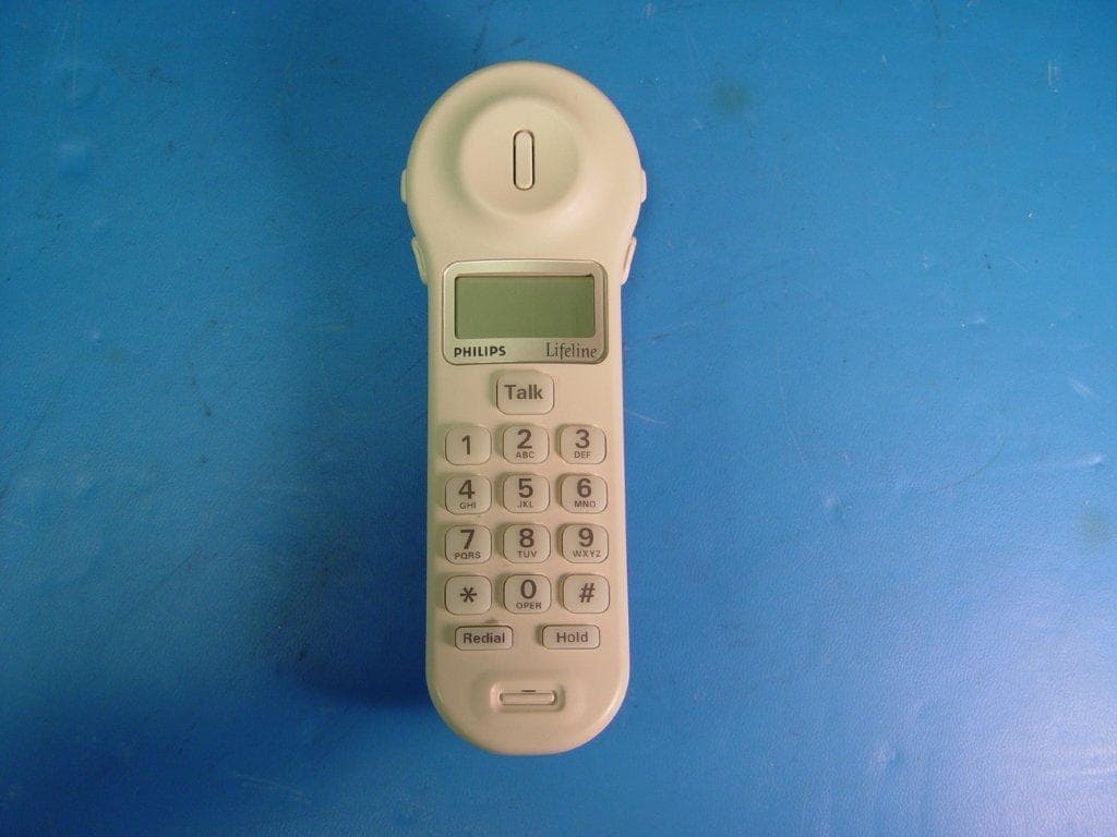
BDZ1000
Sep 27, 2012Philips Lifeline Cordless Phone Communicator
Equipment Class
PUE - Part 15 Unlicensed PCS portable Tx held to ear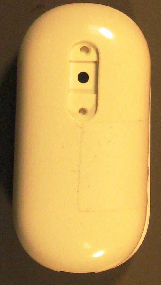
BDZFD100
May 11, 2010AutoAlert Help Button
Equipment Class
DSC - Part 15 Security/Remote Control Transmitter