BZ5MX1000UX1000 Watt UHF Translator
Larcan Inc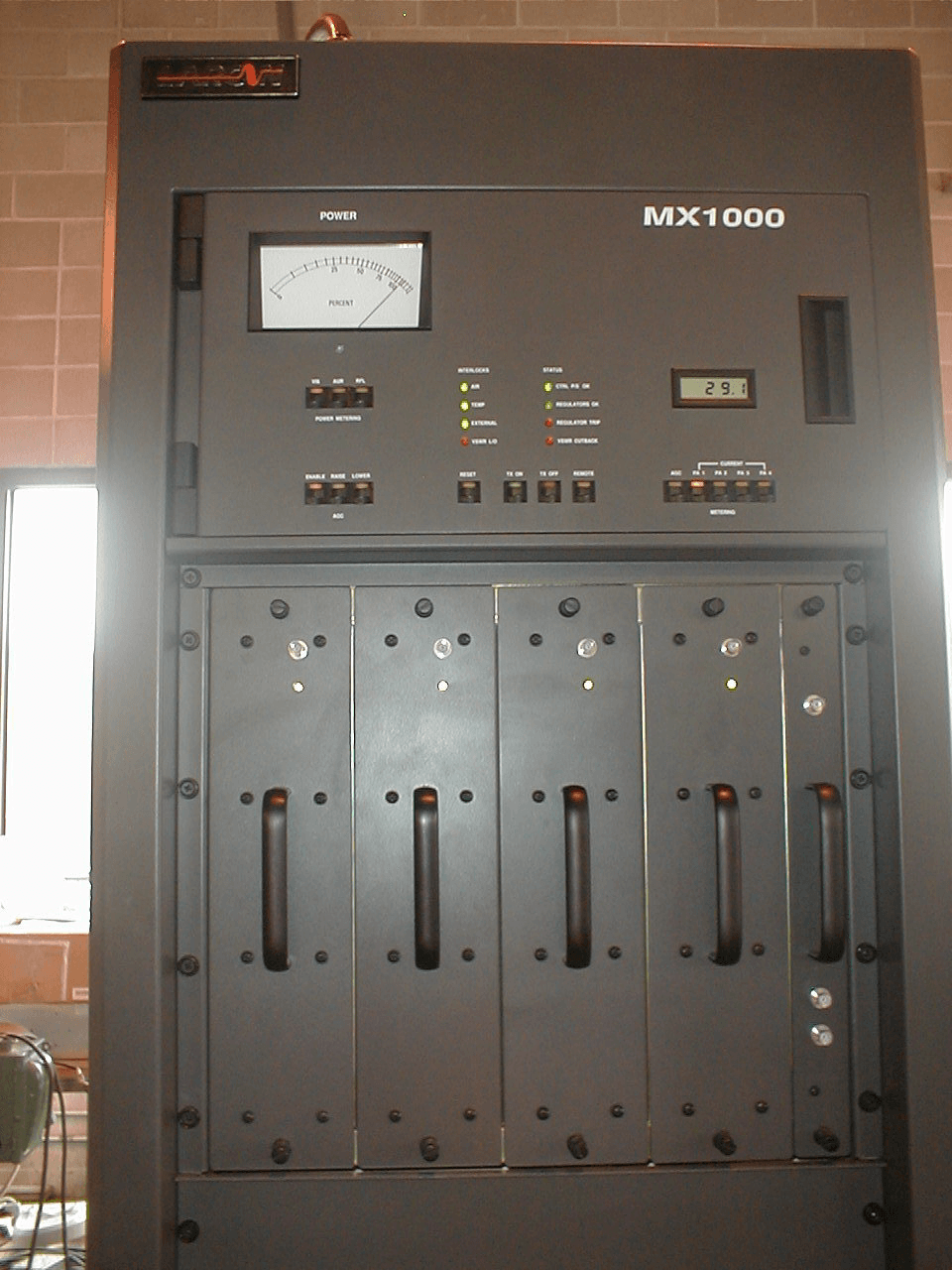
Click to zoom
Application Details
- Equipment Class
- TBC - Licensed Broadcast Station Transmitter
- Date of Grant
- Jul 29, 2004
- Application Purpose
- Original Equipment
- Date of Application
- Jun 27, 2004
- Equipment Note
- 1000 Watt UHF Translator
- Frequency Range
- 470.00000000 - 806.00000000
- Company
- Larcan Inc
- Country
- Canada
Documents & Files
Document Text
Text extracted from the exhibit documents filed with the FCC. Open a document above to read the original.
Users Manual
1 Publication TSM 20-319 TECHNICAL MANUAL 1KW UHF INTERNALLY DIPLEXED TV TRANSMITTER MX1000U SERIES LARCAN INC. 228 AMBASSADOR DRIVE MISSISSAUGA, ONTARIO CANADA L5T 2J2 PHONE: (905) 564-9222 FAX: (905) 564-9244 Rev 1: March 2003 2 INTRODUCTION This manual describes the LARCAN model MX1000U, internally diplexed UHF television transmitter. LARCAN all-solid-state 1 kW UHF transmitters are designed to operate conservatively at 1 kW peak sync visual/vision RF power and 100W average aural/sound single carrier RF power, with superb performance, reliability and operating economy. The MX1000U transmitter accepts an on-channel internally diplexed (in a 10:1 ratio vis to aur/snd) composite driving signal of 10 mW peak visual RF, as input to its RF chain. The 1 kW transmitter is self-contained within a single 19" cabinet with an integral cooling fan and filtered rear door air intake. The simplicity of design, the employment of modular subassemblies, and the use of standard readily available components, also enhances serviceability. Important transmitter parameters are monitored, and can be displayed on the meters built into the transmitter control panel. Additionally, telemetry readings are made available as DC signals for monitoring by remote control systems. The MX1000U, like all other LARCAN transmitting equipment, is suitable for unattended remote-control operation. AMPLIFIER CHAIN (REFER TO FIGURE 1) The Aural signal of the transmitter is diplexed (at IF) with the visual/vision signal within the exciter (hence the term "internally diplexed), and is amplified in common with the visual signal in the above amplifier chain (hence the term common amplification). The internally diplexed composite RF output of the exciter/translator is fed to a 4-way active splitter. The 4 outputs of the splitter are fed to conservatively designed broadband solid-state amplifiers. The outputs from the four PA modules are combined for the total transmitter output power. These amplifiers require no tuning or adjustment. Phasing for the four PA modules is done at the splitter level. Internal cable lengths and precise production tolerances allow for a very small adjustment range for phasing. Simplicity of operation, reduced maintenance costs and increased reliability are a few of the major benefits derived from this modular amplifier design. The modules are operated well below their maximum ratings. Each RF power amplifier (PA module) is fully modular within itself and each module has a gain equivalent to the entire gain of the transmitter (see Figure 2). Each PA module has it's own preamplifier, Intermediate PA, Driver and PA section. The front end preamplifier on the PA module monitors and provides soft startup, overdrive and VSWR protection for the module itself (independent of the transmitter protection). The output stage of the module consists of three amplifier "pallets" each consisting of two push-pull LDMOS FET amplifiers that operate in class AB, and are combined in quadrature. The outputs of these pallets are further combined in a 3- way combiner. The amplifier module is rated for 350 watts, and in the present four PA module system is operated at a total transmitter power of 1 kW sync peak + 100 watts aural/sound. The module is provided with a test jack for monitoring. The amplifier output is fed to the bandpass filter and a directional coupler, which provides a small sample of forward and reflected output power for metering, AGC and VSWR supervisory functions. An additional sample is available for monitoring and transmitter setup. The transmitter output then passes to the antenna system. TRANSMITTER CONTROL The control circuitry in this solid state transmitter is straightforward and simple. The use of latching type relays ensures that the transmitter state (on/off, or trip status) is “remembered” under power failure conditions. Interlocking is provided for loss of airflow and for over temperature conditions. An additional interlock connection point is provided for interlocking the transmitter to an external patch panel. 3 Facilities are provided on the control board for telemetry, status, and control connections to and from a remote control system. These are available on 25 pin D-sub connector. For remote control operation, simply press the REMOTE switch (LED illuminated). This places +12V on Remote Enable line and allows the transmitter to be turned on and off via remote control. In this mode the transmitter cannot be turned on locally but for safety purposes, the transmitter can always be turned off locally while in REMOTE. The Remote Enable +12V appears as an arming signal at J5-5. A momentary connection of this +12V to J5-13 turns the transmitter ON, and momentary connection of the +12V to J5-8; turns the transmitter OFF. Control circuit power for the transmitter is supplied by two redundant power supplies wired in parallel. The failure of either power supply will not affect the operation of the transmitter. The transmitter's power supply consists of two ferro-resonant transformers each with dual secondary windings. Each transformer secondary feeds a rectifier/filter and linear regulator combination. The regulator modules are located inside the rear door of the transmitter and can be removed for servicing by first disconnecting the two cables and then unplugging the module. This can be done without turning off the transmitter. A two pole fused disconnect or breaker is required for transmitter connection from line-to-line. The transmitter is wired per Figure 5. • Press the OFF button on the control panel. Pull out the regulators so they are no longer mating with their respective AC power connectors. Turn on the power supply breakers. Press the ON button. Looking into the back of the transmitter DS6 and DS7 on the AC distribution board should be illuminated (refer to figure 3). If the blower comes on and DS6 and DS7do not, then the AC Distribution board needs to be bench tested. • Press the OFF button again. …
Text truncated - open the document above for the full version.
Operational Description
BZ5MX1000UX Application for FCC Certification Demodulator Input 1000 Watt UHF Translator OPERATIONAL DESCRIPTION This application requests authorization for video/audio input to our 1000W UHF Translator, BZ5MX1000UX. The Translator will be driven directly by a color television demodulator. The intended use of the MX1000UX is to rebroadcast a television translator relay station of other legal source of video and audio. The MX1000UX is a solid-state Translator designed to operate at 1kW peak sync visual RF power and 100W average aural single carrier RF power. The MX1000UX Translator accepts an on-channel internally diplexed composition driving signal of 10mW peak visual RF, as input to its RF chain. The MX1000UX Translator is self-contained within a single 19” cabinet with an integral cooling fan and filtered rear door air intake. The simplicity of design, the employment of modular subassemblies, and the use of standard, readily available, components also enhance serviceability. The unit tested specifically for this application was operated on Channel 38. This channel was chosen to provide protection to and from existing radio services, and to facilitate the measurement of possible spurious products conducted or radiated from the 1000W UHF Translator. The input signals used in the equipment application tests were generated by a color bar generator driving a General Instruments Demodulator and General Instruments Modulator which are typically the units used. However, due to varying customer requirements, other demodulators are available upon customer request. The published specifications on any demodulator used in this equipment will meet or exceed FCC specifications. The General Instruments Demodulator of this translator will accept video and audio from the television relay station. The Demodulator splits the video and audio signals and provides the General Instruments Modulator with video and audio or a composite signal. The Modulator then generates both video and audio or composite signal to the customer’s required frequency. Frequency spacing, deviation, and other characteristics including distortion are therefore determined solely by the originating television station. It is anticipated that the translator will be driven directly by the demodulator output of an FM microwave repeater. No provision is made for tampering with or adjusting the composite video or audio signal except for depth of video modulation. Therefore, all aspects of the input video signal are determined solely by the originating television station. The MX1000UX meets all the requirements for unattended operation. A description of the automatic control circuitry can be found in the user’s manual. Station identification requirements will be supplied by the originating station. Wiring, shielding and construction are in accordance with accepted principles of good engineering practice. The translator’s construction is such that all hazardous components are enclosed of protected against accidental contact by operating personnel. Door interlocks and grounding switches are not required as the highest DC voltage, which is accessible under normal use, is 12V.
Parts List/Tune Up Info
BZ5MX1000UX Application for FCC Certification Demodulator Input 1000 Watt UHF Translator ACTIVE DEVICES AND FUNCTION LIST DEVICE TYPE FUNCTION MODULE: UHF Visual/Aural RF Detector #41D1607 Q1, Q6, Q12, MPS8598 General Purpose Q14 Q2, Q7, Q11, MPS6515 Amplifier Q13 Q3, Q8 2N5771 Hi-speed Switching Q4, Q9 2N4351 N-CH Switching Q5, Q10 2N4401 General Purpose Q15, Q16, Q17 MPSH17 VHF Mixer U1, U8 TDA2595 Horizontal Combination U2, U7 74LS221N Monostable Multivibrator U3 MC78L05CP +5V Voltage Regulator U4, U5, U6, LM358N Op Amp U9, U10 MODULE: Power Amplifier Interface PCB #21B1789 U1 74HC08AD Quad 2 I/P AND Gate VR1 MC78L05ACD +5V Voltage Regulator MODULE: Front End Amplifier #21B1752 Q1 MMBT2222ALT1 General Purpose U1 MHW9182 Hybrid Amplifier U2 to U6 LM324D Op Amp VR1 MC7824CD2T +24V Voltage Regulator BZ5MX1000UX Application for FCC Certification Demodulator Input 1000 Watt UHF Translator ACTIVE DEVICES AND FUNCTION LIST DEVICE TYPE FUNCTION MODULE: Intermediate Power Amplifier #21B1791 Q1, Q2 MRF181S 4W Mosfet Q3 MMBT2907ALT1 General Purpose U1 MC1723CD Adjustable Voltage Regulator MODULE: Driver Pallet #21B1751 Q1 MRF374 Power Mosfet U1 MC78M09CDT +9V Voltage Regulator MODULE: Pallet Amplifier #21B1639 Q1, Q2 MRF374 Power Mosfet U1 MC78M09CDT +9V Voltage Regulator MODULE: Linear Regulator #41D1673 Q3 TIP36C Bipolar Power Q4, Q5, Q7 2N7002LT1 N-CH Mosfet U1 MC1723CD Adjustable Voltage Regulator U2 MC74AC11D Triple 3 I/P NAND Gate U3 MC14050BD Hex Buffer/Non Inverting U4 MC3423D Voltage Sensor U5, U11, U15, MOC212S Opto-isolator U21 to U24 U6 LM319H Linear Hi-speed Comparator U7, U8, U9 LF351D Wideband Op Amp BZ5MX1000UX Application for FCC Certification Demodulator Input 1000 Watt UHF Translator ACTIVE DEVICES AND FUNCTION LIST DEVICE TYPE FUNCTION MODULE: Linear Regulator #41D1673 U10, U29 MC74AC109D 2 I/P AND Gate U12, U16, U18, LM555CM Binary Decoder U26, U41 U14, U28 MC74HC393D Dual Binary Counter U17, U25 MC74AC32D Quad 2 I/P OR Gate U20, U27, U40, MC74AC04D Hex Inverter U42 U30, U31 MC74AC08D Quad 2 I/P AND Gate U33, U34 MOC3041S Opto-isolator VR1 TL431ACD Programmable Precision Vltg Regulator MODULE: Control PCB #30C2065 Q1 to Q18 MSD601-RT1 Small Signal U1, U2, U9, U10, LM324D Dual Op Amp U14, U28, U29, U31, U32, U35 U3, U34, U37 MC14066BD Quad Bilateral Switch U5, U11, U12, MOCD207 Dual Opto-isolator U13, U15, U21, U22, U24, U25, U26, U27, U45, U46 U7, U36, U39 MC14490DW Hex Contact Bounce Eliminator U8, U41 LM555CM Binary Decoder U16, U17, U20, U33 MMPQ2222A General Purpose Amp U18, U23 MC14053BD Triple 2-CH Multiplexer/Demultiplexer U19 MC14073BD Triple 3 I/P AND Gate U30 MC14528BD Dual Monostable Multivibrator U38 74HC08AD Quad 2 I/P AND Gate U40, U42 74HC04AD Hex Inverter BZ5MX1000UX Application for FCC Certification Demodulator Input 1000 Watt UHF Translator ACTIVE DEVICES AND FUNCTION LIST DEVICE TYPE FUNCTION MODULE: Control PCB #30C2065 (cont'd) U43 X9C103P Digital Pot VR1, VR2 MC34064P5 Under-voltage sensing MODULE: AC Distribution PCB #30C2064 Q1, Q2 2N2222 General Purpose U1 LM324N Dual Op Amp U2, U6 ILQ1 Opto-isolator U3, U4, U5 MC34161P Power Supply Monitor 30C2065G1 CONTROL BOARD TABLE OF CONTENTS 1. INTRODUCTION.............................................................................................................1 2. CIRCUIT DESCRIPTION..................................................................................................2 General...............................................................................................................................2 On/Off Control And Interlock Functions ................................................................................2 Metering Display Circuitry ...................................................................................................2 AGC And VSWR Protection .................................................................................................3 Interconnection With The Transmitter ...................................................................................4 Remote Control ..................................................................................................................5 3. TESTING AND TROUBLESHOOTING..............................................................................6 Metering switches................................................................................................................6 Interlocks............................................................................................................................7 Control................................................................................................................................7 Remote Status and Telemetry interface................................................................................7 AGC Circuitry......................................................................................................................8 4. PARTS LIST....................................................................................................................8 LIST OF FIGURES Figure Description 1. Front Panel 2. Rear View of Control panel 3a through 3f: Schematic Diagram 30C2065S 4. Assembly Diagram 30C2065 1. INTRODUCTION The MX1000 control system is completely self contained on a hinged panel at the front of the transmitter. From this panel, the user can turn the transmitter on and off, raise and lower the output power, and monitor all critical parameters and status. The interface for remote control of the transmitter is also provided from this panel. The control system handles all the interlocking control, protects the transmitter against excessive VSWR and displays power supply status. Meters are provided for monitoring output power, reflected power, P/S currents and AGC voltage. Figure 1 Front Panel 30C2065G1 CONTROL BOARD 2. CIRCUIT DESCRIPTION GENERAL The circuitry is generally divided into various functional sections. Each section performs different fu…
Text truncated - open the document above for the full version.
Schematics
ON CMD TO BLOWER J8-37 J8-39 J8-40 EMERGENCY INTERLOCK PS1 Breaker On PS2 Contactor On Cmd AC to Blower AC Present on PS1 Breaker AC Connection made by wiring AC directly to the terminals on the breaker Blower Wiring Ok PS1 Contactor On Cmd Pins 1 and 2 go to AC Coil on Ferro 2 Contactor Pins 3 and 4 go to AC Coil on Ferro 1 Contactor Pin 1: AC input on Blower connection Pin 2: Wiring interlock for the blower connection. Pin 3: AC input on Blower connection Pin 4: Gnd to Blower PS3 Contactor On Cmd Pins 5 and 6 go to AC Coil on Ferro 3 Contactor * Future Use To Ferro Transformer 2 Contactor AC Connection made by wiring AC directly to the terminals on the breaker To Ferro Transformer 2 Contactor AC Present on PS2 Breaker AC Connection made by wiring AC directly to the terminals on the breaker AC Present on PS3 Breaker To Ferro Transformer 3 Contactor Connection made by wiring directly to the terminals on the breaker To Ferro Transformer 3 Contactor To Ferro Transformer 1 Contactor To Ferro Transformer 1 Contactor PS2 Breaker On L2 BLOWER ON CMD K5-11 L2 L1 TX ON CMD +12V +12V +12V +5V R33 1K JP1 DS9 DS1 CR7 1N4001 R47 51K J7 1 2 R36 51K DS6 DS11 K6 DS2E-S-DC12V 4 68 13 119 161 K5 DS2E-S-DC12V 4 68 13 119 161 R46 51K J2 1234 R2 51K R1 51K R48 51K DS8 R41 51K CB3 AM2-A9A8AW 12 34 CR8 1N4001 R45 51K CB1 AM2-A9A8AW 12 34 CB2 AM2-A9A8AW 12 34 DS10 K8 DMP6402A 4 3 1 2 DS12 K7 DMP6402A 4 3 1 2 K4 DS2E-S-DC12V 4 68 13 119 161 DS2 CB4 AM2-A9A8AW 12 34 K3 T92S11A12-240 4 2 8 6 91 + C12 220uF R42 51K DS13 CR9 1N4001 DS7 J1 123456 R34 51K DS14 K9 DMP6402A 4 3 1 2 DS5 R35 51K CB2 L2CB1 L1CB1 L2CB4 L1CB2 L1CB4 L2 PS2 FAIL J8-32 J1-1 J1-2J8-31 PS1 FAIL To Regulator 1 To Regulator 2 To Regulator 3 To Regulator 4 To PS1 To PS2 To Control PCB30C2065 Pins 2 and 4wire to theSplitter To Control PCB 30C2065 To Regulator 5 To Regulator 6 L1 L2 PS1 STATUS PS2 STATUS K5-11 TX ON CMD PS1 STATUS BLOWER ON CMD PS2 STATUS L2 L1 -12V +12V +5V +5V +5V +5V -12V +5V +12V +5V +5V +5V +5V +5V -12V -12V -12V -12V -12V +12V +12V +12V +12V +12V +12V +12V +5V-12V+12V -12V+12V+5V + C1 10uF C4 330pF M8 CR6 80SQ040 R31 2K J8 1 2 3 4 5 6 7 8 C7 .1uF J6 1 2 3 4 5 6 7 8 9 10 11 12 13 14 15 J4 1 2 3 4 5 6 7 8 9 10 11 12 13 14 15 F2 F1 F3 L14 L18 R22 2K7 R9 1K L15 R32 9K1 J10 1 2 3 4 L22 J11 1 2 3 4 5 6 7 8 CR4 80SQ040 R27 1K J5 1 2 3 4 5 6 7 8 9 10 11 12 13 14 15 L2 L16 L10 L3 C9 .1uF R26 9K1 L4 L19 L21 J9 1 2 3 4 5 6 7 8 L23 C8 .1uF L17 R30 8K2 CR5 80SQ040 L9 + C2 10uF U5 MC34161 1 2 3 45 6 7 8 1 2 3 45 6 7 8 L8 DS4 R25 1K R24 7K5 L13 L7 L24 L11L12 C6 330pF R23 8K2 U3 MC34161 1 2 3 45 6 7 8 1 2 3 45 6 7 8 J3 1 2 3 4 5 6 7 8 9 10 11 12 13 14 15 C10 330pF R8 2K7 U4 MC34161 1 2 3 45 6 7 8 1 2 3 45 6 7 8 L5 + C3 10uF CR3 80SQ040 CR1 80SQ040 M9 1 CR2 80SQ040 DS3 R28 1K L6 M7 L20 M6 R29 2K J13 1 2 3 4 5 6 7 8 9 10 11 12 13 14 15 M5 M3 F4 M4 J14 1 2 3 4 5 6 7 8 9 10 11 12 13 14 15 R7 7K5 L25 J12 1 2 3 4 5 6 7 8 9 10 11 12 13 14 15 16 17 18 19 20 21 22 23 24 25 26 27 28 29 30 31 32 33 34 35 36 37 38 39 40 M1 AIR CAB 2 (SH.4) SH.4 & 5 ) LOCKOUT J3-39 (SH.4) (SH.6) CAB 1 (SH.7) J17-25 AIR (SH.5) CAB 1 AIR J11-23 EXT CAB 1 TEMP J11-22 (SH.6) ON (SH.4) (SH.4) (SH.6) EXT CAB 2 (SH.5) + (SH.6) (SH.4) OFF J3-37 CAB 2 TEMP TEMP J17-24 (SH.5) J11-7 CAB 2 AIR LOCAL/REMOTE J4-37 (SH.6) CAB 1 J11-21 TEMP J11-6 VSWR J4-39 + (SH.7) + J3-1 RESET J4-1 (SH.5) U16-7 SH.5 1.1 RN-01-063 MAR.28/01 J.M. 1 RN-01-050 MAR.6/01 J.M. 2 RN-01-095 APR.6/01 J.M. P.H. P.H. (SH.4) LAST REF.DESIGN. CR34 C144 DS16 J17 K12 L7 Q18 R287 S25 U53 VR2 NOTE: P.H. 3 RN-01-103 APR.17/01 J.M.P.H. (SH.6) 4 RN-01-XXX OCT29/01 J.M. Cab 2 Temp Ok REMOTE ARM Active Low Reset Cab 2 Air Ok Cab 1 Temp Ok VSWR OUT TRIP V LOCK REMOTE ARM LOCAL ARM Cab 1 Air Ok BLOWER ON CMD REMOTE OFF CMD CAB A ON CMD REMOTE ON CMD Ext Ok RESET SW Active High Reset TRIP BLINKER CAB B ON CMD Vswr Lockout +12V +12V +12V +12V +12V +12V +12V +5V +12V +12V +12V +12V +12V +12V +12V +12V +12V +12V +12V +12V +12V +12V +12V +12V +12V +12V +12V +12V +12V +12V +12V +12V +12V +12V +12V +12V +5V +12V U20A MMPQ2222A 1 15 162 C79 330pF R83 4K7 R96 10K U22A MOCD207 1 2 8 7 U19A 14073 1 2 8 9 14 7 C78 330pF U17C MMPQ2222A 5 11 126 R36 4K7 R82 100 DS1 CR22 HSMS-2800 U17D MMPQ2222A 7 9 108 R84 100 K3 TQ2SA-L2-12V 8 3 2 1 5 6 10 9 7 4 R111 1K5 DS2 CR19 HSMS-2800 U23 14503 2 4 6 10 12 14 1 15 3 5 7 9 11 13 16 8 I1 I2 I3 I4 I5 I6 DA DB O1 O2 O3 O4 O5 O6 +12V GND U15A MOCD207 1 2 8 7 R113 1K U19B 14073 3 4 5 6 C75 330pF U17A MMPQ2222A 1 15 162 U19C 14073 11 12 13 10 U17B MMPQ2222A 3 13 144 U15B MOCD207 3 4 6 5 DS9 R85 10K K6 TQ2SA-L2-12V 8 3 2 1 5 6 10 9 7 4 U18 14503 2 4 6 10 12 14 1 15 3 5 7 9 11 13 16 8 I1 I2 I3 I4 I5 I6 DA DB O1 O2 O3 O4 O5 O6 +12V GND K9 TQ2SA-L2-12V 8 3 2 1 5 6 10 9 7 4 U24A MOCD207 1 2 8 7 R88 10K CR13 HSMS-2800 DS12 CR20 HSMS-2800 CR17 HSMS-2800 DS11 R104 1K U21A MOCD207 1 2 8 7 R77 10K U25A MOCD207 1 2 8 7 CR16 HSMS-2800 C74.01uF R101 1K5 R92 10K R76 2K U21B MOCD207 3 4 6 5 CR9 HSMS-2800 R94 1K5 R105 1K5 U22B MOCD207 3 4 6 5 R86 1K5 K8 TQ2SA-L2-12V 8 3 2 1 5 6 10 9 7 4 CR18 HSMS-2800 K5 TQ2SA-L2-12V 8 3 2 1 5 6 10 9 7 4 S10 21 4 65 8 3 7 109 S11 21 4 65 8 3 7 109 R120 1K C77 330pF R56 1K R106 1K5 C83 330pF C68 1uF R110 1K5 R98 1K5 R114 1K5 C90 330pF C71 1uF R65 1K R91 100 C86 1uF CR15 HSMS-2800 K7 TQ2SA-L2-12V 8 3 2 1 5 6 10 9 7 4 C76 .01uF R95 100 R102 1K5 R260 10K DS7 R87 2K R261 10K CR14 HSMS-2800 R90 10K C81 330pF R100 1K5 R97 1K5 U26A MOCD207 1 2 8 7 CR10 HSMS-2800 C82 330pF C63 330pF R109 1K5 C84 330pF C80 330pF K4 TQ2SA-L2-12V 8 3 2 1 5 6 10 9 7 4 R71 1K R89 10K DS8 R93 1K5 R79 2K DS10 R259 100K R62 1K R108 1K5 S12 21 4 65 8 3 7 109 C53 330pF C73 .01uF U27B MOCD207 3 4 6 5 S13 21 4 65 8 3 7 109 U27A MOCD207 1 2 8 7 L1 CR11 HSMS-2800 R103 1K5 J2 1 2 3 4 5 6 7 8 9 10 C85 330pF R107 1K R81 100 U26B MOCD207 3 4 6 5 CR21 HSMS-2800 R213 1K CR12 HSMS-2800 R99 1K PA4 (SH.3) (SH.5) PA3 PA6 PA2 (SH.5) PA1 PA5 VAGC (SH.3) PA8 PA7 PA2PA2 PA4 PA5 ANALOG PA2 PA3 AGC V S2 S3 DTT1000SU PA6 PA1 PA3 AGC V DTT500SU S4 …
Text truncated - open the document above for the full version.
Test Report
BZ5MX1000UX Application for FCC Certification Demodulator Input 1000 Watt UHF Translator FREQUENCY DRIFT VS TEMPERATURE S890D DEMODULATOR/C8ML MODULATOR MEASURED DEGREES C LO FREQUENCY(Hz) DEVIATION(Hz) DEVIATION(%) -30BC 555,249,600 -43 -0.000008 -20BC 555,249,401 -242 -0.000044 -10BC 555,249,274 -369 -0.000066 0BC 555,249,330 -313 -0.000056 +10BC 555,249,475 -168 -0.000030 +20BC 555,249,598 -45 -0.000008 +25BC 555,249,643 0 0(REF) +30BC 555,249,782 +139 +0.000025 +40BC 555,249,949 +306 +0.000055 +50BC 555,249,856 +213 +0.000038 FCC Specification: Frequency Stability of Carrier +0.002%. BZ5MX1000UX Application for FCC Certification Demodulator Input 1000 Watt UHF Translator FREQUENCY DRIFT VS TEMPERATURE BLOCK DIAGRAM Test Equipment List Power Supply - Hewlett Packard HP6012A S/N 2329A-02181 Frequency Counter - Hewlett Packard HP5334B S/N 2937A05503 Thermometer - Fluke 77/80T-150U Thermostatically Controlled Temperature Chamber - Associated Variac Power Supply Frequency Counter Temperature Chamber Thermometer LO Demodulator Modulator
Test Report
BZ5MX1000UX Application for FCC Certification Demodulator Input 1000 Watt UHF Translator OUTPUT STABILITY OF AGC INPUT LEVEL(dB) RELATIVE OUTPUT POWER dB = 100% Output Power -20 -0.1 -15 -0.1 -10 0 -5 0 500uV=0dB 0.0 (Ref) +5 0 +10 0 +15 -0.1 +20 +0.1 -20 -0.1 -15 0 -10 0 -5 0 1000uV=0dB 0.0 (Ref) +5 0 +10 0 +15 0 +20 +0.1 -20 0 -10 0 -5 0 5000uV=0dB 0.0 (Ref) +5 0 +10 0 +15 -0.1 +20 0
Test Report
BZ5MX1000UX Application for FCC Certification Demodulator Input 1000 Watt UHF Translator POWER MEASUREMENTS Power requirements for the 1000 Watt UHF Translator were determined as follows: 1. The translator's visual power meter measures the peak visual power by reading the average levels of a detected sample of the output. The meter is calibrated by multiplying the above visual power reading by 168%. The visual metering circuitry has a negligible response to the aural power due to the large (>10MHz) detector bandwidth. When the detector bandwidth is this large, the detector does not peak detect the intercarrier beat product. 2. The aural power is measured by reading the peak level of the detected 4.5MHz intercarrier product. The level of this product has a direct correspondence to the aural power and is independent of the visual power as long as the peak visual power exceeds the aural power. SUPPLY CURRENT SUPPLY CURRENT MEASURED MEASURED TO O/P DEVICES TO O/P DEVICES VISUAL PWR AURAL PWR VISUAL ONLY VISUAL & AURAL NOTE 1 NOTE 2 NOTE 3 NOTE 3 595 Watts 100 Watts 3.85 Amps 4.15 Amps Note 1: Measured on the Bird Model 43 Wattmeter with the visual carrier modulated by the standard synchronizing signal at 75% of peak amplitude and the aural carrier disabled. Note 2: Measured on the Bird Model 43 Wattmeter with the visual carrier disabled. Note 3: The voltage across the output devices on all models in +28 volts. The output devices are operated Class 'AB'.
Test Report
BZ5MX1000UX Application for FCC Certification Demodulator Input 1000 Watt UHF Translator OVERALL GROUP DELAY FREQUENCY(MHz) OVERALL DELAY(nS) 0.20 0(Ref) 0.40 +10 0.60 -15 0.80 -10 1.00 -20 1.20 -15 1.40 +30 1.60 +10 1.80 -20 2.00 +15 2.20 +10 2.40 +50 2.60 +30 2.80 +10 3.00 +30 3.20 +10 3.40 -60 3.58 -100 3.80 -210 4.00 -270 4.18 -260
Test Report
BZ5MX1000UX Application for FCC Certification Demodulator Input 1000 Watt UHF Translator TEST BLOCK DIAGRAM Test Equipment List Translator – MX1000UX S/N 9820-7 Demodulator – S890D S/N 02L0000106166 Power Meter – Bird Model 43 S/N 216291 Directional Coupler – Larcan 6920-1800 Load – Dielectric 5750 S/N 2354 Oscilloscope – Tektronix 2465 S/N B025622 Spectrum Analyzer – Hewlett Packard HP8591E S/N 3325A01739 Dipole Antenna Cut to Frequency (for field strength measurements only) Translator w/Demodulator Power Meter Directional Coupler Load Detector Spectrum Analyzer Oscilloscope Dipole Ant
Contact Information
Applicant
John E. Tremblay(Engineering, Vice President)
Technical Contact
LARCAN Inc.John E Tremblay
[email protected]905 564 9222
228 Ambassador Drive · Mississauga, Ontario · Canada
Non-Technical Contact
LARCAN Inc.John E Tremblay
[email protected]905 564 9222
Technical Specifications
| # | Rule Parts | Frequency Range | Power Output | Emission | Tolerance |
|---|---|---|---|---|---|
| 2 | 74 | 470 MHz - 806 MHz | 100 W | 250KF3E | 0.002 % |
Other Applications from Larcan Inc
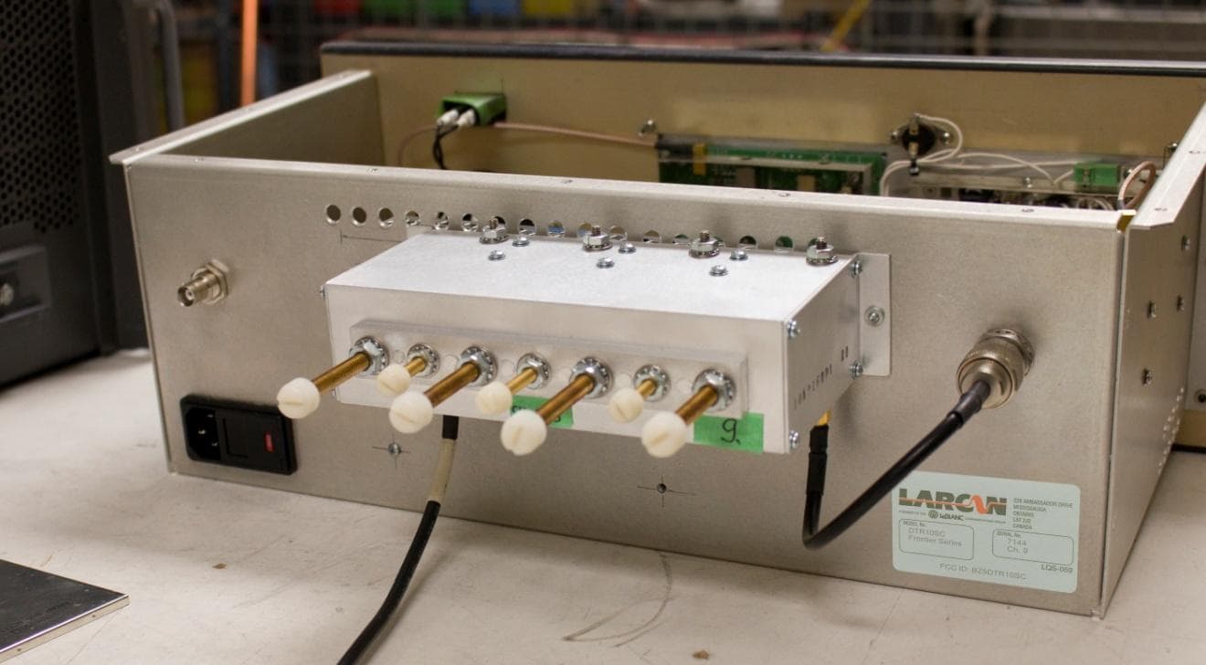
BZ5DTR10SC
Jun 16, 2014Digital Television Translator
Equipment Class
TBC - Licensed Broadcast Station Transmitter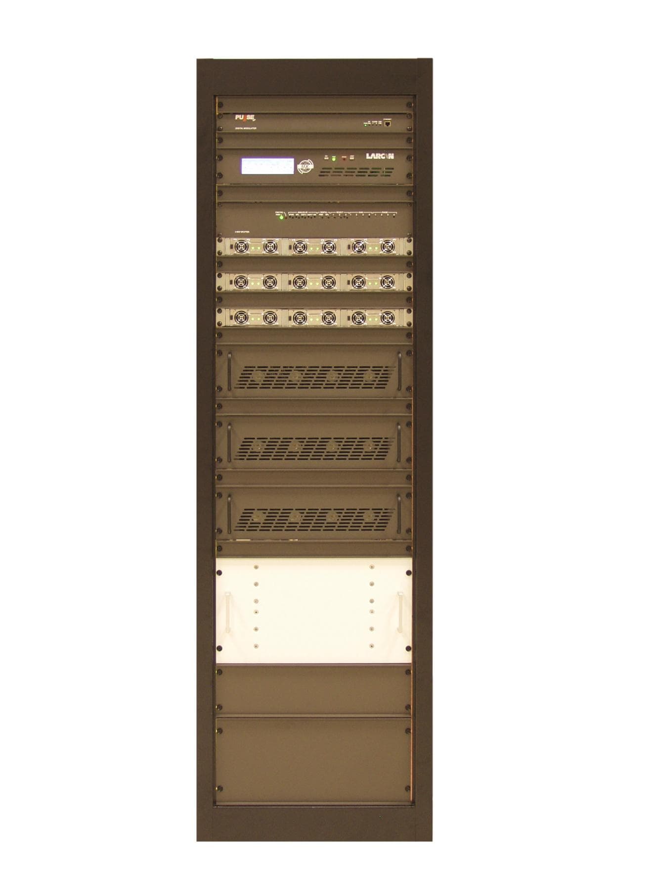
BZ5MXI1503U
Aug 04, 2013Television Broadcast Translator
Equipment Class
TBC - Licensed Broadcast Station Transmitter
BZ5MXI1002U
Jul 11, 2012Digital Television Translator
Equipment Class
TBC - Licensed Broadcast Station Transmitter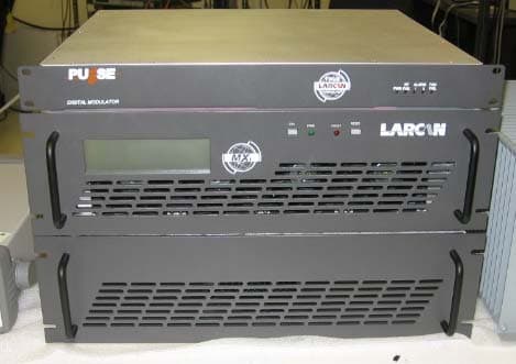
BZ5MXI501U
Nov 22, 2010Digital Television Broadcast Translator
Equipment Class
TBC - Licensed Broadcast Station TransmitterBZ5DTT250M
Jul 22, 2010Digital Television Broadcast Translator
Equipment Class
TBC - Licensed Broadcast Station Transmitter