BZ5MX20UTranslator
Larcan Inc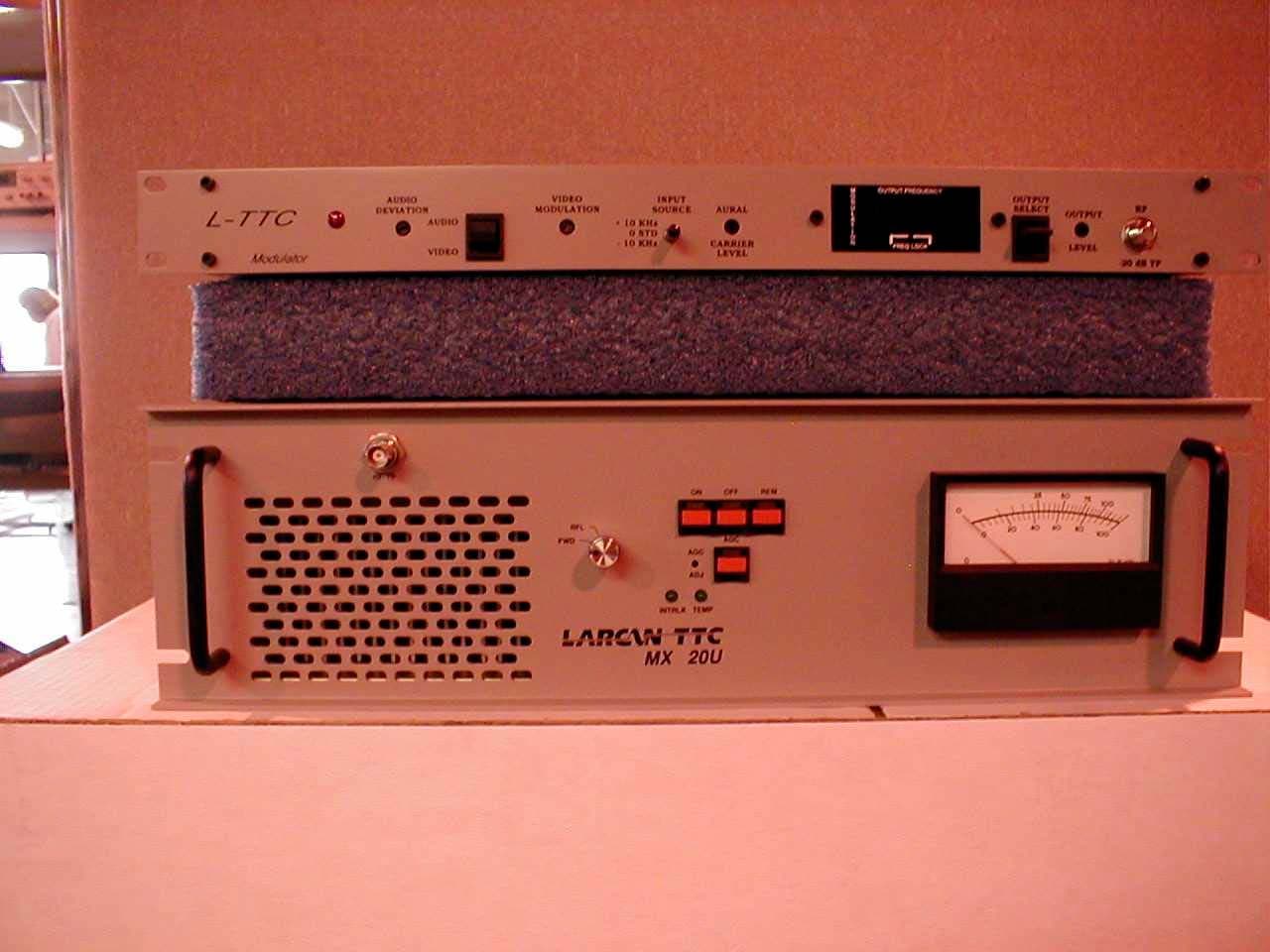
Click to zoom
Application Details
- Equipment Class
- TBC - Licensed Broadcast Station Transmitter
- Date of Grant
- May 23, 2002
- Application Purpose
- Original Equipment
- Date of Application
- Mar 17, 2002
- Equipment Note
- Translator
- Frequency Range
- 470.00000000 - 806.00000000
- Company
- Larcan Inc
- Country
- Canada
Documents & Files
Document Text
Text extracted from the exhibit documents filed with the FCC. Open a document above to read the original.
Users Manual
PUBLICATION TSM 20-311 TECHNICAL MANUAL 20 WATT UHF AMPLIFIER FOR MX20U SERIES TV TRANSMITTER/TRANSLATOR LARCAN INC. 228 AMBASSADOR DRIVE MISSISSAUGA, ONTARIO CANADA L5T 2J2 PHONE:(905) 564-9222 FAX:(905) 564-9244 Rev 0: December 1, 1999 MX Series - 20 Watt UHF AMPLIFIER TSM 20-311 rev 0: December 1, 1999120 W UHF Amplifier SectionTitlePage NOTICES, ETC. ..................................................................................................................3 SAFETY AND HEALTH WARNINGS ............................................................................. 4&5 GENERAL SERVICE INFORMATION 1) Parts Lists Explained..........................................................................................5 2) Interpreting LARCAN Drawing Numbers............................................................5 3) The LARCAN Assembly Prefix Numbering System ...........................................6 4) List of Prefix Numbers for the 20W Amplifier .....................................................7 5) Production Changes ...........................................................................................7 INTRODUCTION .................................................................................................................8 GENERAL DESCRIPTION..................................................................................................8 SPECIFICATIONS.............................................................................................................10 ABOUT THIS MANUAL .....................................................................................................11 PUBLICATIONS LIST for MX series 20W UHF Amplifier: PUB99-36 20W UHF Amplifier Installation: 1.General Information..............................................................................36-1 2.Grounding and Ground Loops ..............................................................36-2 3.Lightning and other Transient Protection .............................................36-4 4.Power Wiring ........................................................................................36-9 5.Ventilation and Air Conditioning .........................................................36-10 6.Fire Protection ....................................................................................36-11 7.Unpacking ..........................................................................................36-12 8.Transmitter External Interlock Connections .......................................36-12 9.On Site: First Time Start-up................................................................36-13 PUB99-37 20W UHF Amplifier (Prefix 1): 1.Amplifier Chassis Description...............................................................37-1 MX Series - 20 Watt UHF AMPLIFIER TSM 20-311 rev 0: December 1, 1999220 W UHF Amplifier SectionTitlePage PUB99-38 Heatsink Assembly (Prefix 2): 1.Heatsink Assembly Description............................................................38-1 2.Front End Module .................................................................................38-2 3.IPA1 Module.........................................................................................38-2 4.PA Module............................................................................................38-4 5.Directional Coupler ...............................................................................38-5 6.RF Metering Board Description (Prefix 5) ............................................38-6 7.RF Metering Board Test and Calibration ..............................................38-6 PUB99-39 20W Control Panel & Metering: 1.Control Panel Description.....................................................................39-1 2.Control Board Assembly Description....................................................39-2 PUB99-91 Basic Transmitter Maintenance: 1.General.................................................................................................91-1 2.Daily .....................................................................................................91-1 3.Weekly..................................................................................................91-2 4.Monthly .................................................................................................91-2 5.Semi-annually and Annually .................................................................91-2 6.Transmitter Cooling System .................................................................91-2 7.Static 1, Equipment 0: A brief Static Tutorial........................................91-3 8.FET and Surface Mount Replacement .................................................91-4 9.Replacement Parts ...............................................................................91-7 10.Spare Parts Recommendations ...........................................................91-9 MX Series - 20 Watt UHF AMPLIFIER TSM 20-311 rev 0: December 1, 1999320 W UHF Amplifier NOTICES, ETC.: THIS EQUIPMENT USES STATIC-SENSITIVE CMOS INTEGRATED CIRCUITS. Observe proper handling precautions (indicated in Maintenance Sections) at all times when working with this equipment. TOXIC MATERIALS NOTICE... IMPORTANT... Effective thermal management in certain semiconductor devices in this equipment is possible only through the use of Beryllium Oxide ceramic materials. This equipment contains devices made with Beryllium Oxide! Beryllium and its compounds is a POISON if taken into the body in any manner. To reduce your risk, remember: In case of accidental breakage of any kind of semiconductor device, DO NOT INHALE THE DUST, and AVOID GETTING DUST IN YOUR MOUTH; it could contain Beryllium. DO NOT LET BERYLLIUM DUST INTO YOUR BLOODSTREAM THROUGH CUTS OR OPEN WOUNDS! Seek and obtain IMMEDIATE medical attention if the dust enters your body in any manner. Avoid cuts by wearing gloves while picking up the pieces. Wash your hands thoroughly after replacing devices. Dispose…
Text truncated - open the document above for the full version.
Attestation Statements
APPLICATION FOR FCC CERTIFICATION BZ5MX20U MODULATOR INPUT 20 WATT UHF TRANSLATOR EXHIBIT 15 ENGINEER’S STATEMENT I, John Tremblay, do hereby certify that the attached information was prepared by me or under my direction. __________________________ John E. Tremblay, P. Eng. Vice-President Engineering 27 Feb. 2002 __________________________ Date
Cover Letter(s)
APPLICATION FOR FCC CERTIFICATION BZ5MX20U MODULATOR INPUT 20 WATT UHF TRANSLATOR EXHIBIT NO.TITLENO. OF PAGES 1 Supporting Statement, Application5 for FCC Certification of BZ5MX20U 2 Instruction Manuals 2a20W UHF Amplifier Manual 2bCadco M369 Operating Manual 3 Test Measurement Set-up 4 Frequency Drift vs. Temperature2 4aModulator Tabulated Data 4bTemperature Test Set-up 5 Aural Test Set-up 6 Active Devices and Function List 7 FCC Identification Label for BZ5MX20U 8 Power Measurement Statement 9 Attenuation/Swept Sidebands Tabulated Data 10 Video Waveforms3 10aInput Modulated Stair Step 10bOutput Unmodulated Stair Step 10cDifferential Gain 10dDifferential Phase 11 Group Delay2 11aOverall Group Delay Tabulated Data 11bOverall Group Delay Graph 12 Audio Frequency Response, 50% Modulation 13 Audio Frequency Response, 100% Modulation 14 BZ5MX20U Translator Photos4 14aPhoto, Front Overall View of BZ5MX20U 14bPhoto, Front View 14c Photo, Interior View 14dPhoto, Rear View with FCC Label 15 Engineer’s Statement APPLICATION FOR FCC CERTIFICATION BZ5MX20U MODULATOR INPUT 20 WATT UHF TRANSLATOR EXHIBIT 1PAGE 1 This application requests authorization for video/audio input to our 20 Watt UHF Translator, BZ5MX20U (Certification applied for). The amplifier will be driven directly by a color television modulator. The intended use of the BZ5MX20U is to rebroadcast a television translator relay station or other legal source of video and audio. A paragraph by paragraph reference is given herein, presenting the required additional data to that called for on FCC Form 731 for FCC Certification of BZ5MX20U 20 Watt UHF Translator. Exhibits are attached to authenticate this application. If further data is required, it will be furnished on request. The unit tested specifically for this application was operated on Channel 50. This channel was chosen to provide protection to and from existing radio services, and to facilitate the measurement of possible spurious products conducted or radiated from the 20 Watt UHF Translator. The results noted here are “worse case” unless otherwise noted. The input signals used in the tests were generated by a color bar generator driving a Cadco Modulator which is typically the modulator used. However, due to varying customer requirements, other modulators are available on customer request. The published specifications on any modulator used in this equipment will meet or exceed FCC specifications. The output of the 20 Watt UHF Translator was properly terminated with a resistive type RF load. 2.1033(b)(1): Applicant is the manufacturer of the equipment. See FCC Form 731 2.1033(b)(2): See FCC Form 731 2.1033(b)(3): Exhibit 2 (20W UHF Instruction Manual, Cadco M369 Operating Manual) 2.1033(b)(4): Exhibit 6 (Active Devices and Function List) 2.1033(b)(5,6,7): See also, the paragraph by paragraph summary of compliance with Part 74, Sub-part G of the FCC Commission Rules that follow. PART 74.750(c)(1): The frequency stability of this equipment as measured per Part 2.1055 of the rules is much better than required over the specified range of the input voltage and temperature. PART 74.761(a): The frequency stability of the visual carrier is totally dependent upon the modulator. Exhibits 4a and 4b document the measurements made, including method and equipment. Modulator output frequency can be, and is normally set to zero deviation at the output channel. As shown in Exhibit 4a, the typical characteristic variation due to temperature is less than +.02%. This is true for all modulator channels. APPLICATION FOR FCC CERTIFICATION BZ5MX20U MODULATOR INPUT 20 WATT UHF TRANSLATOR EXHIBIT 1PAGE 2 PART 74.750(c)(2): Observations were made on a properly operating translator video to Channel 50 using a Hewlett- Packard 8591E Spectrum Analyzer with a cut to frequency dipole antenna at 10 meters from the translator and rotated to detect maximum radiation. The following signals were present: SPECIFICATION FREQUENCY(MHz)SOURCE LIMIT uVMEASURED uV 1374.50 2 nd Harmonic 700 50 733.00 LO 238133 10 Radiation from the modulator was nil. No spurious products could be detected at 10 meters that were less than 90dB down. Antenna terminal measurements with the 8591E Spectrum Analyzer showed no change due to the modulator since the power amplifier stages are not affected by this modulation. The above tests were performed using the same equipment hook up and methods described in Exhibit 3a. The translator test data compiled for this application was video to Channel 50. Translator operating with a standard video test signal input (modulated stair step and color burst) and a modulated audio carrier at –10dB of peak visual. Results are typical of performance on all channels. PART 74.750(c)(3)(ii): Variations of input voltage +15% (reference +28VDC or 120VAC) during the temperature tests resulted in no discernible frequency variation traceable to the power supply. This is reasonable due to the modulator’s internal regulation. PART 74.750(c)(4): The stability of the modulator’s self-generated RF carrier must be considered to determine the overall 20 Watt UHF Translator’s frequency stability. Exhibits 4a and 4b document the performance measurements made including methods and equipment. PART 74.750(c)(5): This equipment meets all the requirements for unattended operation. A description of the automatic control circuitry can be found in Exhibit 2a. PART 74.750(c)(6): Measurements can be taken while the equipment is in operation. Normal operating constants of the power output stage average +28 volts at 2.9 amps. PART 74.750(c)(7) AND PART 74.783(a)(2): Station identification requirements will be supplied by the originating station. APPLICATION FOR FCC CERTIFICATION BZ5MX20U MODULATOR INPUT 20 WATT UHF TRANSLATOR EXHIBIT 1PAGE 3 PART 74.750(c)(8): Wiring, shielding and construction are in accordance with accepted principles of good engineering practice. Apparatus is constructed on an aluminum chassis suitably protected to resi…
Text truncated - open the document above for the full version.
External Photos
APPLICATION FOR FCC CERTIFICATION BZ5MX20U MODULATOR INPUT 20 WATT UHF TRANSLATOR EXHIBIT 14a PHOTO, FRONT OVERALL VIEW OF BZ5MX20U APPLICATION FOR FCC CERTIFICATION BZ5MX20U MODULATOR INPUT 20 WATT UHF TRANSLATOR EXHIBIT 14b PHOTO, FRONT VIEW
Internal Photos
APPLICATION FOR FCC CERTIFICATION BZ5MX20U MODULATOR INPUT 20 WATT UHF TRANSLATOR EXHIBIT 14c PHOTO, INTERIOR VIEW
Operational Description
APPLICATION FOR FCC CERTIFICATION BZ5MX20U MODULATOR INPUT 20 WATT UHF TRANSLATOR EXHIBIT NO.TITLENO. OF PAGES 1 Supporting Statement, Application5 for FCC Certification of BZ5MX20U 2 Instruction Manuals 2a20W UHF Amplifier Manual 2bCadco M369 Operating Manual 3 Test Measurement Set-up 4 Frequency Drift vs. Temperature2 4aModulator Tabulated Data 4bTemperature Test Set-up 5 Aural Test Set-up 6 Active Devices and Function List 7 FCC Identification Label for BZ5MX20U 8 Power Measurement Statement 9 Attenuation/Swept Sidebands Tabulated Data 10 Video Waveforms3 10aInput Modulated Stair Step 10bOutput Unmodulated Stair Step 10cDifferential Gain 10dDifferential Phase 11 Group Delay2 11aOverall Group Delay Tabulated Data 11bOverall Group Delay Graph 12 Audio Frequency Response, 50% Modulation 13 Audio Frequency Response, 100% Modulation 14 BZ5MX20U Translator Photos4 14aPhoto, Front Overall View of BZ5MX20U 14bPhoto, Front View 14c Photo, Interior View 14dPhoto, Rear View with FCC Label 15 Engineer’s Statement APPLICATION FOR FCC CERTIFICATION BZ5MX20U MODULATOR INPUT 20 WATT UHF TRANSLATOR EXHIBIT 1PAGE 1 This application requests authorization for video/audio input to our 20 Watt UHF Translator, BZ5MX20U (Certification applied for). The amplifier will be driven directly by a color television modulator. The intended use of the BZ5MX20U is to rebroadcast a television translator relay station or other legal source of video and audio. A paragraph by paragraph reference is given herein, presenting the required additional data to that called for on FCC Form 731 for FCC Certification of BZ5MX20U 20 Watt UHF Translator. Exhibits are attached to authenticate this application. If further data is required, it will be furnished on request. The unit tested specifically for this application was operated on Channel 50. This channel was chosen to provide protection to and from existing radio services, and to facilitate the measurement of possible spurious products conducted or radiated from the 20 Watt UHF Translator. The results noted here are “worse case” unless otherwise noted. The input signals used in the tests were generated by a color bar generator driving a Cadco Modulator which is typically the modulator used. However, due to varying customer requirements, other modulators are available on customer request. The published specifications on any modulator used in this equipment will meet or exceed FCC specifications. The output of the 20 Watt UHF Translator was properly terminated with a resistive type RF load. 2.1033(b)(1): Applicant is the manufacturer of the equipment. See FCC Form 731 2.1033(b)(2): See FCC Form 731 2.1033(b)(3): Exhibit 2 (20W UHF Instruction Manual, Cadco M369 Operating Manual) 2.1033(b)(4): Exhibit 6 (Active Devices and Function List) 2.1033(b)(5,6,7): See also, the paragraph by paragraph summary of compliance with Part 74, Sub-part G of the FCC Commission Rules that follow. PART 74.750(c)(1): The frequency stability of this equipment as measured per Part 2.1055 of the rules is much better than required over the specified range of the input voltage and temperature. PART 74.761(a): The frequency stability of the visual carrier is totally dependent upon the modulator. Exhibits 4a and 4b document the measurements made, including method and equipment. Modulator output frequency can be, and is normally set to zero deviation at the output channel. As shown in Exhibit 4a, the typical characteristic variation due to temperature is less than +.02%. This is true for all modulator channels. APPLICATION FOR FCC CERTIFICATION BZ5MX20U MODULATOR INPUT 20 WATT UHF TRANSLATOR EXHIBIT 1PAGE 2 PART 74.750(c)(2): Observations were made on a properly operating translator video to Channel 50 using a Hewlett- Packard 8591E Spectrum Analyzer with a cut to frequency dipole antenna at 10 meters from the translator and rotated to detect maximum radiation. The following signals were present: SPECIFICATION FREQUENCY(MHz)SOURCE LIMIT uVMEASURED uV 1374.50 2 nd Harmonic 700 50 733.00 LO 238133 10 Radiation from the modulator was nil. No spurious products could be detected at 10 meters that were less than 90dB down. Antenna terminal measurements with the 8591E Spectrum Analyzer showed no change due to the modulator since the power amplifier stages are not affected by this modulation. The above tests were performed using the same equipment hook up and methods described in Exhibit 3a. The translator test data compiled for this application was video to Channel 50. Translator operating with a standard video test signal input (modulated stair step and color burst) and a modulated audio carrier at –10dB of peak visual. Results are typical of performance on all channels. PART 74.750(c)(3)(ii): Variations of input voltage +15% (reference +28VDC or 120VAC) during the temperature tests resulted in no discernible frequency variation traceable to the power supply. This is reasonable due to the modulator’s internal regulation. PART 74.750(c)(4): The stability of the modulator’s self-generated RF carrier must be considered to determine the overall 20 Watt UHF Translator’s frequency stability. Exhibits 4a and 4b document the performance measurements made including methods and equipment. PART 74.750(c)(5): This equipment meets all the requirements for unattended operation. A description of the automatic control circuitry can be found in Exhibit 2a. PART 74.750(c)(6): Measurements can be taken while the equipment is in operation. Normal operating constants of the power output stage average +28 volts at 2.9 amps. PART 74.750(c)(7) AND PART 74.783(a)(2): Station identification requirements will be supplied by the originating station. APPLICATION FOR FCC CERTIFICATION BZ5MX20U MODULATOR INPUT 20 WATT UHF TRANSLATOR EXHIBIT 1PAGE 3 PART 74.750(c)(8): Wiring, shielding and construction are in accordance with accepted principles of good engineering practice. Apparatus is constructed on an aluminum chassis suitably protected to resi…
Text truncated - open the document above for the full version.
Test Report
APPLICATION FOR FCC CERTIFICATION BZ5MX20U MODULATOR INPUT 20 WATT UHF TRANSLATOR EXHIBIT 1PAGE 4 AUDIO FREQUENCY RESPONSE REFERENCE 50Hz AT 0dB INTO 600 OHMS MODULATION FREQUENCY(Hz) 50%100% 50 0 0 100 -1.49 -1.36 400 +1.50 +1.50 1000 +1.86 +2.23 5000 +6.98 +9.55 10000 +11.76 +14.73 15000 +14.52 +17.57 Tabulated below are the audio harmonic distortion measurements. AUDIO HARMONIC DISTORTION LEVEL (%) MODULATION FREQUENCY(Hz)50%100% 503.111.31 1002.971.27 4002.991.28 1000 2.931.26 50002.901.25 10000 *1.26 15000 * 1.24 * Distortion measurements above 7.5kHz at 50% modulation levels are impractical. The output noise level (FM measured as prescribed in the band of 50 to 15000Hz) was 55dB below the level representing + 25kHz frequency swing. The system noise output (AM) in the same band was 50dB below the level representing 100% amplitude modulation. The output noise measurement had to be performed with the visual carrier operative because of the translator’s common visual/aural amplifiers. PART 74.750(d)(2): The modulator of this translator will accept audio from the microwave television translator relay station in one of two possible ways. First, when the microwave signal carries the audio at a separation of 4.5MHz, it will be passed through the translator’s modulator multiplexed on the video. Frequency spacing, deviation, and other characteristics including distortion are therefore determined solely by the originating television station. APPLICATION FOR FCC CERTIFICATION BZ5MX20U MODULATOR INPUT 20 WATT UHF TRANSLATOR EXHIBIT 1PAGE 5 The sound carrier deviation was monitored while the frequency vs. temperature measurements were taken, see Exhibit 4a. The equipment meets the + 1kHz requirement. APPLICATION FOR FCC CERTIFICATION BZ5MX20U MODULATOR INPUT 20 WATT UHF TRANSLATOR EXHIBIT 4a FREQUENCY DRIFT VS. TEMPERATURE M369 MODULATOR MEASURED DEGREES CLO FREQUENCY(MHz)DEVIATION(Hz)DEVIATION(%) +50 651,241,054 -10,693 -0.001642 +40 651,244,998 - 6,749 -0.001036 +30 651,249,389 - 2,358 -0.000362 +25 651,251,747 0 +0.0000 +20 651,254,160 + 2,413 +0.000371 +10 651,258,449 + 6,702 +0.001029 00 651,262,385 +10,638 +0.001633 -10 651,265,375 +13,628 +0.002093 -20 651,267,175 +15,428 +0.002369 -30 651,266,810 +15,063 +0.002313 APPLICATION FOR FCC CERTIFICATION BZ5MX20U MODULATOR INPUT 20 WATT UHF TRANSLATOR EXHIBIT 8 Power requirements for the 20 Watt UHF Translator were determined as follows: 1. The translator’s visual power meter measures the peak visual power by reading the average levels of a detected sample of the output. The meter is calibrated by multiplying the above visual power reading by 168%. The visual metering circuitry has a negligible response to the aural power due to the large (>10MHz) detector bandwidth. When the detector bandwidth is this large, the detector does not peak detect the intercarrier beat product. 2. The aural power is measured by reading the peak level of the detected 4.5MHz intercarrier product. The level of this product has a direct correspondence to the aural power and is independent of the visual power as long as the peak visual power exceeds the aural power. This is always true for normal operation. BZ5MX20U POWER MEASUREMENTS SUPPLY CURRENT SUPPLY CURRENT MEASURED MEASURED TO OUTPUT DEVICESTO OUTPUT DEVICES VISUAL POWER AURAL POWERVISUAL ONLY VISUAL & AURAL NOTE 1 NOTE 2 NOTE 3 NOTE 3 12.5 WATTS 2.0 WATTS 2.9 AMPS 2.9 AMPS NOTE 1: Measured on the Model 43 Bird Wattmeter with the visual carrier modulated by the standard synchronizing signal at 75% of peak amplitude and the aural carrier disabled. NOTE 2: Measured on the Model 43 Bird Wattmeter with the visual carrier disabled. NOTE 3: The voltage across the output devices on all models is +28 volts. The output devices are operated Class A. APPLICATION FOR FCC CERTIFICATION BZ5MX20U MODULATOR INPUT 20 WATT UHF TRANSLATOR EXHIBIT 9 ATTENUATION VS. FREQUENCY MODULATING FREQUENCYUPPERLOWER REF=VISUAL CARRIER(MHz) SIDEBAND SIDEBAND FCC LIMIT(dB) FCC LIMIT(dB) +0.2 0 Reference -- -0.5-0.5 -- +0.5-0.1 -- +1.25-0.3 -20>-20 +2.0-0.4 -36>-20 +2.5-0.4 -40>-20 +3.0-0.3 -42>-20 +3.5-0.3 -42>-20 +3.58-0.2 -44>-42 +4.1-0.3 -46>-20 +4.18-0.2 -46>-20 +4.75-20 >-20 -50>-20 +5.0-20 >-20 -50>-20 +6.0-50 >-20 -50>-20 +7.0-50 >-20 -50>-20 +8.0-50 >-20 -50>-20 +9.0-50 >-20 -50>-20 +10.0-50 >-20 -50>-20 APPLICATION FOR FCC CERTIFICATION BZ5MX20U MODULATOR INPUT 20 WATT UHF TRANSLATOR EXHIBIT 11a OVERALL GROUP DELAY FREQUENCY(MHz)OVERALL DELAY (nS) 0.20 0 (Reference) 0.40 -40 0.60 -30 0.80 -20 1.00-10 1.20 -30 1.40 +20 1.60 0 1.80 -10 2.00 0 2.20 +10 2.40 -10 2.60 +10 2.80 0 3.00-40 3.20 -60 3.40 -100 3.58 -165 3.80 -250 4.00-280 4.18 -300
Test Report
APPLICATION FOR FCC CERTIFICATION BZ5MX20U MODULATOR INPUT 20 WATT UHF TRANSLATOR EXHIBIT 1PAGE 2 PART 74.750(c)(2): Observations were made on a properly operating translator video to Channel 50 using a Hewlett- Packard 8591E Spectrum Analyzer with a cut to frequency dipole antenna at 10 meters from the translator and rotated to detect maximum radiation. The following signals were present: SPECIFICATION FREQUENCY(MHz)SOURCE LIMIT uVMEASURED uV 1374.50 2 nd Harmonic 700 50 733.00 LO 238133 10 Radiation from the modulator was nil. No spurious products could be detected at 10 meters that were less than 90dB down. Antenna terminal measurements with the 8591E Spectrum Analyzer showed no change due to the modulator since the power amplifier stages are not affected by this modulation. The above tests were performed using the same equipment hook up and methods described in Exhibit 3a. The translator test data compiled for this application was video to Channel 50. Translator operating with a standard video test signal input (modulated stair step and color burst) and a modulated audio carrier at –10dB of peak visual. Results are typical of performance on all channels. PART 74.750(c)(3)(ii): Variations of input voltage +15% (reference +28VDC or 120VAC) during the temperature tests resulted in no discernible frequency variation traceable to the power supply. This is reasonable due to the modulator’s internal regulation. PART 74.750(c)(4): The stability of the modulator’s self-generated RF carrier must be considered to determine the overall 20 Watt UHF Translator’s frequency stability. Exhibits 4a and 4b document the performance measurements made including methods and equipment. PART 74.750(c)(5): This equipment meets all the requirements for unattended operation. A description of the automatic control circuitry can be found in Exhibit 2a. PART 74.750(c)(6): Measurements can be taken while the equipment is in operation. Normal operating constants of the power output stage average +28 volts at 2.9 amps. PART 74.750(c)(7) AND PART 74.783(a)(2): Station identification requirements will be supplied by the originating station.
Contact Information
Applicant
John E. Tremblay(Engineering, Vice President)
Technical Contact
LARCAN INCJohn E Tremblay
[email protected]905-564-9222
228 Ambassador Drive · Mississauga, Ontario · Canada
Non-Technical Contact
LARCAN USA INCPaula A Cooper
[email protected]303-665-8000
Technical Specifications
| # | Rule Parts | Frequency Range | Power Output | Emission | Tolerance |
|---|---|---|---|---|---|
| 2 | 74G | 470 MHz - 806 MHz | 2 W | 250KF3E | 1 Amp |
Other Applications from Larcan Inc
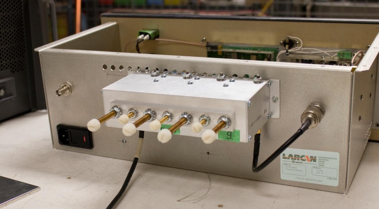
BZ5DTR10SC
Jun 16, 2014Digital Television Translator
Equipment Class
TBC - Licensed Broadcast Station Transmitter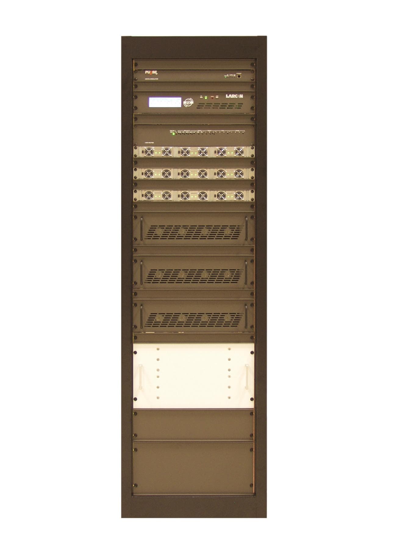
BZ5MXI1503U
Aug 04, 2013Television Broadcast Translator
Equipment Class
TBC - Licensed Broadcast Station Transmitter
BZ5MXI1002U
Jul 11, 2012Digital Television Translator
Equipment Class
TBC - Licensed Broadcast Station Transmitter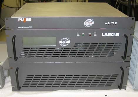
BZ5MXI501U
Nov 22, 2010Digital Television Broadcast Translator
Equipment Class
TBC - Licensed Broadcast Station TransmitterBZ5DTT250M
Jul 22, 2010Digital Television Broadcast Translator
Equipment Class
TBC - Licensed Broadcast Station Transmitter