BZ5MX30VXTranslator
Larcan Inc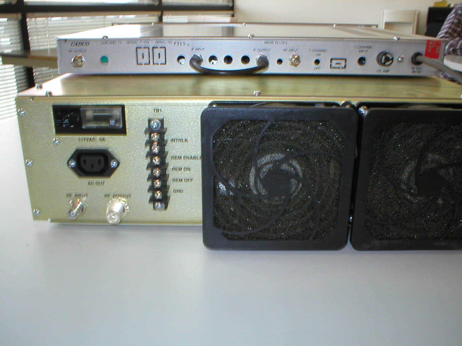
Click to zoom
Application Details
- Equipment Class
- TBC - Licensed Broadcast Station Transmitter
- Date of Grant
- Jun 11, 2003
- Application Purpose
- Original Equipment
- Date of Application
- Apr 29, 2003
- Equipment Note
- Translator
- Frequency Range
- 54.00000000 - 216.00000000
- Company
- Larcan Inc
- Country
- Canada
Documents & Files
Document Text
Text extracted from the exhibit documents filed with the FCC. Open a document above to read the original.
Users Manual
PUBLICATION TSM 20-332 TECHNICAL MANUAL 30 WATT VHF AMPLIFIER FOR MX30V SERIES TV TRANSMITTER/TRANSLATOR LARCAN INC. 228 AMBASSADOR DRIVE MISSISSAUGA, ONTARIO CANADA L5T 2J2 PHONE: (905) 564-9222 FAX: (905) 564-9244 Rev 0: November 26, 1998 MX30V series - 30 Watt VHF AMPLIFIER Section Title Page NOTICES, ETC.................................................................3 SAFETY AND HEALTH WARNINGS.....................................4&5 GENERAL SERVICE INFORMATION 1) Parts Lists Explained...................................5 2) Interpreting LARCAN Drawing Numbers.....................5 3) The LARCAN Assembly Prefix Numbering System.............6 4) List of Prefix Numbers for the 10 W Transmitter.........7 5) Production Changes......................................7 INTRODUCTION.....................................................8 GENERAL DESCRIPTION..............................................8 SPECIFICATIONS..................................................10 ABOUT THIS MANUAL...............................................11 PUBLICATIONS LIST for MX30V series VHF Amplifier: PUB98-29 Installation: 1. General Information..............................29-1 2. Grounding and Ground Loops.......................29-2 3. Lightning and other Transient Protection.........29-4 4. Power Wiring.....................................29-9 5. Ventilation and Air Conditioning................29-10 6. Fire Protection.................................29-11 7. Unpacking.......................................29-12 8. Transmitter External Interlock Connections......29-12 9. On Site: First Time Startup.....................29-13 PUB98-30 Amplifier Chassis (Prefix 1): 1. Amplifier Chassis Description....................30-1 Comment: don't forget to set the footer date stamp to release date,and make sure that any revisions have the date stamp the same date as the revision. MX30V series - 30 Watt VHF AMPLIFIER PUB98-31 RF Output System: Filter and Directional Coupler (Prefixes 6 & 7): 1. HB Helical Resonator Bandpass Filter Description........31-1 2. HB Low Power Bandpass Filter Description................31-3 3. LB Low Pass & Notch Filter Description..................31-4 4. RF Directional Coupler Description......................31-5 PUB98-32 RF Power Amplifier (Prefix 2): 1. Introduction and General Description....................32-1 2. Preamplifier Circuit Board Assembly.....................32-2 3. RF Power Amplifier......................................32-2 PUB98-33 Amplifier Control Board & Metering Panel (Prefix 4): 1. Control Board & Metering Panel Description..............33-1 2. Amplifier Control Circuit Board Description.............33-2 PUB98-34 Transmitter Output RF Metering Detector Board (Prefix 5): 1. RF Metering & AGC Board Description.....................34-1 2. RF Metering Board Test and Calibration..................34-2 PUB98-34a Pin Attenuator Board (Prefix 9): 1. Pin Attenuator Board Description.......................34a-1 2. Pin Attenuator Board Setup.............................34a-1 INTRODUCTION This manual describes the LARCAN 30 watt VHF amplifier designed for NTSC channels 2 through 13. Models 40D2232G1 is for channels 7 through 13, 40D2232G2 for channels 2, 3, and 4, and model 40D2232G3 is for channels 5 and 6. These amplifiers are used in the LARCAN-USA MX30V series transmitters and translators. LARCAN all-solid-state 30 W VHF amplifier were designed to operate conservatively at 30 W peak sync visual RF power and 3 W average aural single carrier RF power, with superb performance, reliability and operating economy. This amplifier accepts an on-channel internally diplexed (in a 10:1 ratio vis to aur) composite driving signal of about 1mW peak visual RF, as input to its RF chain. The 30 W amplifier and channel processor chassis' are designed to fit in a single 19" customer-provided cabinet rack, and require 7" (4RU) of vertical panel space for a complete transmitter or translator system. Alternatively, a 19" customer-provided tabletop cabinet could be substituted if the site requires it. The RF amplifier heatsink has its own integral cooling fan, and other sub- assemblies are convection cooled. The simplicity of design, the deployment of all modular and other subassemblies, and the use of standard readily available components, also enhances serviceability. Peak forward and reflected power are displayed on an analog percent power meter located on the front panel of the unit. AMPLIFIER CHAIN The internally diplexed composite RF output of the channel processor is fed to a conservatively designed broadband solid-state amplifier. This amplifier requires no tuning or adjustment. Simplicity of operation, reduced maintenance costs and increased reliability are a few of the major benefits derived from this amplifier. The amplifier chain consists of two stages of amplification for low band and three stages for high band. For amplifiers having somewhat more gain than usual, and especially for 10 watt output applications, the exciter driving the preamplifier may be padded down with an inline attenuator to avoid overdrive to the preamplifier, because exciters generally perform better at higher output levels. The preamplifier uses high gain, broadband, integrated circuit amplifier(s) operating class A. This preamplifier has two stages in high band models, while a single stage suffices for low band. The preamplifier uses the same circuit board that is an integral part of the "phase quadrature control" that is a required part of paralleled amplifier configurations. The 30 W transmitter uses a single RF chain, consequently quadrature phasing is not needed nor used, but some low cost components for it may remain in place on the board. Removal entails far greater overall expense than simply leaving them in place. The PA stage consists of a pair of push-pull FETs in a single case, operating in class AB as a linear amplifier. This amplifier is capable of more than 50 watts RF output when driven by the preampli…
Text truncated - open the document above for the full version.
Operational Description
BZ5MX30VX Application for FCC Certification Heterodyne Processor Input 30 Watt VHF Translator GENERAL DESCRIPTION This application requests authorization for video/audio input to our 30W VHF Translator, BZ5MX30VX. The Translator will be driven directly by a color television demodulator. The intended use of the MX30VX is to rebroadcast a television translator relay station of other legal source of video and audio. The MX30VX is a solid-state Translator designed to operate at 30W peak sync visual RF power and 3W average aural single carrier RF power. The MX30VX Translator accepts an on-channel internally diplexed composition driving signal of 10mW peak visual RF, as input to its RF chain. The MX30VX Translator is self-contained single 19” cabinet with an integral cooling fan. The simplicity of design, the employment of modular subassemblies, and the use of standard, readily available, components also enhance serviceability. The unit tested specifically for this application was operated on Channel 11. This channel was chosen to provide protection to and from existing radio services, and to facilitate the measurement of possible spurious products conducted or radiated from the 30W VHF Translator. The input signals used in the equipment application tests were generated by a color bar generator driving a Cadco Heterodyne Processor which is typically the unit used. However, due to varying customer requirements, other demodulators are available upon customer request. The published specifications on any demodulator used in this equipment will meet or exceed FCC specifications. The Cadco Heterodyne Processor of this translator will accept audio from the television relay station. Frequency spacing, deviation, and other characteristics including distortion are therefore determined solely by the originating television station. It is anticipated that the translator will be driven directly by the demodulator output of an FM microwave repeater. No provision is made for tampering with or adjusting the composite video or audio signal except for depth of video modulation. Therefore, all aspects of the input video signal are determined solely by the originating television station. The MX30VX meets all the requirements for unattended operation. A description of the automatic control circuitry can be found in the user’s manual. Station identification requirements will be supplied by the originating station. Wiring, shielding and construction are in accordance with accepted principles of good engineering practice. The translator’s construction is such that all hazardous components are enclosed of protected against accidental contact by operating personnel.
Parts List/Tune Up Info
BZ5MX30VX Application for FCC Certification Heterodyne Processor Input 30 Watt VHF Translator ACTIVE DEVICES AND FUNCTION LIST DEVICE TYPE FUNCTION MODULE: Phase Shifter #10A1354G4 (High Band) U2 MHW6185 Hybrid Amplifier U3 MC7824CT +24V Voltage Regulator U4 MWA330 RF Amplifier MODULE: Phase Shifter #10A1354G5 (Low Band) U2 MHW6185 Hybrid Amplifier U3 MC7824CT +24V Voltage Regulator MODULE: Power Amplifier #30C1054G3 Q1 SRF3943-2 RF Power MODULE: Power Metering PCB #20B1235G7 Q1, Q2 MPS8598 Amplifier U2, U3, U4 LM358N Op Amp MODULE: Control PCB #30C1829G2 U3 ILQ1 Optical Isolator Contents: Sec Topic Page 1 RF Metering Board Description.................................34-1 2 RF Metering Board Test and Calibration........................34-3 List of Figures: Fig Title Drawing Reference 1 Metering Board Assembly..................................20B1235G7 2 Metering Board Schematic................................20B1245sh2 1. RF Metering Board 20B1235G7: Figures 1 and 2. The function of this board is to monitor the forward & reflected power. Except for their functions and input names, metering boards have identical RF detectors. For this reason, Detector #1 for "Forward" will be described, and #2 for "Reflected" will be referenced by its component numbers inside parentheses ( ). a) RF Detectors: The #1 Forward (#2 Reflected) RF power sample is applied to J1 (J2) and is terminated by R2 (R4). A small amount of forward bias is applied to CR1 (CR2) via R1 and R5 (R3, R6) to overcome the threshold voltage of the diode and enhance its detection linearity at low signal levels. The opposing connection of CR1 (CR2) diode junction and Q1 (Q2) emitter-base junction provides temperature compensation. Q1 (Q2) buffer amplifier provides a low impedance source to drive the trap C3, C4, and L1 (C5, C6, L2), through R9 (R10). This trap is broadly resonant to 4.3 MHz, and significantly attenuates 3.58 MHz NTSC color subcarrier as well as any 4.5 MHz intercarrier that may be generated in CR1 or CR2 due to the presence of visual and aural RF signals together in the system. Removal of these subcarrier components before the signal is peak detected, enables the circuit to be responsive to sync peak power only (for visual) or just CW (aural) power, and relatively immune to undesired carriers. CR3 (CR4) is a peak detector with a time constant set by C7 and R11 (C8, R12). The signal from this peak detector is fed to op-amp U1 (U2) pin 5 and . The gain of this stage is 0.5x (0.5x), and its output on pin 7 feeds the meter which is located on the front panel of the amplifier. U1 (U2) output pin 7 zero-offset voltage is controlled by R18 (R20). This pot should be set with no RF input, so that while you watch the voltage on TP1 (TP2) as you are setting the pot, you will observe the decrease of the voltage towards zero. When it ceases decreasing, stop adjusting. Expect about 50 mV offset Comment: The footer date stamp must agree with the revision date. voltage when the op-amp output is almost touching ground. If the pot is turned beyond this point, the output stage of the op-amp will be driven into saturation thus unable to respond to low power levels. 1. RF Metering Board 20B1235G7: Figures 1 and 2. (continued). The output of U1-7 (U2-7) drives the RF power meter through R32 (R30) which set the meter deflection with a known RF signal. U1-7 (U2-7) drives. Forward calibration is done with full rated power and a forward RF sample from the directional coupler applied to J1. R32 is adjusted for a 100% reading on the forward power meter position. For Reflected calibration, the same forward RF sample is then applied to J2, R30 is set for a 100% reading on the Reflected Power meter. 2. RF Metering Board Test and Calibration: (Refer also to the Pin Attenuator section of this manual) a) Forward Power Meter Calibration - Zero Adjust With no RF input connected, measure the DC voltage at U1-7 (or TP1) and adjust R18 until the output voltage at U1-7 (TP1) drops to a minimum, approximately 10 to 50 mVDC. A DC coupled scope will make the adjustment easier to see; the objective is to place the U1 output as near the op-amp ground rail as possible without the op-amp going into saturation. Turning the pot farther will decrease the sensitivity of the system for small signals. Once this minimum voltage has been reached, do not re-adjust R18. b) Reflected Power Meter Calibration - Zero Adjust With no RF input connected, measure the DC voltage at U2-7 (or TP2) and adjust R20 for a minimum, which should be approximately 50 mVDC. Once this minimum voltage has been reached, do not re-adjust R20. This adjustment is done in precisely the same way as in step a) above. c) Forward Power calibration Set the exciter RF output for the transmitter to run at its operating power. Adjust R32 for a forward power meter reading of 100%. NOTE: Before proceeding to the next step, ensure that the Pin Attenuator Board has been setup according to the procedure on the Pin Attenuator Board section of this manual (see page 34a-1). d) Reflected Power calibration 1. Temporarily defeat the VSWR cutback protection (if it's been initially setup) by adjusting R36 fully clocwise (CW). With the transmitter still at "full power", disconnect the RF input cable from J1 and connect it instead to the reflected power input J2. Switch to position `RFL' and adjust R30 so that the reflected power reads 100. This now corresponds to a reflected power of 100%. 2. Enable the VSWR cutback by turning R36 counter clockwise until the meter indicates 10% output. This means that in severe VSWR conditions such as in an open circuit, the amplifier will automatically cuts back to 10% thus protecting itself. 3. Replace the cables in their proper connections. RFL meter reading should be nill and the FWD meter reading should be back to 100%. If the FWD reading is much less than 100%, R36 was probably overadjusted.
Test Report
BZ5MX30VX Application for FCC Certification Heterodyne Processor Input 30 Watt VHF Translator FREQUENCY DRIFT VS. TEMPERATURE P379 CHANNEL PROCESSOR MEASURED DEGREES C LO FREQUENCY(Hz) DEVIATION(Hz) DEVIATION(%) -30BC 181,251,502 +3525 +0.001945 -20BC 181,250,604 +2909 +0.001605 -10BC 181,249,853 +2158 +0.001191 0BC 181,248,650 +955 +0.000527 +10BC 181,248,200 +505 +0.000279 +20BC 181,247,958 +263 +0.000145 +25BC 181,247,695 0 0(REF) +30BC 181,247,268 -427 -0.000236 +40BC 181,246,883 -812 -0.000448 +50BC 181,246,502 -1193 -0.000658 FCC Specification: Frequency Stability of Carrier +0.02%. BZ5MX30VX Application for FCC Certification Heterodyne Processor Input 30 Watt VHF Translator FREQUENCY DRIFT VS TEMPERATURE BLOCK DIAGRAM Test Equipment List Power Supply - Hewlett Packard HP6012A S/N 2329A-02181 Frequency Counter - Hewlett Packard HP5334B S/N 2937A05503 Thermometer - Fluke 77/80T-150U Thermostatically Controlled Temperature Chamber - Associated Variac Power Supply Frequency Counter Temperature Chamber Thermometer LO Processor
Test Report
BZ5MX30VX Application for FCC Certification Heterodyne Processor Input 30 Watt VHF Translator OUTPUT STABILITY OF AGC INPUT LEVEL(dB) RELATIVE OUTPUT POWER dB = 100% Output Power -20 -0.1 -15 -0.1 -10 -0.1 -5 0 500uV = 0dB 0.0 (Ref) +5 0 +10 0 +15 0 +20 -0.1 -20 -0.1 -15 0 -10 0 -5 0 1000uV = 0 dB 0.0 (Ref) +5 0 +10 0 +15 0 +20 -0.1 -20 0 -10 0 -5 0 5000uV = 0 dB 0.0 (Ref) +5 0 +10 0 +15 -0.1 +20 -0.1
Test Report
BZ5MX30VX Application for FCC Certification Heterodyne Processor Input 30 Watt VHF Translator POWER MEASUREMENTS Power requirements for the 30 Watt VHF Translator were determined as follows: 1. The translator's visual power meter measures the peak visual power by reading the average levels of a detected sample of the output. The meter is calibrated by multiplying the above visual power reading by 168%. The visual metering circuitry has a negligible response to the aural power due to the large (>10MHz) detector bandwidth. When the detector bandwidth is this large, the detector does not peak detect the intercarrier beat product. 2. The aural power is measured by reading the peak level of the detected 4.5MHz intercarrier product. The level of this product has a direct correspondence to the aural power and is independent of the visual power as long as the peak visual power exceeds the aural power. SUPPLY CURRENT SUPPLY CURRENT MEASURED MEASURED TO O/P DEVICES TO O/P DEVICES VISUAL PWR AURAL PWR VISUAL ONLY VISUAL & AURAL NOTE 1 NOTE 2 NOTE 3 NOTE 3 18 Watts 3 Watts 3.0 Amps 3.0 Amps Note 1: Measured on the Bird Model 43 Wattmeter with the visual carrier modulated by the standard synchronizing signal at 75% of peak amplitude and the aural carrier disabled. Note 2: Measured on the Bird Model 43 Wattmeter with the visual carrier disabled. Note 3: The voltage across the output devices on all models in +24 volts. The output devices are operated Class 'A'.
Test Report
BZ5MX30VX Application for FCC Certification Heterodyne Processor Input 30 Watt VHF Translator OVERALL GROUP DELAY FREQUENCY(MHz) OVERALL DELAY(nS) 0.20 0(Ref) 0.40 -10 0.60 +30 0.80 -20 1.00 +30 1.20 -5 1.40 0 1.60 0 1.80 -35 2.00 -20 2.20 -10 2.40 -60 2.60 +10 2.80 -10 3.00 -50 3.20 -80 3.40 -120 3.58 -160 3.80 -200 4.00 -320 4.18 -350
Test Report
BZ5MX30VX Application for FCC Certification Heterodyne Processor Input 30 Watt VHF Translator TEST BLOCK DIAGRAM Test Equipment List Modulator - Catel ATM-1600 S/N 304315 Video Generator - Tektronix 1910 S/N B010219 Sweep Generator - Hewlett Packard HP8647A S/N 3247A00653 Attenuator - Mini Circuits - ZAY-2 S/N 18895 Translator - MX30VX S/N 25502-4 Heterodyne Processor - Cadco P379 S/N E2425 Power Meter - Bird Model 43 S/N 124420 Directional Coupler - Dielectric 8340-200 S/N 4956 Load - Dielectric 8340-200 S/N 4956 Oscilloscope - Tektronix VM700A S/N B040433 Detector - Tektronix TEK1450-1 S/N B010838 Spectrum Analyzer - Hewlett Packard HP8591E S/N 3325A01739 Dipole Antenna Cut to Frequency (for field strength measurements only) Power Meter Load Modulator Attenuator Translator w/Processor Directional Coupler Video Generator Sweep Generator Detector Spectrum Analyzer Dipole Ant Oscilloscope
Test Setup Photos
BZ5MX30VX Application for FCC Certification Heterodyne Processor Input 30 Watt VHF Translator TEST BLOCK DIAGRAM Test Equipment List Translator – MX30VX S/N 25502-4 Heterodyne Processor – Cadco P379 S/N E2425 Power Meter – Bird Model 43 S/N 124420 Directional Coupler – Dielectric 8340-200 S/N 4956 Load – Dielectric 8340-200 S/N 4956 Oscilloscope – Tektronix VM700A S/N B040433 Detector – Tektronix TEK1450-1 S/N B010838 Spectrum Analyzer – Hewlett Packard HP8591E S/N 3325A01739 Dipole Antenna Cut to Frequency (for field strength measurements only) Translator w/Processor Power Meter Directional Coupler Load Detector Spectrum Analyzer Oscilloscope Dipole Ant
Contact Information
Applicant
John E. Tremblay(Engineering, Vice President)
Technical Contact
Larcan Inc.John E Tremblay
[email protected](905) 564.9222
228 Ambassador Drive · Mississauga, Ontario · Canada
Non-Technical Contact
Larcan USA Inc.Paula A Cooper
[email protected](303) 665.8000
Technical Specifications
| # | Rule Parts | Frequency Range | Power Output | Emission | Tolerance |
|---|---|---|---|---|---|
| 2 | 74 | 54 MHz - 216 MHz | 3 W | 250KF3E | 0.002 % |
Other Applications from Larcan Inc
BZ5DTR10SC
Jun 16, 2014Digital Television Translator
Equipment Class
TBC - Licensed Broadcast Station Transmitter
BZ5MXI1503U
Aug 04, 2013Television Broadcast Translator
Equipment Class
TBC - Licensed Broadcast Station Transmitter
BZ5MXI1002U
Jul 11, 2012Digital Television Translator
Equipment Class
TBC - Licensed Broadcast Station Transmitter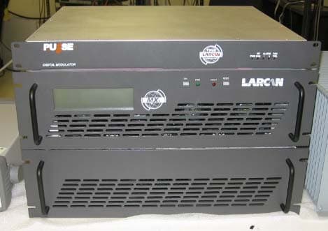
BZ5MXI501U
Nov 22, 2010Digital Television Broadcast Translator
Equipment Class
TBC - Licensed Broadcast Station TransmitterBZ5DTT250M
Jul 22, 2010Digital Television Broadcast Translator
Equipment Class
TBC - Licensed Broadcast Station Transmitter