BZ5MXI005UDigital Television Broadcast Translator
Larcan IncApplication Details
- Equipment Class
- TBC - Licensed Broadcast Station Transmitter
- Date of Grant
- Feb 18, 2010
- Application Purpose
- Original Equipment
- Date of Application
- Jan 21, 2010
- Equipment Note
- Digital Television Broadcast Translator
- Frequency Range
- 614.00000000 - 806.00000000
- Company
- Larcan Inc
- Country
- Canada
Documents & Files
Document Text
Text extracted from the exhibit documents filed with the FCC. Open a document above to read the original.
Users Manual
MXi005U AMPLIFIER TECHNICAL SERVICE MANUAL LARCAN INC. 228 AMBASSADOR DRIVE MISSISSAUGA, ONTARIO CANADA L5T 2J2 PHONE: (905) 564-9222 FAX: (905) 564-9244 EMAIL: [email protected] PUB06-76 Rev 2 July 18, 2007 MXi005U OPERATIONS AND MAINTENANCE CONTENTS 1 MXi005U AMPLIFIER .....................................................................................................................................................1 2 MXi CONTROLLER........................................................................................................................................................2 2.1 MXi005U CONTROL BOARD ASSEMBLY AND JUMPER SETTINGS.................................................................................2 2.2 REMOTE CONTROLS AND THE MXi005U FRONT PANEL ON/OFF BUTTON..................................................................4 2.3 EXTERNAL REMOTE CONTROL CONNECTIONS..............................................................................................................4 2.3.1 Remote Command Inputs .....................................................................................................................................4 2.3.2 Remote Telemetry Outputs ...................................................................................................................................5 2.3.3 Remote Status Outputs .........................................................................................................................................5 2.3.4 External1 Interlock ..............................................................................................................................................6 2.4 EXTERNAL TRANSMITTER INTERLOCK.........................................................................................................................6 3 AMPLIFIER INSTALLATION AND STARTUP ..........................................................................................................8 3.1 BEFORE APPLYING AC TO THE UNIT............................................................................................................................8 3.2 APPLYING AC TO THE UNIT..........................................................................................................................................8 3.3 BEFORE TURNING THE AMPLIFIER ON .........................................................................................................................9 3.4 AMPLIFIER ON SEQUENCE............................................................................................................................................9 3.4.1 Turning ON MXi Amplifier..................................................................................................................................9 4 TEST AND TROUBLESHOOTING .............................................................................................................................10 4.1 BENCH TEST PROCEDURES.........................................................................................................................................10 4.1.1 Front-End Module Bench Test Procedure .........................................................................................................10 4.1.2 IPA1 Bench Test Procedure ...............................................................................................................................10 4.1.3 Pallet 21B1751 Bench Test Procedure ..............................................................................................................10 4.2 BASIC TROUBLESHOOTING TECHNIQUES....................................................................................................................11 4.2.1 Amplifier Completely OFF.................................................................................................................................11 4.2.2 No RF Output.....................................................................................................................................................11 4.2.3 Output Reduced to 25% .....................................................................................................................................11 5 MAINTENANCE.............................................................................................................................................................12 5.1 DAILY.........................................................................................................................................................................12 5.2 MONTHLY...................................................................................................................................................................12 5.3 SEMI-ANNUALLY AND ANNUALLY.............................................................................................................................12 5.4 TRANSMITTER COOLING SYSTEM...............................................................................................................................12 6 TEST EQUIPMENT SETUP..........................................................................................................................................13 7 SPECIFICATIONS .........................................................................................................................................................14 7.1 ELECTRICAL...............................................................................................................................................................14 7.2 ENVIRONMENTAL.......................................................................................................................................................14 7.3 COOLING....................................................................................................................................................................14 7.4 DIMENSIONS.......................................…
Text truncated - open the document above for the full version.
ID Label/Location Info
BZ5MXI005U Application for FCC Certification 5 Watt Digital Television Translator FCC Label/Label Location
Operational Description
BZ5MXI005U Application for FCC Certification 5 Watt Digital Television Translator Operational Description: This application requests certification for a 5 Watt Digital Television Translator. The intended use of this digital translator is to rebroadcast a television relay station or other legal source of ATSC digital television signal. The MXi005U is a solid state digital regenerative translator designed to receive over-the- air ATSC signals, converting the RF signal to baseband digital format, processing the signal to eliminate noise, and then re-modulating, converting to the new broadcast channel, amplifying and filtering the signal before it is applied to the transmit antenna. The receive section of the translator and the output modulation format conform with FCC Part 73.682(d), ATSC Digital Television Standards. The MXi005U consists of three components: a 1RU RegenT Transcoder unit which receives processes and re-modulates the signal, a 2 RU RF amplifier, and an output filter. The power supply and amplifier are integral. The translator meets all FCC requirements for both the simple emissions mask and the stringent emissions mask. The output filter along with additional filtering within the amplifier provide more than 85dB of attenuation within the GPS Frequency bands (1164- 1240 MHz and 1559-1610 MHz). Note that since these products are frequency agile in that they can be field tuned for different channels within the UHF television band, each unit has this filtering included, regardless of the channel. Testing results shown in this document were conducted on channel 27 (551 MHz center frequency) with the exception of the frequency stability testing which was conducted on channel 34 (650MHz). These test results are representative of performance on any channel in the UHF broadcast spectrum. Wiring, shielding and construction are in accordance with accepted principles of good engineering practice. The translator’s construction is such that all hazardous components are enclosed or protected against accidental contact by operating personnel.
Schematics
MXD5U OPERATIONS AND MAINTENANCE Figure 9 - Front End Amplifier, MXD5U PUB09-03 Rev 0 April 16, 2009 09-03-16 MXD5U Operations and Maintenance MXD5U OPERATIONS AND MAINTENANCE Figure 10 - IPA Assembly, MXD5U PUB09-03 Rev 0 April 16, 2009 09-03-17 MXD5U Operations and Maintenance MXD5U OPERATIONS AND MAINTENANCE PUB09-03 Rev 0 April 16, 2009 09-03-18 MXD5U Operations and Maintenance Figure 11 - Amplifier Pallet, MXD5U MXD5U OPERATIONS AND MAINTENANCE PUB09-03 Rev 0 16 April, 2009 09-13-19 MXD5U Operations and Maintenance Figure 12 MXD5U Control Board Assembly MXD5U OPERATIONS AND MAINTENANCE NOTES PUB09-03 Rev 0 16 April, 2009 MXD5U Operations and Maintenance
Test Report
BZ5MXI005U Application for FCC Certification 5 Watt Digital Television Translator Cabinet Radiation BZ5MXI005U Application for FCC Certification 5 Watt Digital Television Translator Cabinet Radiation
Test Report
BZ5MXI005U Application for FCC Certification 5 Watt Digital Television Translator Attenuation Characteristics
Test Report
BZ5MXI005U Application for FCC Certification 5 Watt Digital Television Translator Spurious Emissions (Simple Mask) BZ5MXI005U Application for FCC Certification 5 Watt Digital Television Translator Spurious Emissions (Stringent Mask) BZ5MXI005U Application for FCC Certification 5 Watt Digital Television Translator Spurious Emissions
Test Report
BZ5MXI005U Application for FCC Certification 5 Watt Digital Television Translator Frequency Drift versus Temperature Readings Calculation Pilot Frequency Deviation% from ref. Temp (°C) VAC= 102120138(Hz) -30 65030735565030740065030731857040.00087712 -20 65031066265031066265031066223600.00036290 -10 6503125896503125896503125894330.00006658 0 6503133596503133596503133593370.00005182 10 65031407265031407265031407010500.00016146 20 65031302265031302265031302200.00000000 30 65031175765031176765031175012720.00019560 40 65031071165031075065031072123110.00035537 50 65031003765031003765031003729850.00045901 60 65031077565031077565031077522470.00034553 Test Setup for Frequency Stability measurements. Test Equipment List: Thermostatically controlled Temperature Chamber – Cincinnati Sub-Zero HP 8594E Spectrum Analyzer S/N: 3303A00399
Test Report
BZ5MXI005U Application for FCC Certification 5 Watt Digital Television Translator Digital Signal: Eye Diagram/Signal to Noise Ratio/Error Vector Magnitude BZ5MXI005U Application for FCC Certification 5 Watt Digital Television Translator Digital Signal: Group Delay/Frequency Response
Test Setup Photos
BZ5MXI005U Application for FCC Certification 5 Watt Digital Television Translator Test Setup Photo: Block Diagram of Test Setup: Test Equipment: Instrument Make/Model Serial # Last Cal. Date. Spectrum Analyzer HP8594E 3303A00399 Dec. 3, 2003 Signal Analyzer Tektronix RFA300 B010126 Feb. 6, 2003 RF Network Analyzer Agilent 8712ET US40371604 Mar. 6, 2000
Contact Information
Applicant
John E. Tremblay(Engineering, Vice President)
Technical Contact
LARCAN Inc.John Tremblay
[email protected]905 564 9222
228 Ambassador Drive · Mississauga, Ontario · Canada
Non-Technical Contact
LARCAN Inc.John Tremblay
[email protected]905 564 9222
Technical Specifications
| # | Rule Parts | Frequency Range | Power Output | Emission | Tolerance |
|---|---|---|---|---|---|
| 2 | 74 | 614 MHz - 806 MHz | 5 W | 6M00K1D | 0.002 % |
Other Applications from Larcan Inc
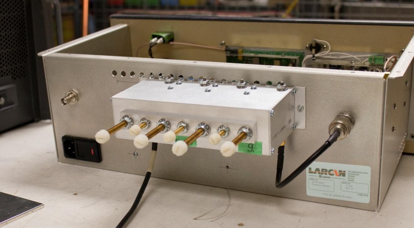
BZ5DTR10SC
Jun 16, 2014Digital Television Translator
Equipment Class
TBC - Licensed Broadcast Station Transmitter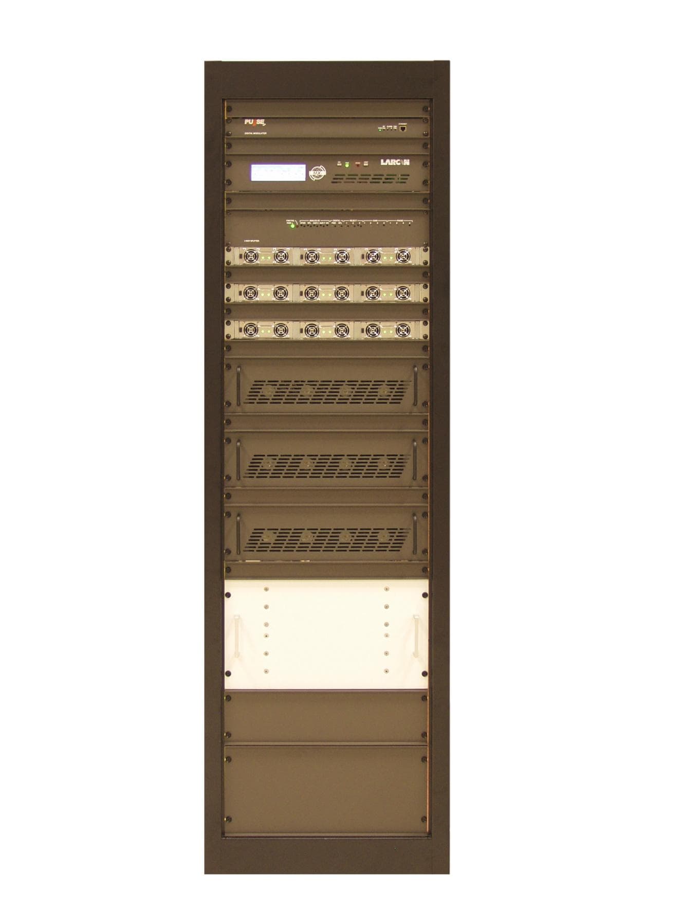
BZ5MXI1503U
Aug 04, 2013Television Broadcast Translator
Equipment Class
TBC - Licensed Broadcast Station Transmitter
BZ5MXI1002U
Jul 11, 2012Digital Television Translator
Equipment Class
TBC - Licensed Broadcast Station Transmitter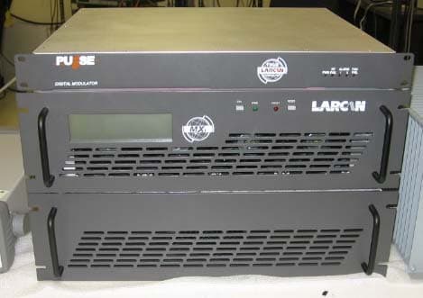
BZ5MXI501U
Nov 22, 2010Digital Television Broadcast Translator
Equipment Class
TBC - Licensed Broadcast Station TransmitterBZ5DTT250M
Jul 22, 2010Digital Television Broadcast Translator
Equipment Class
TBC - Licensed Broadcast Station Transmitter