BZ5MXI101VDigital Television Broadcast Translator
Larcan Inc
Click to zoom
Application Details
- Equipment Class
- TBC - Licensed Broadcast Station Transmitter
- Date of Grant
- Feb 18, 2010
- Application Purpose
- Original Equipment
- Date of Application
- Jan 19, 2010
- Equipment Note
- Digital Television Broadcast Translator
- Frequency Range
- 174.00000000 - 216.00000000
- Company
- Larcan Inc
- Country
- Canada
Documents & Files
Document Text
Text extracted from the exhibit documents filed with the FCC. Open a document above to read the original.
Users Manual
TSM21Q-365 MXi101V AMPLIFIER TECHNICAL SERVICE MANUAL LARCAN INC. 228 AMBASSADOR DRIVE MISSISSAUGA, ONTARIO CANADA L5T 2J2 PHONE: (905) 564-9222 FAX: (905) 564-9244 EMAIL: [email protected] TSM21Q-365 Rev 0 July 17, 2009 1 MXI101V TECHNICAL SERVICE MANUAL CONTENTS TSM20-365 MXi201U TECHNICAL SERVICE MANUAL 1 MXi201U AMPLIFIER–INTRODUCTION ..................................................................................................................3 2 SAFETY NOTICES..........................................................................................................................................................4 2.1 BERYLLIUM OXIDE WARNING......................................................................................................................................4 2.2 OTHER TOXIC MATERIALS...........................................................................................................................................4 2.3 DANGEROUS VOLTAGES...............................................................................................................................................4 2.3.1 Switch to Safety ....................................................................................................................................................5 3 LARCAN PARTS, ASSEMBLIES, ASSEMBLY DRAWINGS AND SCHEMATIC NUMBERS ...........................7 3.1 VENDOR STANDARD PART NUMBERS...........................................................................................................................7 3.2 LARCAN NUMBERS FOR PARTS, ASSEMBLIES AND DOCUMENTATION.......................................................................7 3.3 LEADED RESISTORS......................................................................................................................................................8 3.4 SURFACE MOUNT RESISTORS 1/4W AND LESS.............................................................................................................8 3.5 SURFACE MOUNT CAPACITORS....................................................................................................................................9 3.6 PARTS LISTS.................................................................................................................................................................9 3.6.1 Production Changes.............................................................................................................................................9 FIGURES FIGURE 1 MXI AMPLIFIER HEATSINK ASSEMBLY........................................................................................................................3 TSM21Q-365 Rev 0 July 17, 2009 MXi101V 2 MXI101V TECHNICAL SERVICE MANUAL 1 MXI101V AMPLIFIER–INTRODUCTION This Technical Service Manual contains publications (PUBs) describing the technical details of the MXi101V amplifier, as well as the overall operating instructions, including the bench test procedures of the amplifier stages incorporated in this unit. It also covers the transmitter’s start-up operation, and troubleshooting, as well as basic transmitter maintenance guidelines. The RF section of the MXi101V Amplifier consists of a heatsink assembly that includes three cascaded broadband amplifier modules and a directional coupler. Figure 1 shows the layout of an MXi201 assembly. The MXi101V utilizes one of these output amplifiers only. Figure 1 MXi Amplifier Heatsink Assembly Also mounted on the heatsink is a thermal switch that protects the amplifier from over temperature conditions. TSM21Q-365 Rev 0 July 17, 2009 MXi101V 3 MXI101V TECHNICAL SERVICE MANUAL 2 2.1 2.2 2.3 SAFETY NOTICES This section provides general guidance and information for the operation, maintenance, and service personnel who are familiar with the hazards of working with high-powered electronic circuits. This manual does not detail all of the safety precautions which should be observed when servicing this or any other electronic equipment. Service by inadequately trained or inexperienced personnel can result in personal injury or death and/or damage to the equipment. Important: All personnel concerned with the servicing of this equipment should be thoroughly familiar with standard first aid procedures for the treatment of electrical burns and shock, including cardio-pulmonary resuscitation (CPR). Use the “buddy” system, with one person performing the actual service and a colleague observing. The observer must be familiar with the work being performed and within sight and sound of the person doing the work. The observer should not be engaged in any other work or be otherwise distracted; he must be available instantly in case of accident. Always have the observer with you when you work on the transmitter. BERYLLIUM OXIDE WARNING Internal thermal management in certain RF devices in this equipment is accomplished through the use of Beryllium Oxide ceramic material. Do not break open any RF power transistors, or otherwise dismantle them. Beryllium Oxide is a hard white ceramic used as insulation for heatsinking of RF power semiconductors. Beryllium Oxide is a poison. In case of accidental breakage of devices, do not inhale the resulting beryllium dust and avoid getting beryllium dust in your mouth. Do not let beryllium into your blood stream through cuts or open wounds. Seek immediate medical attention if the dust enters your body in any manner. Avoid cuts by wearing gloves while picking up the broken pieces. Be careful – do not inhale dust while replacing or emptying vacuum cleaner filter bags and wash your hands thoroughly afterward. Wash your hands thoroughly after replacing RF power devices. Dispose of defective RF power devices only through approved toxic waste facilities. Wear gloves when picking up the pieces. Wash your hands thoroughly after replacing devices. Dispose of defective devices only through approved toxic waste facilities. When cleaning up after an accidental bre…
Text truncated - open the document above for the full version.
External Photos
BZ5MXI101V Application for FCC Certification 30 Watt Digital Television Translator Exterior Photo
ID Label/Location Info
BZ5MXI101V Application for FCC Certification 30 Watt Digital Television Translator FCC Label/Label Location
Internal Photos
BZ5MXI101V Application for FCC Certification 30 Watt Digital Television Translator Interior Photo of RF Amplifier
Schematics
POWER AMPLIFIER HEATSINK ASSEMBLY PUB09Q-001 Rev 0 5 June 2009 Figure 2 10A1453 High Band Preamplifier Assembly sht10 Rev Figure 3 10A1453 High Band Preamplifier Schematic sht10 Rev1 POWER AMPLIFIER HEATSINK ASSEMBLY PUB09Q-001 Rev 0 9 June 2009 Figure 7 Input Board Assembly 30C1003 rev 8.3 POWER AMPLIFIER HEATSINK ASSEMBLY PUB09Q-001 Rev 0 10 June 2009 Figure 8 Single Stage PA Schematic 30C1000 rev 8 POWER AMPLIFIER HEATSINK ASSEMBLY PUB09Q-001 Rev 0 11 June 2009 Figure 9 Output Board Assembly 30C1002 rev 1.1 Figure 23 MXi Controller Board Assembly Diagram 31C1897A2 sht1 Rev 2.2 Figure 24 MXi Controller Board Schematic 31C1897S1 sht1 Rev 2.3 Figure 25 MXi Controller Board Schematic 31C1897S2 sht2 Rev 2.3 Figure 26 MXi Controller Board Schematic 31C1897S3 sht3 Rev 2.3 Figure 27 MXi Controller Board Schematic 31C1897S4 sht4 Rev 2.3 Figure 28 MXi Controller Board Schematic 31C1897S5 sht5 Rev 2.3
Test Report
BZ5MXI101V Application for FCC Certification 30 Watt Digital Television Translator Attenuation Characteristics
Test Report
BZ5MXI101V Application for FCC Certification 30 Watt Digital Television Translator Frequency Drift versus Temperature READINGS CALCULATION LOCAL OSC'R FREQ (MHZ) DEVIATION FROM REF TEMP (DEG C) VAC= 102 120 138 (Hz) (%) 20 (REF) 174312212174312212174312212ref -30 1743092501743092501743092502962 0.001699 -20 1743102001743102001743102002012 0.001154 -10 1743110751743110751743110751137 0.000652 0 174311575174311575174311575637 0.000365 10 174312075174312075174312075137 0.000079 20 1743122121743122121743122120 0.000000 30 17431213517431213517431213577 0.000044 40 174312100174312100174312100112 0.000064 50 17431227517431227517431227563 0.000036 60 174312550174312550174312550338 0.000194 Test Setup for Frequency Stability measurements. Test Equipment List: Thermostatically controlled Temperature Chamber – Cincinnati Sub-Zero HP 8594E Spectrum Analyzer S/N: 3303A00399
Test Report
BZ5MXI101V Application for FCC Certification 30 Watt Digital Television Translator Power Measurements The translator’s power meter circuit uses a detected sample from a coupler on the output. An averaging detector circuit provides the DC level to drive the translator’s output level meter. The translator was connected to a test load through a calibrated directional coupler. The spectrum analyzer’s “Channel Power” function was used to measure the average power level of the signal as sampled through the directional coupler. (see Fig.) . Measured power: -1.8dBm Coupling loss: 40.6 dB Attenuator @ i/p to spectrum analyzer 6dB Power: 44.8dBm Power = 30 Watts
Test Report
BZ5MXI101V Application for FCC Certification 30 Watt Digital Television Translator Cabinet Radiation BZ5MXI101V Application for FCC Certification 30 Watt Digital Television Translator Cabinet Radiation
Test Report
BZ5MXI101V Application for FCC Certification 30 Watt Digital Television Translator Spurious Emissions (SimpleMask) BZ5MXI101V Application for FCC Certification 30 Watt Digital Television Translator Spurious Emissions (Stringent Mask) BZ5MXI101V Application for FCC Certification 30 Watt Digital Television Translator Spurious Emissions
Test Report
BZ5MXI101V Application for FCC Certification 30 Watt Digital Television Translator Digital Signal: Eye Diagram/Signal to Noise Ratio/Error Vector Magnitude BZ5MXI101V Application for FCC Certification 30 Watt Digital Television Translator Digital Signal: Group Delay/Frequency Response
Test Setup Photos
BZ5MXI101V Application for FCC Certification 30 Watt Digital Television Translator Test Setup Photo: Block Diagram of Test Setup: Test Equipment: Instrument Make/Model Serial # Last Cal. Date. Spectrum Analyzer HP8594E 3303A00399 Dec. 3, 2003 Signal Analyzer Tektronix RFA300 B010126 Feb. 6, 2003 RF Network Analyzer Agilent 8712ET US40371604 Mar. 6, 2000
Contact Information
Applicant
John E. Tremblay(Engineering, Vice President)
Technical Contact
LARCAN Inc.John Tremblay
[email protected]905 564 9222
228 Ambassador Drive · Mississauga, Ontario · Canada
Non-Technical Contact
LARCAN Inc.John Tremblay
[email protected]905 564 9222
Technical Specifications
| # | Rule Parts | Frequency Range | Power Output | Emission | Tolerance |
|---|---|---|---|---|---|
| 3 | 74 | 174 MHz - 216 MHz | 30 W | 6M00K1D | 0.02 % |
Other Applications from Larcan Inc
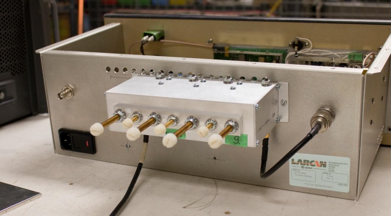
BZ5DTR10SC
Jun 16, 2014Digital Television Translator
Equipment Class
TBC - Licensed Broadcast Station Transmitter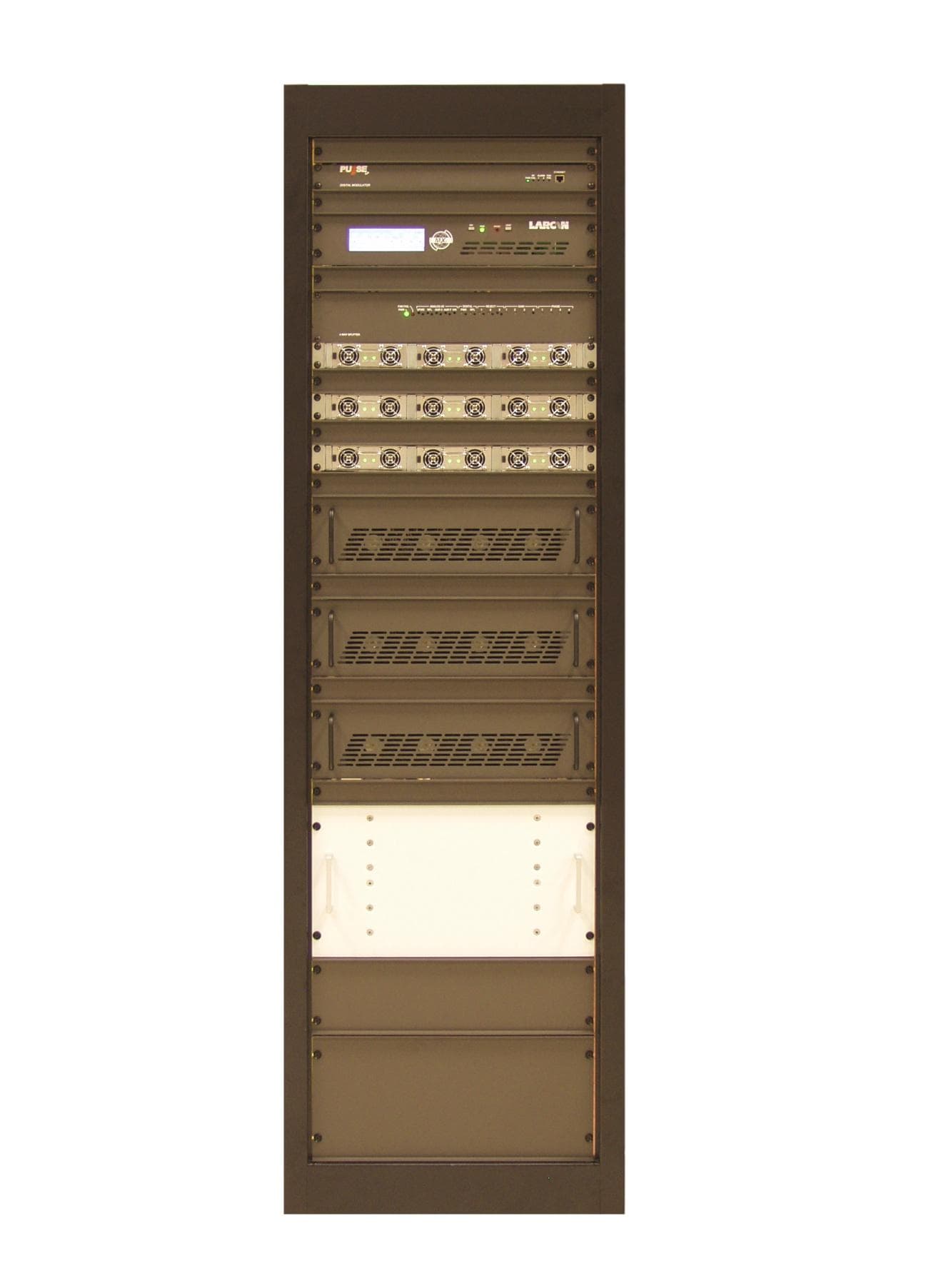
BZ5MXI1503U
Aug 04, 2013Television Broadcast Translator
Equipment Class
TBC - Licensed Broadcast Station Transmitter
BZ5MXI1002U
Jul 11, 2012Digital Television Translator
Equipment Class
TBC - Licensed Broadcast Station Transmitter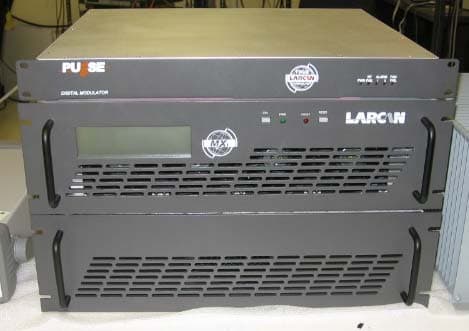
BZ5MXI501U
Nov 22, 2010Digital Television Broadcast Translator
Equipment Class
TBC - Licensed Broadcast Station TransmitterBZ5DTT250M
Jul 22, 2010Digital Television Broadcast Translator
Equipment Class
TBC - Licensed Broadcast Station Transmitter