BZ5T2500U2500 Watt UHF Transmitter
Larcan Inc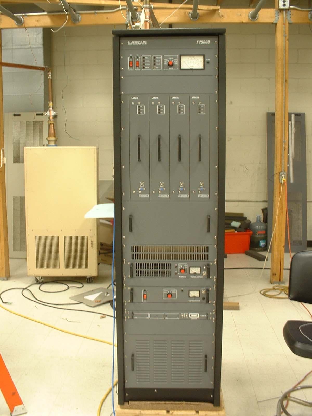
Click to zoom
Application Details
- Equipment Class
- TBC - Licensed Broadcast Station Transmitter
- Date of Grant
- Oct 18, 2005
- Application Purpose
- Original Equipment
- Date of Application
- Sep 19, 2005
- Equipment Note
- 2500 Watt UHF Transmitter
- Frequency Range
- 470.00000000 - 806.00000000
- Company
- Larcan Inc
- Country
- Canada
Documents & Files
Document Text
Text extracted from the exhibit documents filed with the FCC. Open a document above to read the original.
Users Manual
Installation - 1 - Installation - 2 - 1. Installation: 1.1. Unpacking: All the equipment is carefully inspected and tested under the company quality control. Any irregularity must be filed immediately with the carrier responsible for the transportation equipment. Any doubts, contact LARCAN Inc. before installing the equipment so that your doubt do not become a problem. 1.2. Repacking and Transportation: If it is necessary the equipment be sent back to the company or any distant place, some precaution must be considered: • Wrap the equipment with air bubble plastic. Do not let any part of the equipment exposed to protect it against any damage to the equipment painting; • Wrap the equipment with cardboard and wood pack it to protect against any impact; • Ensure that anything was left loose inside the package. Put the package stood to avoid any impact. 1.3. Installation Requirement: • Installation Site: The equipment should not be installed in places that exceeds 2000 meters of altitude; have a proper air conditioning system (if it is necessary), voltage regulator, ventilation air conducting; ensure that sufficient space around the equipment is available to permit easy access, and to enhance future ease of maintenance. It is recommended a minimum 0.5m of clearance both right and left sides, and 1.0m both front and rear of the equipment; the ceiling should have at least 3.0m of height where the blower exhaust will be installed. The place must be free of dirt, humidity and dust. • Installation Surface: For small equipment, it is recommended being installed on a table or a standard rack 19”, which it should have at least 0.3m of clearance from the wall in order to have a proper ventilation. • Power board: It is necessary a power board to organize, separate, and distribute the power supply and mainly for equipment protection. The power board is connected to the power line. Thermomagnetic disjunctor must be used in order to feed isolatedly the equipment, illumination, air conditional, blower exhaust, etc. • Voltage Regulator: A voltage regulator is used for protection against any variation and transient coming from the power line so that it will provide a better performance of your equipment. The regulator should provide at least 30% more power than the equipment consumes. It is recommended using an electronic kind regulator, microprocessed, with a perfect senoidal output, and an isolator transformer for the entrance. • Grounding: All the equipments must be connected to the main station ground system but isolated from the wall, protecting it against electrostatic discharges, lightning strikes, etc. Grounding should be 5 Ohms maximum to have an adequate protection. Ensure that the following items are connected to the main ground system: • Tower base; • Lightning rod; • Neutral wire; • Power supply ground; • All the equipment grounds such as power board, voltage regulator, etc; • Broadcast Antennas, coaxial cable and transmission line. If you have any doubts about the station ground system quality, a specialized company should be contacted. Installation - 3 - • Lightning Rod: Its use on the tower is vital and a distance of 2.0m between the last antenna and the lightning rod should be preserved. • Ambient Temperature: the ambient temperature must not exceed 25°. If it is not possible, the use of an air conditioning system should be considered. The air conditioning system should be able to keep the ambient temperature 25° maximum with full power operation of the equipment. The blower exhaust must also be installed in order to reduce the ambient temperature at the same time the power consuming of the air conditioning system reduces. • Humidity: The relative humidity of air must not exceed 80%. If it is not possible, the use of an air conditioning system will be necessary. • Antennas and cables: Pay a careful attention to the quality of coaxial cables and connectors that will be used in the system; the maximum curvature of coaxial cables must be respected; avoid loose connections. Installation - 4 - 1.4. Installation: First time start-up procedure: 1. Verify the power line supply and the voltage regulator output. For 220V or 380V you have to use a three phase voltage Y or Delta connection, respectively; 2. Connect the transmitter RF output (on the top of the transmitter) to a 50 ohm antenna or dummy load. Pay attention to the maximum curvature of the coaxial cables that are being used; 3. If the equipment has an audio and video modulator, connect the video signal to the video input jack 75 ohms and the audio signal to the audio input jack 600 ohms balanced located at the top of the transmitter; 4. If the equipment is a retransmitter, connect the Booster converter output to the IF input jack; 5. Connect the ac input at the rear of the equipment. It is recommended using a power cable feed 10.0mm; 6. Reduce the IF level from the audio and video modulator by turning its control counter- clockwise. For retransmitters, The IF level control is located at the front panel of the Channel converter. For Dual Driver Equipments, repeat the process for both Driver A and B; 7. For Dual Driver equipment, place the AUTO/MANUAL selector switch to the MANUAL position, and the PREF. A/PREF. B selector switch to the PREF. A position; 8. Disconnect all 650W amplifiers # modules; 9. Turn on the equipment by pressing the main switch at the front panel of the channel converter and at the right superior panel of the equipment. For Dual Driver turn on the main switch of channel converter “B” also; 10. Ensure that all the voltage supplies (at the Amplifier # modules connector) from each 650W amplifier module are ok; 11. By this time, only the “A” Driver will be running; 12. Check all the voltage supplies and the local oscillator of the channel converter against the equipment test list; 13. Check the Blower system. If it is rotating incorrectly check again the incoming phase voltage; 14. Turn off the equipment and reconnect all a…
Text truncated - open the document above for the full version.
Users Manual
Unit 1 – Introduction - 1 - Meridian 2.5 kW UHF Model T2500U Technical Service Manual TSM20-342 Rev. 00 August/2004 Unit 1 – Introduction - 2 - Contents Unit I Introduction 1. External Layout: Page 05 2. General technical descriptive: Page 06 3. Technical Characteristics: Page 08 4. Block Diagram: Page 09 Unit II IF Modulator 1. Audio and Video Modulator Page 02 2. Technical Characteristics: Page 04 3. Reference mask: Page 06 4. Front and Back panel: Page 08 5. Circuit Diagram MAV001: Page 10 6. Layout MAV001: Page 14 7. Parts List MAV001: Page 15 8. Power Supply: Page 18 9. Power Supply (optional): Page 20 10. Measurement Circuit: Page 23 Unit III Channel UP Converter 1. Channel UP Converter: Page 02 2. Frontal and Back Panel: Page 03 3. IF Filter Amplifier: Page 06 4. IF Pre-dirtortion linearity Page 11 5. Automatic Level Control (ALC): Page 16 6. Channel UP Converter: Page 20 7. PLL Protection: Page 27 8. UP Converter supply –12, +12 and +24V: Page 29 Unit 1 – Introduction - 3 - Unit IV UHF 50W Amplifier 1. UHF 50W Amplifier: Page 02 2. Frontal and Back Panel: Page 03 3. Switched Power Supply +32V 14 A: Page 05 4. 50W UHF Amplifier Protections: Page 10 5. Power Detecting and Power Limiting Protection: Page 14 6. 2W UHF Amplifier: Page 16 7. 50W Output Amplifier: Page 19 8. 50W UHF Amplifier Circuit Diagram Page 23 Unit V 625W Amplifier 1. 625W Amplifier: Page 02 2. Frontal and Back Panel: Page 03 3. +32V 25 A Switched Power Supply: Page 05 4. 625W Amplifier Protections: Page 09 5. Output Supply: Page 13 6. 625W Final Amplifier: Page 15 7. 625W UHF Amplifier: Page 19 Unit VI cabling e attributes 1. Protection and Command: Page 02 2. Transient Suppressor main AC: Page 07 3. Temperature Sensor: Page 09 4. TV Monitor: Page 11 5. Meter Panel: Page 16 6. Remote monitoring: Page 20 7. Notch Filter: Page 23 8. Command and Protection Board: Page 26 9. Rack Cabling: Page 27 Unit 1 – Introduction - 4 - Unit 1 – Introduction - 5 - Unit 1 – Introduction - 6 - 1. External Layout: Unit 1 – Introduction - 7 - 2. General Technical Descriptive: 2.1. IF Modulator (for transmitter): This is the input module. It is a professional audio and video modulator. The audio and video signals are applied to their respective input for the modulation process in IF (41 to 47 MHz]. The audio and video input impedances are 600 balanced Ohms and 75 unbalanced Ohms, respectively. 2.1.1. Video processing: The video signal passes through linearity correction circuits and then is applied to the 45.75 MHz video modulator. There are Synchronizing Separation circuits that generate the auxiliary outputs to “Automatic Circuits”. The video signal is also applied to a group delay predistortion circuit. 2.1.2. Audio processing: The Mono-audio signal or stereo base band is applied to the module and modulates a 41.25 MHz audio carrier. 2.1.3 Module output: Both carriers, audio and video modulated (41.25 and 45.75 MHz), are applied to the “Vestigial Side Band Filter” (SAW Filter). At the output there is a circuit to control the IF output level. 2.2. UHF UP Converter: 2.2.1. Introduction: This module converts an IF frequency signal into an UHF band channel, keeping its characteristics and the same bandwidth. 2.2.2. IF filter and AGC amplifier (for transposer): The IF amplifier and filter module establishes the adequate bandwidth for the input signal and supply the gain in this signal, keeping the level constant through an AGC loop. 2.2.3. Technical Descriptive: The 2 nd UHF converter has an oscillator controlled by PLL (Phase Locked Loop Integrated Circuit), which frequency is selected through the DIP switch from the Oscillator control board. When the modulated signal in IF is received in the 2 nd converter, it is filtered and applied to a mixer. The result of this mixing is filtered (channel filter) and supplied to the following modules of the equipment, in the selected channel. Unit 1 – Introduction - 8 - 2.3. Amplifier Levels: 2.3.1. Comment/Composition/Origin: The T2500U is composed for 4 625W amplifier modules combined through 3dB hybrid couplers. The final modules are drived by a 50W amplifier and 3 dB hibrid couplers as splitters. All the amplifiers are in solid state. 2.3.2. Protections/Signaling: Each 625W amplifier has a VSWR protection, temperature and a power limiting circuit. The output power, VSWR, temperature, current and module voltage can be monitored through a DB9 connector in the front panel. In the frontal panel there are the normal power indication (Green Led), low power (red led) and excessive VSWR (red led). There is, also, a BNC connector for monitoring the output signal of each module. At the transmitter output, there is the video and audio power monitoring, antenna VSWR, power supply antenna, current and voltage and indications of excessive VSWR, excessive filter VSWR, power supply temperature alarm, video absence, phase fail and others. There is at the transmitter top, a DB25 connector with transmitter signals, for remote monitoring. 2.4. Notch filter: It is used to attenuate out channel spurious generated by the transmitter. It is composed by 11 cavities, 10 are syntonized in the spurious frequencies and 1 in the 2 nd harmonic. Unit 1 – Introduction - 9 - 3. Technical Characteristics: 3.1. Main Characteristics: Model: _____________________________________________________________________________________ T2500U Operation Band: ____________________________________________________________14 to 59 / 470-746 MHz Intermodulation: __________________________________________________________ better than 53 dB (in red) Power Supply: __________________________________________________________________ 220Vca three phase Harmonic and spurious attenuation: _______________________________________________ better than 60 dB Dimensions: ____________________________________ Width = 555mm; Height = 2100mm; Depth = 870mm Weight: ______________________________________________________________________________________ 180Kg Operating: …
Text truncated - open the document above for the full version.
Users Manual
Unit 2 – IF Modulator - 1 - Unit 2 – IF Modulator - 2 - 1. Audio and Video Modulator: 1.1. Function: This module function is to generate two carriers: one in 45.75 MHz and the other in 41.25 MHz. The first is modulated in AM-VSB by a video signal and the other one is modulated in frequency by an audio signal. 1.2. Block Diagram: 1.3. Technical Description: 1.3.1. Video Modulator: The transistor Q1 oscillates in the crystal frequency (45.75 MHz - IF video), and the transistor Q2, with high input impedance, guarantees the isolation to the oscillator Q1 output. The frequency accuracy is adjusted in the variable inductor L1. The input video signal, with adjustable level in R27 (front panel), is applied to the high impedance input push-pull amplifier formed by transistors Q6 and Q9. The amplifier output signal modulates in amplitude, in the mixer M1, the video carrier. The integrated circuits IC18 to IC21 form a group delay predistortion circuit. The syntonized cells, at the video bandwidth, cause an advancement of 170 ns at 3.58MHz. This video pre-distortion is inserted in the circuit through jump’s JP5 and JP6. The adjustable attenuator R146 allows equalizing the video level when the pre-corrector circuit is turned off. The transistor Q12 receives the video signal, invertes its phase and applies it to the IC7 amplifier. This amplifier causes a non-linear enlargement to the video signal emphasizing the synchronizing pulses. This signal is clamped in 0.7V by the D5 and is compared to 0.3V (due to diode D4) in the comparator circuit IC6. In this manner, at the IC6 output, there will be only synchronizing pulses. These pulses are applied to the IC5 (mono-stable) in the negative transition to generate clamping pulses. The clamping pulses commute the transistor Q10 that switches the video signal clamping it to the blanking level through R45. This adjustment allows choosing the point of modulation in the mixer for a better linearity. If there is lack of clamping pulses, the Q11 transistor commutes, allowing adjusting through R44 the level of the video carrier without modulation. The integrated circuit IC9B receives the clamping signal detected through D7, changes its state and commutes the transistor Q13. It allows switching the external circuits connected to the Automatic output. The led in the panel shows this operation, when it is green it indicates video on. This circuit presents about 60 seconds delay time approximately. Unit 2 – IF Modulator - 3 - The video signal peak is detected through IC8 and through IC9 and it is differentiated with the level adjusted through R45, in order to extract the dc component. The IC9A output has a dc level related to the video signal not taking into account the synchronizing pulses. The 100% video measurement is adjusted through R72 in the meter with a video signal with 100% APL. The C118 e L18 components form an ICPM corrector circuit that allows correcting a non-desirable phase-shift at the video carrier caused by the modulating signal. The modulated video carrier is amplified by IC1 and the SAW filter FL1 filters this signal giving the final characteristics of the desired modulation, i.e., AM_VSB (amplitude modulation with vestigial side band). The amplifiers IC2, IC3 and IC4 produce the necessary gain to signal, in order to compensate the losses in SAW filter and deliver a 0 dBm output level. The output signal level is adjustable by R12 (front panel), which controls the PIN diode conduction (D1). The trimpot R13 limits the maximum IF output level and the circuit formed by transistor Q19 and capacitor C120 increases slowly the output level to eliminate high frequency peaks when the equipment is turned on. The IF signal, after amplification, passes through a low-pass filter, formed by L6, L7, C21, C22 and C23 to eliminate harmonic signals. Part of this signal is sent to the detector circuit formed by transistors Q3 and Q4 to measure the IF signal in the panel. The trimpot R24 allows adjusting the reading level through the meter. 1.3.2. Audio Modulator: The transistor Q14 and associated components generate the audio carrier. The applied voltage to the varicap diode D10 controls its frequency. The amplifiers IC12 and IC13 increase the signal level and through the trimpot R108 is applied to the IF amplifier to be delivered at the output. A sample of this signal is delivered to the “prescaler” IC14 through R108. It divides the signal into 64 and delivers it to PLL (integrated IC15). The PLL divides again this signal, now into 66, and compares it with a reference signal in phase, resulting a voltage proportional to the difference of the phase between the signals; this voltage is filtered and applied to diode D10 to correct the frequency. The reference frequency for PLL is generated at the integrated circuit itself that oscillates at 10 MHz and divides it into 1024. The oscillator crystal is found in a thermal chamber, which is controlled by Q15 and by thermistor NT1, for better frequency stability. The trimmer C90 allows the fine adjustment of this carrier frequency (41.25 MHz). If the circuit cannot correct the frequency, the transistors Q17 and Q18 are commuted to turn on the frequency error red led. The audio signal that will cause the modulation in frequency in this carrier may come from the mono audio input or stereo audio input. It is possible to select it through jump JP3. The mono audio input circuit has an unbalanced amplifier IC10 and pre-emphasis circuit. It is possible to turn off the pre-emphasis through jump JP2. The trimpot R92 (front panel) adjusts the audio level that will cause the correct modulation index. The integrated circuit IC17 and associated components form a peak detector of audio signal and a trimpot R117 allows adjusting 100% at the meter for the correct deviation. The battery input (+36V) through D16 and fuse F1 connects through connector CN2 the power supply FTE017 (optional). Obs: The circuit diagram is divided into four parts. Unit…
Text truncated - open the document above for the full version.
External Photos
BZ5T2500U Application for FCC Certification Modulator Input 2500Watt UHF Translator Exterior Photo
External Photos
BZ5T2500U Application for FCC Certification Modulator Input 2500Watt UHF Translator Exterior Photo
ID Label/Location Info
BZ5T2500U Application for FCC Certification Modulator Input 2500Watt UHF Translator FCC Label / Label Location BZ5T2500U Application for FCC Certification Modulator Input 2500Watt UHF Translator FCC Label / Label Location
ID Label/Location Info
BZ5T2500U Application for FCC Certification Modulator Input 2500Watt UHF Translator FCC Label / Label Location
ID Label/Location Info
BZ5T2500U Application for FCC Certification Modulator Input 2500Watt UHF Translator FCC Label / Label Location
Internal Photos
BZ5T2500U Application for FCC Certification Modulator Input 2500Watt UHF Translator Interior Photos BZ5T2500U Application for FCC Certification Modulator Input 2500Watt UHF Translator Interior Photos
Internal Photos
BZ5T2500U Application for FCC Certification Modulator Input 2500Watt UHF Translator Interior Photos BZ5T2500U Application for FCC Certification Modulator Input 2500Watt UHF Translator Interior Photos
Operational Description
BZ5T2500U Application for FCC Certification Modulator Input 2500Watt UHF Translator Operational Description This application requests authorization for a video/audio input driven 2500 Watt translator, BZ5T2500U. The translator is driven directly by a color demodulator. The intended use of the T2500U is to rebroadcast a television relay station or other legal source of video and audio. The T2500U is a solid state translator designed to operate a 2500 Watt sync peak visual RF power and 250 Watt average aural single carried RF power. The T2500U is self contained in a single cabinet with internal cooling fans. The simplicity of design, the employment of modular subassemblies and the use of standard components also enhance serviceability. The specific unit tested for this application was on channel 50. The modulator section of this translator will accept video from the television relay station, frequency spacing, deviation and other characteristics including distortion are therefore determined for the most part by the originating television station. It is anticipated that the translator will be driven directly by the modulator output of an FM microwave repeater. No provision is made for tampering with or adjustment of the composite video or audio signal except for the depth of video and audio modulation. The T2500U meets all requirements for unattended operation. A description of the automatic shutdown and control circuitry can be found in the user’s manual. Station identification requirements will be supplied by the originating station. Wiring, shielding and construction are in accordance with accepted principles of good engineering practice. The translator’s construction is such that all hazardous components are enclosed or protected against accidental contact by operating personnel.
Operational Description
BZ5T2500U Application for FCC Certification Modulator Input 2500Watt UHF Translator Operational Description This application requests authorization for a video/audio input driven 2500 Watt translator, BZ5T2500U. The translator is driven directly by a color demodulator. The intended use of the T2500U is to rebroadcast a television relay station or other legal source of video and audio. The T2500U is a solid state translator designed to operate a 2500 Watt sync peak visual RF power and 250 Watt average aural single carried RF power. The T2500U is self contained in a single cabinet with internal cooling fans. The simplicity of design, the employment of modular subassemblies and the use of standard components also enhance serviceability. The specific unit tested for this application was on channel 50. The modulator section of this translator will accept video from the television relay station, frequency spacing, deviation and other characteristics including distortion are therefore determined for the most part by the originating television station. It is anticipated that the translator will be driven directly by the modulator output of an FM microwave repeater. No provision is made for tampering with or adjustment of the composite video or audio signal except for the depth of video and audio modulation. The T2500U meets all requirements for unattended operation. A description of the automatic shutdown and control circuitry can be found in the user’s manual. Station identification requirements will be supplied by the originating station. Wiring, shielding and construction are in accordance with accepted principles of good engineering practice. The translator’s construction is such that all hazardous components are enclosed or protected against accidental contact by operating personnel.
Parts List/Tune Up Info
BZ5T2500U Application for FCC Certification Modulator Input 2500Watt UHF Translator Active Devices and Function List / Tune Up Procedure Modulator INTEGRATED CIRCUITLF351N IC7 INTEGRATED CIRCUIT CD4047AE IC5 INTEGRATED CIRCUIT LM311P IC6, IC8 INTEGRATED CIRCUIT LM358 IC9, IC17 INTEGRATED CIRCUIT TL072CDP IC1 INTEGRATED CIRCUIT MC145106P IC15 TRANSISTOR 2N2369A Q1,Q2,Q3,Q4 TRANSISTOR TIP30A Q15 VOLTAGE REGULATOR UA78L08 IC11,IC16 TRANSISTOR 2N3904 Q5,Q9,Q12, Q13,Q16,Q18,Q19 TRANSISTOR 2N3906 Q6,Q8,Q17 TRANSISTOR BF245C Q10,Q11 INTEGRATED CIRCUIT MAR6 IC2 INTEGRATED CIRCUIT MAR3 IC1, IC3, IC4, IC12, IC13 INTEGRATED CIRCUIT NE5539N IC18, IC19, IC20, IC21 INTEGRATED CIRCUIT NC12022P IC17 TRANSISTOR BFR90/BFR91A Q14 TRANSISTOR 2N5566 Q7 Upconverter IF Amplifier INTEGRATED CIRCUIT 1458 IC5 TRANSISTOR BC546A Q1,Q2,Q3 TRANSISTOR MPS918 Q4 INTEGRATED CIRCUIT MAR-6IC3 INTEGRATED CIRCUIT MAR-7 IC1,IC2 INTEGRATED CIRCUIT MAR-3 IC4 Precorrector TRANSISTOR 2N3866 Q2,Q3,Q5,Q8 TRANSISTOR 2N5179 Q1 INTEGRATED CIRCUIT MAV11 IC1 TRANSISTOR BFR90/BFR91 Q4,Q6,Q7,Q9,Q10 AGC INTEGRATED CIRCUIT 1458 IC1 Upconverter INTEGRATED CIRCUIT LM 358 IC5 TRANSISTOR BC556A Q3 TRANSISTOR BC640 Q1 TRANSISTOR UA78L08ACP IC4 INTEGRATED CIRCUIT MAR6 IC3 INTEGRATED CIRCUIT MAR3 IC1 INTEGRATED CIRCUIT MAV11 IC2 INTEGRATED CIRCUIT MC12022AP IC7 INTEGRATED CIRCUIT MC145152P2 IC6 TRANSISTOR BFR90/BFR91A Q2 TRANSISTOR MC78L05ACZ IC8 BZ5T2500U Application for FCC Certification Modulator Input 2500Watt UHF Translator Driver Amplifier protection INTEGRATE CIRCUIT LM358IC2,IC3,IC4,IC5 TRANSISTOR BC547A Q1 2W Amp TRANSISTOR MRF373A Q1 100W Amp TRANSISTOR MRF373A Q1,Q2,Q3,Q4 625W amp Amplifier protection INTEGRATE CIRCUIT LM358 IC2,IC3,IC4,IC5 TRANSISTOR BC547A Q1 FIXED VOLTAGE REGULATOR 7812 IC1 625W amp TRANSISTOR LDMOS MRF373A Q1,Q2,Q3,Q4 INTEGRATED CIRCUIT LM358IC2 INTEGRATED CIRCUIT TL494CNIC1 TRANSISTOR BC547AQ1,Q8,Q11 TRANSISTORBC557A Q10 TRANSISTOR BD139 Q2,Q3,Q4,Q5,Q6,Q7 Metering and Control INTEGRATED CIRCUIT CD4013AE IC11,IC12,IC14 INTEGRATED CIRCUIT CD4047AE IC7,IC8 INTEGRATED CIRCUIT MOC3060 IC16 INTEGRATED CIRCUIT LM358 IC3,IC4,IC13 TRANSISTOR BC337 Q1,Q3,Q5,Q6,Q7 VOLTAGE REGULATOR 7812 IC15 INTEGRATED CIRC. 1458 IC2 INTEGRATED CIRC. LM311P IC1,IC3 TRANSISTOR 2N2369A Q2 TRANSISTOR BF245C Q1 INTEGRATED CIRC. ICL7662CPA IC4,IC5 INTEGRATED CIRC. OPA603AP IC6 BZ5T2500U Application for FCC Certification Modulator Input 2500Watt UHF Translator T2500U 1.INSTALLATION: 1.1. Unpacking All the equipment is carefully inspected and tested under the company quality control. Any irregularity must be filed immediately with the carrier responsible for the transportation equipment. Any doubts, contact your RF TELECOMUNICATIONS representative before installing the equipment so that your doubt do not become a problem. 1.2. Repacking and Transportation If it is necessary the equipment be sent back to the company or any distant place, some precaution must be considered: • Wrap the equipment with air bubble plastic. Do not let any part of the equipment exposed to protect it against any damage to the equipment painting; • Wrap the equipment with cardboard and wood pack it to protect against any impact; • Ensure that anything was left loose inside the package. Put the package stood to avoid any impact. 1.3. Installation Requirement • Installation Site: The equipment should not be installed in places that exceeds 2000 meters of altitude; have a proper air conditioning system (if it is necessary), voltage regulator, ventilation air conducting; ensure that sufficient space around the equipment is available to permit easy access, and to enhance future ease of maintenance. It is recommended a minimum 0.5m of clearance both right and left sides, and 1.0m both front and rear of the equipment; the ceiling should have at least 3.0m of height where the blower exhaust will be installed. The place must be free of dirt, humidity and dust. • Installation Surface: For small equipment, it is recommended being installed on a table or a standard rack 19”, which it should have at least 0.3m of clearance from the wall in order to have a proper ventilation. • Power board: It is necessary a power board to organize, separate, and distribute the power supply and mainly for equipment protection. The power board is connected to the power line. Thermomagnetic disjunctor must be used in order to feed isolatedly the equipment, illumination, air conditional, blower exhaust, etc. BZ5T2500U Application for FCC Certification Modulator Input 2500Watt UHF Translator • Voltage Regulator: A voltage regulator is used for protection against any variation and transient coming from the power line so that it will provide a better performance of your equipment. The regulator should provide at least 30% more power than the equipment consumes. It is recommended using an electronic kind regulator, microprocessed, with a perfect senoidal output, and an isolator transformer for the entrance. • Grounding: All the equipments must be connected to the main station ground system but isolated from the wall, protecting it against electrostatic discharges, lightning strikes, etc. Grounding should be 5 Ohms maximum to have an adequate protection. Ensure that the following items are connected to the main ground system: ̧ Tower base; ̧ Lightning rod; ̧ Neutral wire; ̧ Power supply ground; ̧ All the equipment grounds such as power board, voltage regulator, etc; ̧ Broadcast Antennas, coaxial cable and transmission line. If you have any doubts about the station ground system quality, a specialized company should be contacted. • Lightning Rod: Its use on the tower is vital and a distance of 2.0m between the last antenna and the lightning rod should be preserved. • Ambient Temperature: the ambient temperature must not exceed 25°. If it is not possible, the use of an air conditioning system should be considered. The air conditioning system should be able to keep the ambient temperature 25° maximum with full power…
Text truncated - open the document above for the full version.
Schematics
Unit 3 – Video Processor - 1 - Unit 3 – Video Processor - 2 - 1. Frontal and Back Panel: 1.1. Frontal Panel: Each element in the panel has the following function: 1. Mon. Vídeo: Can be connected directly to an oscilloscope to monitor the video signal output. It already has a 75 ohm load. 2. High Level: Indicates that video signal input is too high. 3. Low Level: Indicates that video signal input is too low. 4. -5V: Indicates that -5V power supply is working. 5. +5V: Indicates that +5V power supply is working. 6. -12V: Indicates that -12V power supply is working. 7. +12V: Indicates that +12V power supply is working. Unit 3 – Video Processor - 3 - 1.2. Back Panel: Each element in the panel has the following function: 1. MAIN AC: Power supply input 220V. 2. Output: Video signal output 75 ohm impedance and 1Vpp level. (conector BNC) . 3. Input: Video signal input 75 ohm impedance and 0,5 to 1,5 Vpp level. (conector BNC). Unit 3 – Video Processor - 4 - 2. Vídeo Processor: 2.1. Function: The video processor has the following functions: Synchronism compression correction, Automatic gain control (AGC), Differential gain correction and Differential phase correction. 2.2. Block diagram: 2.3. Technical features: Video input level: _____________________________________________________________________ 0,5 to 1,5Vpp Video ouput level: …
Text truncated - open the document above for the full version.
Contact Information
Applicant
John E. Tremblay(Engineering, Vice President)
Technical Contact
LARCAN INCJOHN E TREMBLAY
[email protected]905 564 9222
228 AMBASSADOR DRIVE · MISSISSAUGA, ON · Canada
Non-Technical Contact
LARCAN INC.JOHN E TREMBLAY
[email protected]905 564 9222
Technical Specifications
| # | Rule Parts | Frequency Range | Power Output | Emission | Tolerance |
|---|---|---|---|---|---|
| 2 | 74 | 470 MHz - 806 MHz | 2500 W | 6M25C3F | 0.002 % |
Other Applications from Larcan Inc
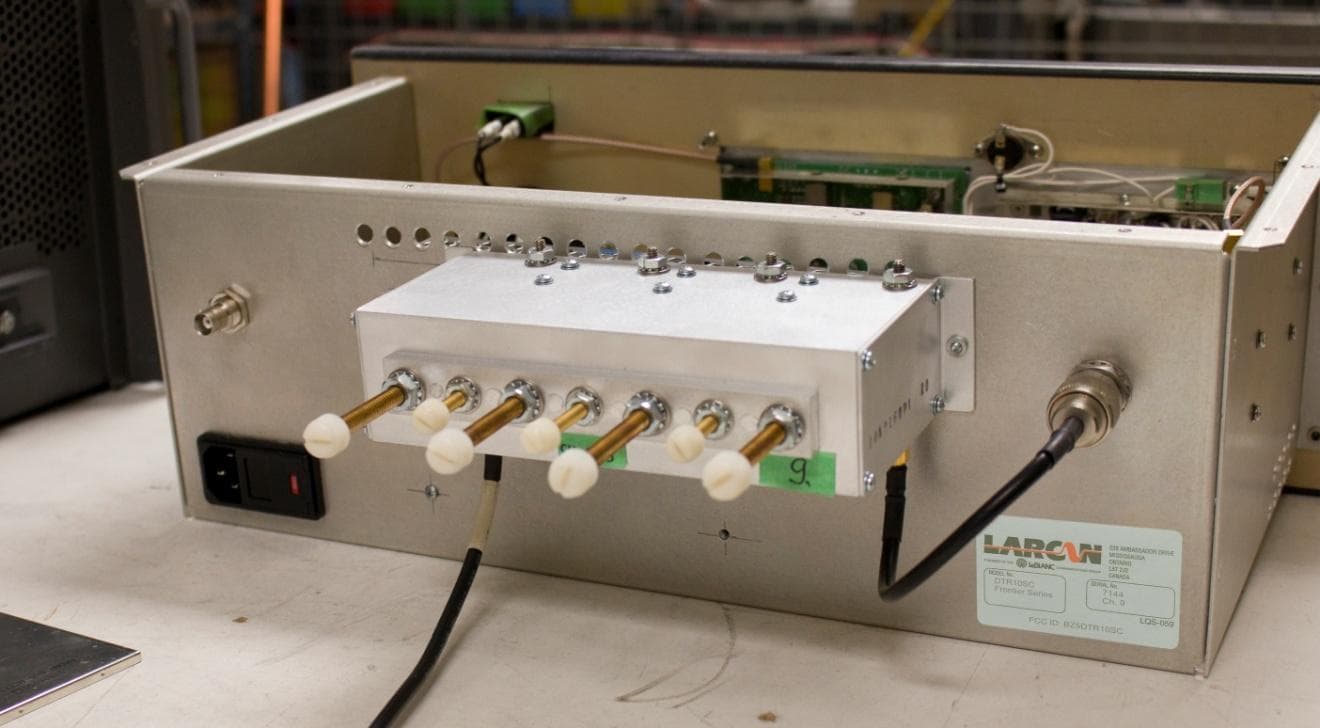
BZ5DTR10SC
Jun 16, 2014Digital Television Translator
Equipment Class
TBC - Licensed Broadcast Station Transmitter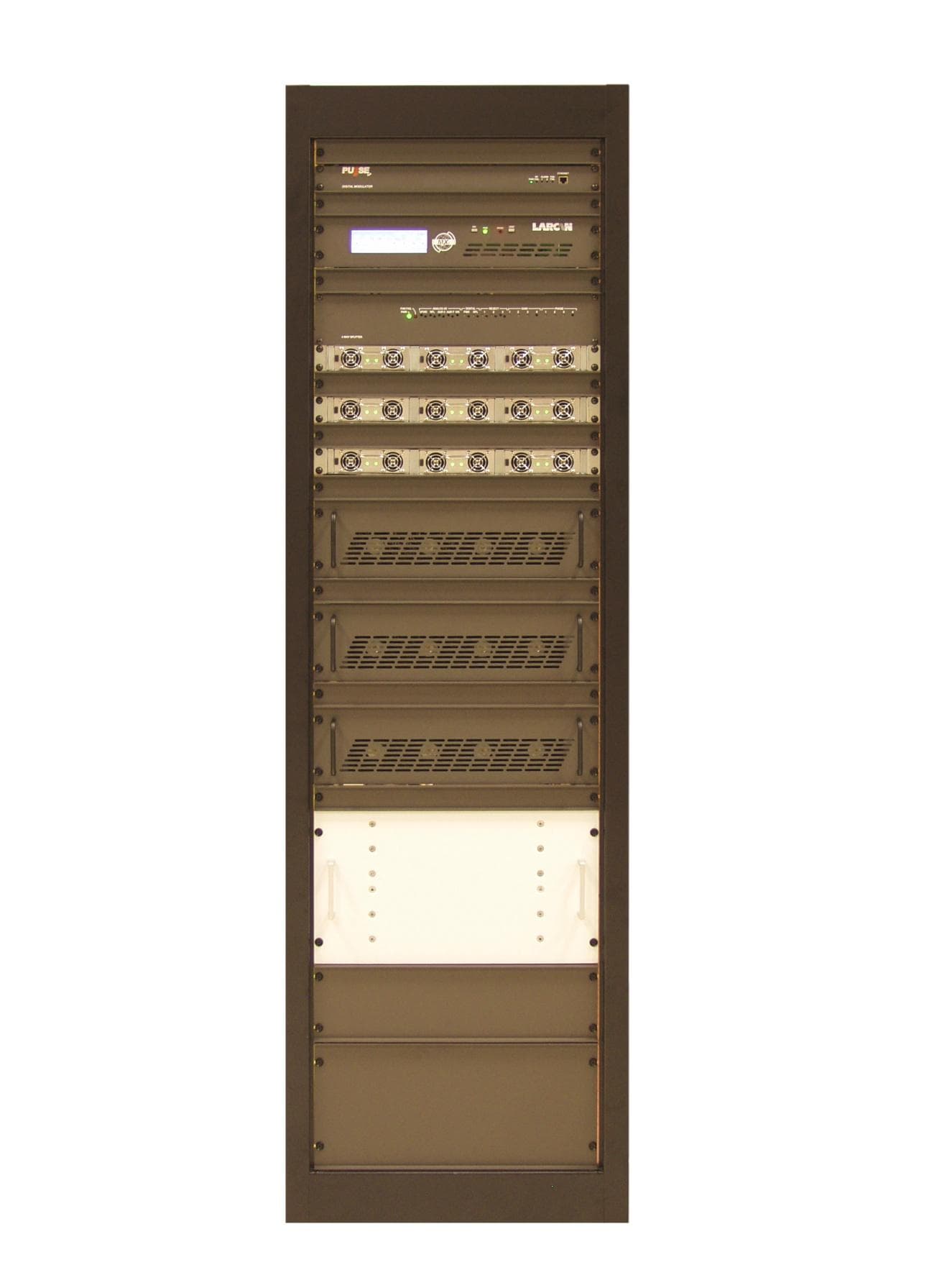
BZ5MXI1503U
Aug 04, 2013Television Broadcast Translator
Equipment Class
TBC - Licensed Broadcast Station Transmitter
BZ5MXI1002U
Jul 11, 2012Digital Television Translator
Equipment Class
TBC - Licensed Broadcast Station Transmitter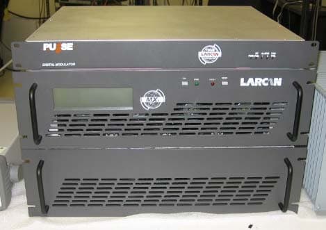
BZ5MXI501U
Nov 22, 2010Digital Television Broadcast Translator
Equipment Class
TBC - Licensed Broadcast Station TransmitterBZ5DTT250M
Jul 22, 2010Digital Television Broadcast Translator
Equipment Class
TBC - Licensed Broadcast Station Transmitter