CBF-ADVLJ45-450Body Worn Controller
Control Chief Corporation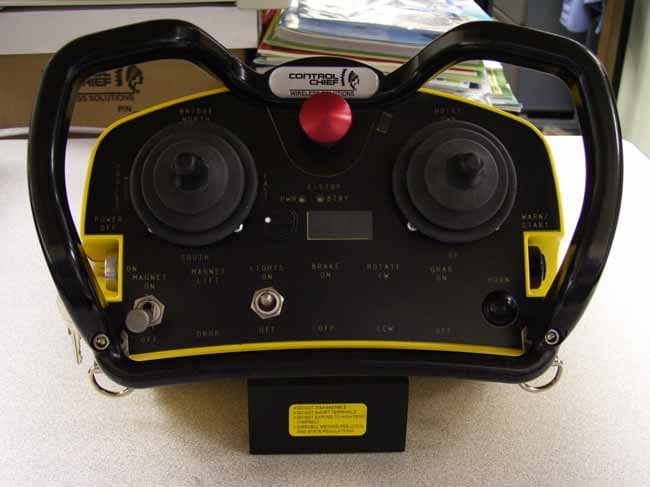
Click to zoom
Application Details
- Equipment Class
- TNB - Licensed Non-Broadcast Station Transmitter
- Date of Grant
- May 10, 2008
- Application Purpose
- Original Equipment
- Date of Application
- May 07, 2008
- Equipment Note
- Body Worn Controller
- Frequency Range
- 467.75000000 - 470.00000000
- Company
- Control Chief Corporation
- Country
- United States
Documents & Files
Document Text
Text extracted from the exhibit documents filed with the FCC. Open a document above to read the original.
Users Manual
Control Chief Corporation 200 Williams Street PO Box 141 Bradford, PA 16701 814-362-6811 * 1-800-233-3016 * 814-368-4133 (fax) www.controlchief.com Control Chief Corporation 200 Williams Street Bradford, PA 16701 814-362-6811 * 1-800- 233-3016 * 814-368-4133 (fax) www.controlchief.com Advantage Series LJ45 Transmitter Owner’s Manual Failure to return the Warranty Regi stration document (enclosed) to Control Chief within 30 days of purchase will void any warranty responsibilities on behalf of Control Chief Corporation ADVTG XMTR Control Chief Corporation, a world leader in wireless radio and infrared remote control products has developed and expanded upon this powerful technology. More than three decades of experience in designing, manufacturing and installing state-of-the-art remote communication systems emphasize Control Chief’s mission. Our systems are tailored to virtually any environment or application. Control Chief provides training, technical support, and comprehensive system design to maximize performance. It is our honor to uphold this reputation of innovative engineering and superior product performance. Publication: ADVTG XMTR Rev 01 Copyright © 2006 Contro l Chief Corporation All Rights Reserved. 200 Williams Street, Br adford, Pennsylvania, 16701 Web Page: www.controlchief.com Telephone: (814) 362-6811, FAX: (814) 368-4133 Installation Questions? Technical assistance is available from Control Chief. Please call us at 814-362-6811 or email the Service Department at [email protected] ADVANTAGE SERIES LJ45 TRANSMITTER OWNER’S MANUAL ADVTG XMTR Rev 01 14 Control Chief Corporation This page intentionally left blank. ADVANTAGE SERIES LJ45 TRANSMITTER OWNER’S MANUAL ADVTG XMTR Rev 01 i Control Chief Corporation TABLE OF CONTENTS CHAPTER 1 RADIO WARRANTY Warranty 1 Warranty Period 1 Warranty Service 1 Excluded Parts 1 Remarks 1 CHAPTER 2 SAFETY Safety Considerations 1 Warnings 3 CHAPTER 3 GENERAL INFORMATION Scope 4 System Description 4 Transmitter 4 CHAPTER 4 LJ 45 TRANSMITTER SPECIFICATIONS Table of Characteristics 5 CHAPTER 5 INSTALLATION Introduction 6 Battery Charger Placement 6 Securing the Transmitter 6 CHAPTER 6 TRANSMITTER OVERVIEW Introduction 7 Mechanical Features 7 Security Features 7 Motion and Auxiliary Switch Features 7 Other Features 7 ADVANTAGE SERIES LJ45 TRANSMITTER OWNER’S MANUAL ADVTG XMTR Rev 01 ii Control Chief Corporation CHAPTER 7 OPERATOR INSTRUCTION Introduction 8 Transmitter Operation 8 Recommended Practices 8 Emergency Shutdown 9 Spare Transmitter 9 Universal Transmitter 9 CHAPTER 8 TROUBLESHOOTING AND MAINTENANCE Introduction 10 Switch Maintenance 10 Radio Maintenance 10 General Troubleshooting 10 Radio Troubleshooting 10 CHAPTER 9 LITHIUM-ION BATTERY CARE & MAINTENANCE Battery Pack 11 Battery Care Summary 11 Charging Batteries 11 CHAPTER 10 PR ODUCT SUPPORT & SPARE PARTS Product Support 12 Returning Equipment for Repair 12 Contacting Control Chief 12 Spare Parts and Accessories 12 APPENDIX A TRANSMITTER SAFETY NOTE Function of the Switch Lever Guard 13 ADVANTAGE SERIES LJ45 TRANSMITTER OWNER’S MANUAL ADVTG XMTR Rev 01 13 Control Chief Corporation APPENDIX A TRANSMITTER SAFETY NOTE Function of the Switch Lever Guard The primary function of the transmitter switch guard (refer to photo below) is to prevent accidental activation of the motor levers. A secondary function is to facilitate operator ergonomics. The guard should not be used as a "handle" while performing a remote control operation with the transmitter. Consider the following scenario: the operator has completed a task and is walking away from the crane grasping the transmitter by the switch guard. If the unit is still ON and a hand accidentally moves one of the levers, the result could be an unintentional crane motion. To prevent this type of scenario, Control Chief provides a fitted harness with each transmitter for the operator to use during operations. The harness enables the operator to carry the unit around while performing their tasks, thereby prev enting an accidental switch lever actuation due to handling. Recommended Practices 1. Always wear a harness when performing remote control tasks with the transmitter. These components are designed to work together to provide the safest operational performance for the operator and the task he / she must perform. 2. When the operator has completed a shift or is about to take a break - the transmitter power switch must be turned off and the key removed. A transmitter should not be left unattended without being secured to prevent unauthorized operation. SWITCH LEVER GUARD ON/OFF KEYSWITC H ADVANTAGE SERIES LJ45 TRANSMITTER OWNER’S MANUAL ADVTG XMTR Rev 01 12 Control Chief Corporation 10 PRODUCT SUPPORT AND SPARE PARTS Product Support When contacting Control Chief Product Service please have the following information ready. ¾ Serial number: Located on the transmitter. ¾ Status of LED indicators on the crane mounted receiving unit. ¾ Description of the problem and its associated operational conditions/situation. Returning Equipment to Control Chief for Repair To return your transmitter to Control Chief for repair, please call Product Service to request a Return Material Authorization (RMA) number. The RMA number must be included on the shipping label and all correspondence related to the transmitter. Contacting Control Chief Control Chief P.O. Box 141, 200 Williams Street Bradford, PA 16701 PHONE: (814) 362-6811 FAX: (814) 368-4133 Toll Free: (800) 233-3016 Web Page:http://www.controlchief.com E-mail: [email protected] Spare Parts and Accessories If you require troubleshooting or help in part num ber identification, contact our Product Service group for assistance (as noted above). If you require additional battery packs, a replacement vest, or other components please contact our Customer Service department. Part Number Description 90-10-3-004 Battery, Li-Ion, Clip Style, 7.4VDC 90-10-2-011 Battery Charger, Li -Ion, Clip Style, 7.4VDC…
Text truncated - open the document above for the full version.
Cover Letter(s)
Response to ATCB Comments FCC ID: CBF-ADVLF45-450 1 Washington Laboratories, Ltd. 7560 LINDBERGH DRIVE GAITHERSBURG, MD 20879 (301) 417 – 0220 FAX # (301) 417 - 9069 February 22, 2008 Mr. Tim Johnson American Telecommunications Certification Body Inc. 6731 Whittier Ave McLean, VA 22101 RE: Comments of February 21, 2008 APPLICATION: CBF-ADVLF45-450 Control Chief Dear Mr. Johnson: Below are the comments that you have provided regarding the application for certification referenced above. Our responses to those comments are in bold italic. Many responses refer you to additional exhibit(s) which has been uploaded to the application folder at the ATCB website. Thank you for your attention. Please feel free to contact us for any additional information that you may require. Regards, Steven D. Koster EMC Operations Manager Brian J. Dettling Documentation Specialist WLL Project: 9805-9806 1) Due to various concerns recently seen about proper authority being given to others for FCC and/or IC matters, the agency letter (and confidentiality letters as well) should be signed by someone traceable to have the proper authority. For instance, the FCC site shows Rob Reese as the correct contact of authority for FCC matters. Therefore the agency letters should be signed by this contact or alternatively a letter showing who he has “deputized” (i.e. John Bryner) to sign on his behalf may be provided as well. R. Please see “Revised Letter of Agency” and “Revised Request for Confidentiality”. 2) Representative Internal View (photograph 1 in internal photos) appears to show a different RF module installed. Please review. R. An outdated photo was inadvertently used. Please see “LJ45-450 Internal Photos revised”. Response to ATCB Comments FCC ID: CBF-ADVLF45-450 2 3) The label appears to be in the battery compartment. Therefore kindly explain compliance with the following: FCC labels in user accessible areas As an option to placing the FCC label on the exterior of the device, the FCC label can be placed in a user accessible area if the following conditions are met. 1) The device is handheld. 2) The FCC identifier is visible at the time of purchase. Marketing the device without the battery installed when the label is in the battery compartment is acceptable. The FCC identifier on the box or additional documentation directing the user as to where to find the FCC label also satisfies this requirement. 3) The user accessible area must not require any special tools for access and the FCC label must not be placed on a removable part. R. The applicant attests: 1. Device is handheld. 2. Battery cover is not installed during shipping. Additional notation of FCC ID is included on outer packaging. 3. Battery compartment is not removable. No special tools are required to remove the compartment cover. 4) Kindly explain tunable bands of operation and actual tunable channel frequencies (i.e. report mentions only 7 channels). Please see attached. According to Part 2, I would appear that the grant would list the following bands (although this would be adjusted by actual tunable channels as well): 450 – 454 MHz 456 – 462.5375 MHz 462.7375 – 467.5375 MHz 467.7375 – 470 MHz Note that if exact tunable frequencies are not provided. When known, the FCC wants the above adjusted by this. Please provide actual tunable frequency list. Note that it appears that the original radio module (by doing research) may be capable of 256 channels. Please explain in detail. Also, if these differ from the tested 450, 460, and 470 MHz, kindly explain. R. Please see “ST500 data sheet”, “94-00-0-003_B”, and “freq search instructions”. Exhibits “94-00- 0-003_B” and “freq search instructions” should be considered part of the Operational Description and held confidential accordingly. The applicant describes the documents: The ST500 data sheet should give you all the information needed on the programming the Wood and Douglas radio modules. The frequency search instructions are an internal document detailing our procedure for selecting a frequency to be submitted for licensing at a given location. These instructions reference a frequency search utility from PerCon Corporation which has been customized for Control Chief to filter based on our band plan. The band plan is attached as 94-00-0-003_B.xls Once a frequency is selected and approved, that frequency is programmed by Control Chief into the Wood and Douglas module and cannot be readily changed by the user. 5) Parts List provided appears to match the first internal photograph and therefore do not applied since they appear to be for a different version. Please review. Response to ATCB Comments FCC ID: CBF-ADVLF45-450 3 R. An incorrect file was previously uploaded. Please see “LJ45-450 Assy Dwg 02”. 6) Internal views provided in the Tune Up Procedure appears to match the first internal photograph and therefore appears to be for a different version (i.e. test points not accessible and may be different). Please review. R. An incorrect file was previously uploaded. Please see “Advantage LJ Tuning Proc 02”. 7) Kindly provide RF Exposure information. Kindly confirm that the antenna element is > 20 cm from the user. Note the users manual mentions 20 cm from antenna to user (page 3). It is unsure if this distance applies. R. The antenna is closer to 8.5 cm from the person when used normally. The MPE report shows the safe distance to be 2.2cm, because the antenna is inside the unit, the user can not get that close to the antenna. 8) Users manual mentions 25 mW output power. 731 Form cites 45.7 mW. Please explain. R. 45.7mW is the measured power output, the manual has been changed to reflect this value. 9) Is NVLAP reference in test report still correct? R. Yes, testing was performed under that accreditation. 10) Reference to TIA/EIA 603 appears outdated. Please review. (i.e. B vs. C) R. The standard used was TIA/EIA 603 B 11) What is ANSI/TIA/EIA-603-93 (another reference to same standard?) R. Should be the TIA/EIA 60…
Text truncated - open the document above for the full version.
Cover Letter(s)
Response to ATCB Comments FCC ID: CBF-ADVLF45-450 1 Washington Laboratories, Ltd. 7560 LINDBERGH DRIVE GAITHERSBURG, MD 20879 (301) 417 – 0220 FAX # (301) 417 - 9069 April 28, 2008 Mr. Tim Johnson American Telecommunications Certification Body Inc. 6731 Whittier Ave McLean, VA 22101 RE: Comments of April 25, 2008 APPLICATION: CBF-ADVLF45-450 Control Chief Dear Mr. Johnson: Below are the comments that you have provided regarding the application for certification referenced above. Our responses to those comments are in bold italic. Many responses refer you to additional exhibit(s) which has been uploaded to the application folder at the ATCB website. Thank you for your attention. Please feel free to contact us for any additional information that you may require. Regards, Steven D. Koster EMC Operations Manager Brian J. Dettling Documentation Specialist WLL Project: 9805-9806 1) Comment 8 referenced an updated manual which does not appear to be received. Please review. R. “LJ45-450 User Manual revised” has now been uploaded. See page 5. 2) Table of frequency information contains frequencies information that is confusing. It appears the frequencies may be for multiple model devices. Which are applicable? Is it only model 450X? If so, then it appears this device would be listed as 452.3250 – 452.9875, 456.1875 – 462.5124, and 467.2125 – 467.9375 MHz. Please confirm/ explain. R. Please see “94-00-0-003_C”. Note the column “LJ”. The cells in that column are grey if the associated frequency is unavailable for the LJ-45 device, and are white if the associated frequency can be used. Response to ATCB Comments FCC ID: CBF-ADVLF45-450 2 3) Please explain use of EIA/TIA 603B. This standard is outdated and replaced with EIA/TIA 603 C. Please see: Land Mobile FM or PM Communications Equipment Measurement and Performance Standards (ANSI/TIA-603-B-2002)(Superseded by TIA-603-C-2004) http://www.tiaonline.org/standards/catalog/ Then enter “603” and press search Note: Page 3 of the test report also references ANSI/TIA/EIA-603-93. R. Please see “LJ45-450 Test Report rev 1”. TIA 603B was used because that is what is listed at the FCC website as a measurement procedure. TIA 603C is not there. It does caution that the list is not all inclusive, but I assumed that the latest procedure would be listed. I have a copy of the TIA 603C, but could not find any reference to this test procedure for FCC testing. Please advice as to where the procedure is called out for future reference. 4) Regarding RF exposure, FCC would require SAR testing for when power is > 60/freq(GHz). This equates to around 120 mW. FCC considers worse case radiated or conducted. Unfortunately information regarding the gain of the antenna or the EIRP of this device is not provided. Please provide. R. Please see “ANT-458-SP_Data_Sheet”. As you can see from the antenna data sheet, the manufacturer has estimated the antenna gain at -4dBi. This will put the EIRP well below the SAR testing requirements.
Internal Photos
No components other than antenna Module Top Shield removed Small Shield removed
RF Exposure Info
FCC ID:CBF-ADVLJ45-450 No SAR Evaluation Required if power is below the following threshold: Tunable Range F(GHz) Low F(GHz) High Center of Tunable Band (GHz) 60/f SAR Limitation mW based on center of band 0.450.470.46130.43 Maximum measured transmitter power: Pout Conducted (mW) Maximum Antenna Gain dBi Pout EIRP (mW) 45.7-418.19 Threshold for no SAR evaluation is 130.43 mW Maximum TX Power is 45.7 mW Conducted and 18.19 mW EIRP Conclusion: No SAR evaluation required since maximum Transmitter Pout (both conducted and EIRP) is below FCC threshold
Test Report
FCC & Industry Canada Certification Test Report For the Control Chief Corporation A DVANTAGE LJ45 TRANSCEIVER FCC ID: CBF-ADVLJ45-450 IC ID: 1339A-LJ450001 WLL JOB# 9805 November 30, 2007 Revision 1 issued March 14, 2008 Prepared for: Control Chief Corporation 200 Williams Street Bradford, PA 16701 Prepared By: Washington Laboratories, Ltd. 7560 Lindbergh Drive Gaithersburg, Maryland 20879 Control Chief Corp Advantage LJ45 Transceiver FCC Certification Test Report November 2007 FCC & Industry Canada Certification Test Report for the Control Chief Corporation Train Chief II Lightweight OCU FCC ID: CBF-ADVLJ45-450 IC ID: 1339A-LJ450001 November 30, 2007 Revision 1 issued March 14, 2008 WLL JOB# 9805 Prepared by: John P. Repella Q A Manager Reviewed by: Steven D. Koster EMC Operations Manager Control Chief Corporation Advantage LJ45 Transceiver FCC Certification Test Report November 2007 WLL Report #9805-01 Rev 1 - ii - © 2008 Washington Laboratories, Ltd. Abstract This report has been prepared on behalf of Control Chief Corporation to support the attached Application for Equipment Authorization. The test report and application are submitted for a Licensed Transmitter under Part 90 of the FCC Rules and Regulations and Spectrum Management and Telecommunications Policy RSS-119 of Industry Canada. This Certification Test Report documents the test configuration and test results for a Control Chief Corporation Advantage LJ45 Transceiver. Testing was performed on an Open Area Test Site (OATS) of Washington Laboratories, Ltd, 7560 Lindbergh Drive, Gaithersburg, MD 20879. Site description and site attenuation data have been placed on file with the FCC's Sampling and Measurements Branch at the FCC laboratory in Columbia, MD. The Industry Canada OATS numbers are 3035A-1 and 3035A-2 for Washington Laboratories, Ltd. Site 1 and Site 2, respectively. Washington Laboratories, Ltd. has been accepted by the FCC and approved by NIST NVLAP (NVLAP Lab Code: 200066-0) as an independent FCC test laboratory. The Control Chief Corporation Advantage LJ45 Transceiver complies with the limits for a Licensed Transmitter device under FCC Part 90 and Industry Canada RSS-119. Revision 1 was issued on March 14, 2008 to address a typographical error that inadvertently created concern for a reported test result. Control Chief Corporation Advantage LJ45 Transceiver FCC Certification Test Report November 2007 WLL Report #9805-01 Rev 1 - iii - © 2008 Washington Laboratories, Ltd. Table of Contents Abstract ........................................................................................................................................... ii 1 Introduction ..........................................................................................................................1 1.1 Compliance Statement .....................................................................................................1 1.2 Test Scope ........................................................................................................................1 1.3 Contract Information ........................................................................................................1 1.4 Test Dates ........................................................................................................................1 1.5 Test and Support Personnel .............................................................................................1 2 Equipment Under Test .........................................................................................................2 2.1 EUT Identification & Description ...................................................................................2 2.2 Test Configuration ...........................................................................................................2 2.3 Testing Algorithm ............................................................................................................2 2.4 Test Location ...................................................................................................................3 2.5 Measurements ..................................................................................................................3 2.5.1 References ....................................................................................................................3 2.6 Measurement Uncertainty ................................................................................................3 3 Test Equipment ....................................................................................................................4 4 Test Results ..........................................................................................................................5 4.1 RF Power Output: (FCC Part §2.1046 and Industry Canada RSS-119) ..........................5 4.2 Occupied Bandwidth: (FCC Part §2.1049 and Industry Canada RSS-119, 6.7) .............6 4.3 Conducted Spurious Emissions at Antenna Terminals (FCC Part §2.1051 and Industry Canada RSS-119) .......................................................................................................................10 4.4 Radiated Spurious Emissions: (FCC Part §2.1053 and Industry Canada RSS-119) .....18 4.4.1 Test Procedure .........................................................................................................18 4.5 Receiver Spurious Emissions .........................................................................................20 4.5.1 Test Procedure .........................................................................................................20 4.6 Frequency Stability: (FCC Part §2.1055 and Industry Canada RSS-119, Section 7) ....25 4.7 Transient Frequency Behavior (FCC §90.214 and RSS-119 Section 6.5) ....................26 4.7.1 Procedure ...................................................................................................................26 List of Tables Table 1. Devic…
Text truncated - open the document above for the full version.
Contact Information
Applicant
Jake Bryner(VP Product Design & Development)
Technical Contact
Washington Laboratories, Ltd.Steven D. Koster
[email protected]301-216 1500
7560 Lindbergh Drive · Gaithersburg, Maryland · United States
Non-Technical Contact
Washington Laboratories, Ltd.Brian J. Dettling
[email protected]301-216 1500
Test Firm
Washington Laboratories, Ltd.John Repella
Technical Specifications
| # | Rule Parts | Frequency Range | Power Output | Emission | Tolerance |
|---|---|---|---|---|---|
| 4 | 9 | 467.75 MHz - 470 MHz | 11.00 mW | 9K65F1D | 2 ppm |
Other Applications from Control Chief Corporation
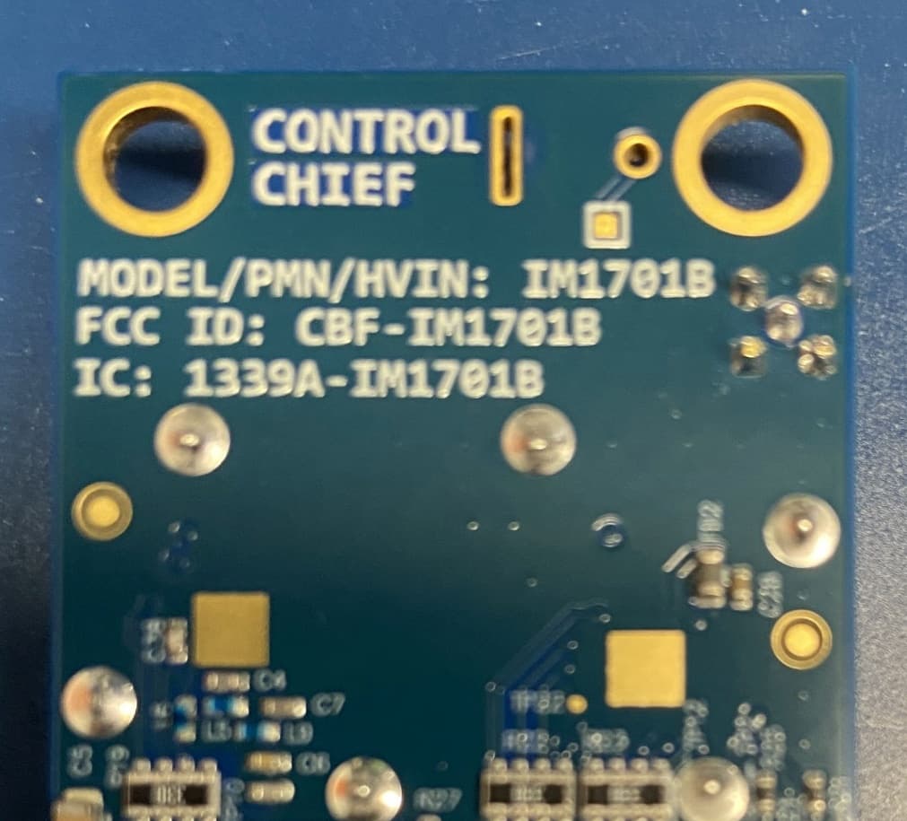
CBF-IM1701B
Jun 22, 2026Battery powered radio
Equipment Class
DSS - Part 15 Spread Spectrum Transmitter
CBF-800R
Feb 07, 2012Wireless Door Opening System, Receiver
Equipment Class
DXT - Part 15 Low Power Transceiver, Rx Verified
CBF-L999
Feb 07, 2012Wireless Door Opening System, Hand Held Controller
Equipment Class
DXT - Part 15 Low Power Transceiver, Rx Verified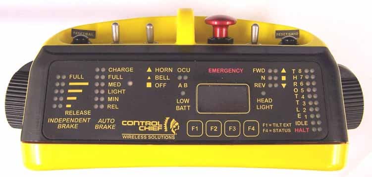
CBF-LTOCU-M
Feb 18, 2006LOCOMOTIVE REMOTE CONTROL SYSTEM
Equipment Class
TNT - Licensed Non-Broadcast Transmitter Worn on Body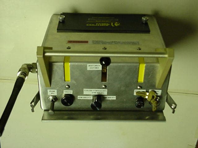
CBFMDR-173
Aug 24, 2002MDR-8410 / 84100 Transmitter
Equipment Class
TNB - Licensed Non-Broadcast Station Transmitter