CBF-LTOCU-MLOCOMOTIVE REMOTE CONTROL SYSTEM
Control Chief Corporation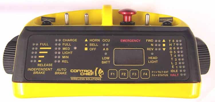
Click to zoom
Application Details
- Equipment Class
- TNT - Licensed Non-Broadcast Transmitter Worn on Body
- Date of Grant
- Feb 18, 2006
- Application Purpose
- Original Equipment
- Date of Application
- Feb 16, 2006
- Equipment Note
- LOCOMOTIVE REMOTE CONTROL SYSTEM
- Frequency Range
- 450.00000000 - 470.00000000
- Company
- Control Chief Corporation
- Country
- United States
Documents & Files
Document Text
Text extracted from the exhibit documents filed with the FCC. Open a document above to read the original.
Users Manual
95-00-0-062, Rev 09 c-1 Control Chief Corporation PO Box 141 Bradford, PA 16701 (814) 362-6811 TRAIN CHIEF® II LOCOMOTIVE REMOTE CONTROL SYSTEM w/LIGHTWEIGHT OCU-BT OPERATOR'S MANUAL Document Number: 95-00-0-062 Revision: 08 Date: 8/26/05 Issued By: CWY Checked By: Approved By: TRAIN CHIEF® II LRCS W/ Lightweight OCU-BT – OPERATORS MANUAL 95-00-0-062, Rev 09 c-2 Control Chief Corporation Revision History Revision Release Date Comments 01 Mar 2005 Original 06 May 2005 Sec 6: added fig 6-1a1,6-1b, 6-1c. Added figs 8-1, 8-2, 8-3 and callouts. Sec 8 replacement parts aligned to figures and Eng’g dwgs SKT00123 & 00124. 06.1 May 11 2005 Modified figures 6-5, 8-3. Added watermark. 07 5/13/05 Revised jpg images w/mushroom E-stop, added LED images Sect 7. Subst OCU-BT to all that applies. 7.1 6/10/05 Replaced jpg images in Sect 7.2 & 7.3 08 6/17/05 Pg 1-1, LRC to LRCS+definition 09 8/26/05 Added warning on page 1-6. (rlr) 09a 12/27/05 Specification edits. (rlr) Publication: 95-00-0-062 Copyright © 2004, 2005 Control Chief Corporation All Rights Reserved. 200 Williams Street, Bradford, Pennsylvania, 16701 Web Page: www.controlchief.com Telephone: (814) 362-6811, FAX: (814) 368-4133 TRAIN CHIEF® II is a trademark of Control Chief Corporation. Communicator® is a registered trademark of Control Chief Corporation. SLC 500 is a trademark of Rockwell Automation. PanelView is a trademark of Rockwell Automation. TRAIN CHIEF® II LRCS W/ Lightweight OCU-BT – OPERATORS MANUAL 95-00-0-062, Rev 09 i Control Chief Corporation TABLE OF CONTENTS CHAPTER 1 INTRODUCTION / SAFETY Introduction 1-1 Common Acronyms 1-1 Receiver / Controller Unit 1-1 Installation Kit 1-2 Lightweight OCU-BT 1-2 Reference Drawings 1-2 Safety 1-3 CHAPTER 2 SPECIFICATIONS General Specifications 2-1 Lightweight OCU-BT Specifications 2-1 Receiver / Controller Unit Specifications 2-1 CHAPTER 3 PHYSICAL DESCRIPTION AND INSTALLATION The Lightweight OCU-BT 3-1 The Receiver / Controller Unit 3-6 The Installation Kit 3-11 Receiver / Controller Unit Mounting 3-12 Locomotive Interface 3-13 General Installation Practices 3-15 CHAPTER 4 START UP AND OPERATING PROCEDURES Locomotive Stops (Definitions) 4-1 Setup and Remote Control Operations 4-2 Transfer to Remote Control and PCS Reset 4-8 Air Brakes and Safety Features Test 4-9 Normal Locomotive Operation 4-10 Selective Dual Control 4-15 Transferring from Remote to Manual 4-17 TRAIN CHIEF® II LRCS W/ Lightweight OCU-BT – OPERATORS MANUAL 95-00-0-062, Rev 08 1-1 Control Chief Corporation 1 INTRODUCTION / SAFETY 1.1 Introduction This Owner’s Manual provides operating and troubleshooting information for the installer and end user of the Train Chief® II Locomotive Remote Control System (LRCS) with a Lightweight Operator Control Unit (OCU) Brake & Throttle variant (BT). The Train Chief® II LRCS has been designed as a permanently installed (“fixed”) system, directly interfaced to the appropriate locomotive electrical and pneumatic controls. The system consists of the following main components: (1) - the receiver / controller unit, (2) - the wireless remote-control radio Operator Control Unit (OCU), (3) - the installation kit. 1.2 Common Acronyms CFR - Code of Federal Regulations RCL - Remote Control Locomotive FRA - Federal Railroad Administration RCO - Remote Control Operator LRCS - Locomotive Remote Control System RCU - Receiver Control Unit OCU - Operator Control Unit RCT - Remote Control Transmitter PTC - Positive Train Control RCR - Remote Control Receiver PLC - Programmable Logic Controller 1.3 Receiver / Controller Unit The receiver / controller unit (RCU) contains the main control electronics and pneumatic hardware of the remote control system. This includes; the PLC controller (the Allen Bradley SLC 500), the Control Chief Communicator® module and Control Chief Watchdog module, analog and discrete interface modules, pneumatic proportional control valves, air regulation, control relays, solenoid valves, and pressure sensing devices. The RCU interface to the locomotive involves both electrical and pneumatic connections. The electrical interface is primarily accomplished through DC relay contact closures, wiring into the existing locomotive’s electrical control system. The pneumatic interface typically involves direct air service tie-ins using the dedicated pneumatic control devices in the RCU. A dedicated DC/DC converter and line conditioning module are provided to interface the locomotive’s existing DC supply to the RCU. Figure 1-1 – The Receiver / Controller Unit TRAIN CHIEF® II LRCS W/ Lightweight OCU-BT – OPERATORS MANUAL 95-00-0-062, Rev 08 1-2 Control Chief Corporation 1.4 The Installation Kit In order to effectively and reliably interface to the locomotive controls / operations, various kitted items are provided to complete the installation. An antenna kit is provided to allow the radio antenna to be mounted on the locomotive cab. Surge suppressors are provided for installation on all inductive devices (i.e. solenoid coils, electrical contactor coils, etc.) to minimize Electro Magnetic Interference (EMI). Optional colored status lights can also be provided to provide visual indications during remote operations. 1.5 The Lightweight OCU The lightweight OCU is rugged and durable, with a custom designed encapsulated antenna for maximum performance. Reliable radio communication distances up to 5200 feet can be achieved (depending on operating environment). The comfortable ergonomic shape eliminates sharp corners and puts a wide range of functions within easy reach. The top display panel instantly shows the operator the current control settings without having to remember the switch movements. Figure 1-2: Typical Lightweight OCUs Speed Control Variant Brake-Throttle Variant 1.6 Reference Drawings The system drawing package contains the following typical drawings, which are referenced throughout this document. These drawings will be specific to your system with exact configuration details. Note: “XXXX” …
Text truncated - open the document above for the full version.
Cover Letter(s)
American Telecommunications Certification Body Inc. 6731 Whittier Ave, McLean, VA 22101 February 2, 2006 RE: FCC ID: CBF-LTOCU-M_ATCB003152 Attention: Greg Snyder / Brian Dettling I have a few comments on this Application. Please note that further comments may arise in response to answers provided to the questions below. 1. Please note that the company number (1339) does not exist in the IC data base. Please provide a corrected IC application form and label using a valid IC company number. 2. Please note that while the device appears to be of a low enough power not to require SAR testing when used in an occupational/controlled rf environment, rf exposure must still be addressed. Please note that it must still be justified for use in a controlled environment in order to meet this exception. Please provide an rf exhibit that show occupational use. 3. Please provide a manual that sows this device is limited to the occupational/controlled use environment. Dennis Ward mailto:[email protected] The items indicated above must be submitted before processing can continue on the above referenced application. Failure to provide the requested information may result in application termination. Correspondence should be considered part of the permanent submission and may be viewed from the Internet after a Grant of Equipment Authorization is issued. Please do not respond to this correspondence using the email reply button. In order for your response to be processed expeditiously, you must submit your documents through the AmericanTCB.com website. Also, please note that partial responses increase processing time and should not be submitted. Any questions about the content of this correspondence should be directed to the sender.
Cover Letter(s)
Response to ATCB Comments FCC ID: CBF-LTOCU-M 1 Washington Laboratories, Ltd. 7560 LINDBERGH DRIVE GAITHERSBURG, MD 20879 (301) 417 – 0220 FAX # (301) 417 - 9069 February 16, 2006 Mr. Dennis Ward American Telecommunications Certification Body Inc. 6731 Whittier Ave McLean, VA 22101 RE: Comments of February 2, 2006 APPLICATION: CBF-LTOCU-M Control Chief Corporation Dear Mr. Ward: Below are the comments that you have provided regarding the application for certification referenced above. Our responses to those comments are in bold italic. Many responses refer you to additional exhibit(s) which has been uploaded to the application folder at the ATCB website. Thank you for your attention. Please feel free to contact us for any additional information that you may require. Regards, Gregory M. Snyder Chief EMC Engineer, Wireless/Telco Services Manager Brian J. Dettling Documentation Specialist WLL Project: 8896-9023 1) Please note that the company number (1339) does not exist in the IC data base. Please provide a corrected IC application form and label using a valid IC company number. R. Thank you for your assistance in this: Industry Canada has directed Control Chief to add an “A” suffix to the number “1339”. Revised Form RSP100 and label documents have been supplied. 2) Please note that while the device appears to be of a low enough power not to require SAR testing when used in an occupational/controlled rf environment, rf exposure must still be addressed. Please note that it must still be justified for use in a controlled environment in order to meet this exception. Please provide an rf exhibit that show occupational use. R. Please see the exhibit “OCU RF Exposure Information” that addresses this comment. Response to ATCB Comments FCC ID: CBF-LTOCU-M 2 3) Please provide a manual that shows this device is limited to the occupational/controlled use environment. R. A statement addressing the occupational controlled environment has been added to the revised manual on page 2-2.
Cover Letter(s)
Per discussion with the FCC, the grant has been revised to incorporate the following grant notes: "Power output listed is at the antenna connector. Only the 1/4 wave stubby antenna tested with the device as shown in the filing may be used with this transmitter. Use of any other antenna(s) requires a class 2 permissive change. The antenna(s) must be installed to provide a minimum separation distance of at least 2.5 cm from all persons. Users and installers must be provided with antenna installation instructions and transmitter operating conditions for satisfying RF exposure compliance."
RF Exposure Info
Control Chief Corporation Train Chief II Lightweight OCU WLL Job: 8896 February 2006 RF Exposure Exhibit for the Control Chief Corporation Train Chief II Lightweight OCU FCC ID: CBF-LTOCU-M IC: 1339A-R222991 The Control Chief OCU is considered for general population RF exposure levels. A ¼ wave whip antenna is located inside the enclosure of the unit and provides greater than 9cm of separation from the user during operation. With the use of tilt sensors, only one orientation of the device is possible thus maintaining the separation distance. The maximum output power of the unit at a 100% continuous operation is 422mW operating from 450 – 470MHz. The average power, however, based on the duty cycle of operation is significantly less than this maximum output power. The OCU system requires a heart beat for all control functions, meaning that all control functions must be refreshed at least once every 1.25 seconds or the controller will initiate a safe stop mode. At every 1.25 seconds the unit sends a continuous packet rate of 250mSec and packet duration of 112mSec. Using the formula below yields an average power output of <200mW. Pavg = Ppk*(packet duration/packet rate) = 422mW*(112mSec/250mSec) = 190mW Per the TCB Exclusion list published on 17 July 2002 the following calculation is used for determining the applicability of TCB approval and routine SAR evaluation: Exposure category low threshold high threshold general population (60/fGHz) mW, d< 2.5 cm (120/fGHz) mW, d ≥2.5 cm (900/fGHz) mW, d< 20 cm occupational (375/fGHz) mW, d< 2.5 cm (900/fGHz) mW, d ≥2.5 cm (2250/fGHz) mW, d< 20 cm Control Chief Corporation Train Chief II Lightweight OCU WLL Job: 8896 February 2006 The OCU is being evaluated to the general population exposure category and is >2.5cm from the body when in use. Therefore the following calculation is made for determining the low threshold power: 120/0.46 = 260mW The OCU average power is 190mW which is below the low threshold and therefore routine SAR evaluation is not required and the unit qualifies for TCB approval.
Test Report
FCC & Industry Canada Certification Test Report For the Control Chief Corporation Train Chief II Lightweight OCU CBF-LTOCU-M 1339-R222991 WLL JOB# 8896-9023 January 30, 2006 Prepared for: Control Chief Corporation 200 Williams Street Bradford, PA 16701 Prepared By: Washington Laboratories, Ltd. 7560 Lindbergh Drive Gaithersburg, Maryland 20879 %%CUSTNAME%% %%CUSTEUTNAME%% FCC Certification Test Report %%REPORTDATE%% FCC & Industry Canada Certification Test Report for the Control Chief Corporation Train Chief II Lightweight OCU FCC ID: CBF-LTOCU-M IC ID: 1339-R222991 January 30, 2006 WLL JOB# 8896-9023 Prepared by: Brian J. Dettling Documentation Specialist Reviewed by: Gregory M. Snyder Chief EMC Engineer Control Chief Corporation Train Chief II Lightweight OCU FCC Certification Test Report January 2006 WLL Report #8896-9023-01 - ii - © 2006 Washington Laboratories, Ltd. Abstract This report has been prepared on behalf of Control Chief Corporation to support the attached Application for Equipment Authorization. The test report and application are submitted for a Licensed Transmitter under Part 90 of the FCC Rules and Regulations and Spectrum Management and Telecommunications Policy RSS-119 of Industry Canada. This Certification Test Report documents the test configuration and test results for a Control Chief Corporation Train Chief II Lightweight OCU. Testing was performed on an Open Area Test Site (OATS) of Washington Laboratories, Ltd, 7560 Lindbergh Drive, Gaithersburg, MD 20879. Site description and site attenuation data have been placed on file with the FCC's Sampling and Measurements Branch at the FCC laboratory in Columbia, MD. The Industry Canada OATS numbers are 3035A-1 and 3035A-2 for Washington Laboratories, Ltd. Site 1 and Site 2, respectively. Washington Laboratories, Ltd. has been accepted by the FCC and approved by NIST NVLAP (NVLAP Lab Code: 200066-0) as an independent FCC test laboratory. The Control Chief Corporation Train Chief II Lightweight OCU complies with the limits for a Licensed Transmitter device under FCC Part 90 and Industry Canada RSS-119. Control Chief Corporation Train Chief II Lightweight OCU FCC Certification Test Report January 2006 WLL Report #8896-9023-01 - iii - © 2006 Washington Laboratories, Ltd. Table of Contents Abstract ........................................................................................................................................... ii 1 Introduction..........................................................................................................................1 1.1 Compliance Statement .....................................................................................................1 1.2 Test Scope ........................................................................................................................1 1.3 Contract Information........................................................................................................1 1.4 Test Dates ........................................................................................................................1 1.5 Test and Support Personnel .............................................................................................1 2 Equipment Under Test .........................................................................................................2 2.1 EUT Identification & Description ...................................................................................2 2.2 Test Configuration ...........................................................................................................2 2.3 Testing Algorithm............................................................................................................2 2.4 Test Location ...................................................................................................................2 2.5 Measurements ..................................................................................................................3 2.5.1 References................................................................................................................3 2.6 Measurement Uncertainty................................................................................................3 3 Test Equipment ....................................................................................................................4 4 Test Results ..........................................................................................................................5 4.1 RF Power Output: (FCC Part §2.1046 and Industry Canada RSS-119) ..........................5 4.2 Occupied Bandwidth: (FCC Part §2.1049 and Industry Canada RSS-119, 6.7) .............6 4.3 Conducted Spurious Emissions at Antenna Terminals (FCC Part §2.1051 and Industry Canada RSS-119).........................................................................................................................8 4.4 Radiated Spurious Emissions: (FCC Part §2.1053 and Industry Canada RSS-119) .....16 4.4.1 Test Procedure.....................................................................................................16 4.5 Receiver Spurious Emissions.........................................................................................18 4.5.1 Test Procedure.....................................................................................................18 4.6 Frequency Stability: (FCC Part §2.1055 and Industry Canada RSS-119, Section 7)....20 4.7 Transient Frequency Behavior (FCC §90.214 and RSS-119 Section 6.5) ....................21 4.7.1 Procedure ...............................................................................................................21 List of Tables Table 1. Device Summary............................................................................................................... 2 Table 2: Test Equipment List....................................................................................…
Text truncated - open the document above for the full version.
Contact Information
Applicant
Jake Bryner(VP Product Design & Development)
Technical Specifications
| # | Rule Parts | Frequency Range | Power Output | Emission | Tolerance |
|---|---|---|---|---|---|
| 1 | 90 | 450 MHz - 470 MHz | 422.00 mW | 9K65F1D | 2.5000000000 ppm |
Other Applications from Control Chief Corporation
CBF-IM1701B
Jun 22, 2026Battery powered radio
Equipment Class
DSS - Part 15 Spread Spectrum Transmitter
CBF-800R
Feb 07, 2012Wireless Door Opening System, Receiver
Equipment Class
DXT - Part 15 Low Power Transceiver, Rx Verified
CBF-L999
Feb 07, 2012Wireless Door Opening System, Hand Held Controller
Equipment Class
DXT - Part 15 Low Power Transceiver, Rx Verified
CBF-ADVLJ45-450
May 10, 2008Body Worn Controller
Equipment Class
TNB - Licensed Non-Broadcast Station Transmitter
CBFMDR-173
Aug 24, 2002MDR-8410 / 84100 Transmitter
Equipment Class
TNB - Licensed Non-Broadcast Station Transmitter