CBF-IM1701BBattery powered radio
Control Chief Corporation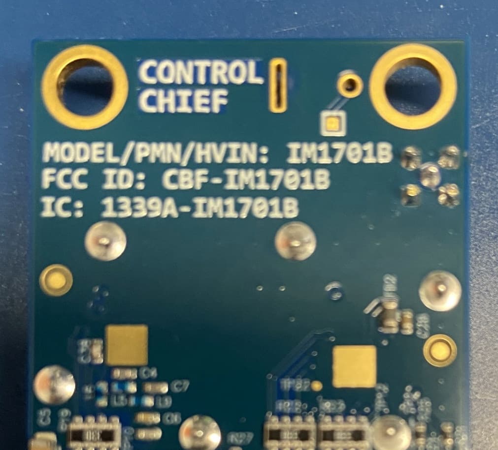
Click to zoom
Application Details
- Equipment Class
- DSS - Part 15 Spread Spectrum Transmitter
- Date of Grant
- Jun 22, 2026
- Application Purpose
- Original Equipment
- Equipment Note
- Battery powered radio
- Frequency Range
- 902.30000000 - 927.80000000
- Company
- Control Chief Corporation
- Country
- United States
Documents & Files
Document Text
Text extracted from the exhibit documents filed with the FCC. Open a document above to read the original.
Users Manual
vImpulse User Manual Version 1.7 May 29, 2026 99 Garnsey Road, Suite 200 Suite 200 Pittsford, New York 14534 Voice: (585) 419-9555 FAX: (585) 248-0537 http://www.vanteon.com 5/29/2026 Vanteon Proprietary Page 1 of 18 Table of Contents 1. Document Overview .................................................................................................................................................... 3 1.1 Scope ...................................................................................................................................................................... 3 1.2 Intended Audience .................................................................................................................................................. 3 1.3 Definitions, Acronyms, and Abbreviations ............................................................................................................. 3 1.4 Conventions ............................................................................................................................................................ 3 2. Agency Notices ............................................................................................................................................................ 4 2.1 Federal Communications Commission (FCC) ...................................................................................................... 4 2.2 Industry Canada (IC) .............................................................................................................................................. 4 2.3 Module Integration Instructions .............................................................................................................................. 5 3. Hardware Installation ................................................................................................................................................... 7 3.1 Antenna ................................................................................................................................................................... 7 3.2 Power Supply .......................................................................................................................................................... 8 3.3 Connectors .............................................................................................................................................................. 8 4. Host Console Interface ................................................................................................................................................ 9 4.1 UART ....................................................................................................................................................................... 9 4.2 Command Summary .............................................................................................................................................. 9 4.3 Configuration ........................................................................................................................................................... 9 4.4 Help ....................................................................................................................................................................... 11 4.5 Hopping ................................................................................................................................................................. 11 4.6 Receiving Packets ................................................................................................................................................ 11 4.7 Sending Packets ................................................................................................................................................... 12 4.8 Status ..................................................................................................................................................................... 14 4.9 System ................................................................................................................................................................... 15 4.10 Version .................................................................................................................................................................. 16 4.11 Comment ............................................................................................................................................................... 16 5. vImpulse LEDs ........................................................................................................................................................... 17 5.1 LED Usage ............................................................................................................................................................ 17 6. Board Dimensions ...................................................................................................................................................... 18 6.1 Outline and Hole Locations .................................................................................................................................. 18 5/29/2026 Vanteon Proprietary Page 2 of 18 Approvals Massimo Amadio, Project Manager Date Revision History Revision Date Author Description 1.0 9/13/2016 Gerry Callahan Release 1.1 9/28/2016 Gerry Callahan Release 1.1 1.1a 10/19/16 Joseph Ott Release 1.1a 1.2 11/11/2016 Gerry Callahan Additions, corrections 1.3 11/15/2016 Joseph Ott Additions, updates 1.3a 3/14/2017 Gerry Callahan Updates for FCC test 1.3b 6/1/2017 Gerry Callahan Agency notices 1.3c 6/12/2017 Gerry Callahan Added sync query 1.4 6/13/2017 Gerry Callahan Add SyncWord command. Filled in some missing commands. 1.4a 9/19/2017 Gerry Callahan Reformatted Antenna commands 1.4b 10/13/2017 Gerry Callahan Added antenna list, and notification for Canada. 1.4c 12/12/2017 Gerry Callahan Adde…
Text truncated - open the document above for the full version.
Users Manual
Regulatory Module Integration Instructions FCCID: CBF-IM1701B IC: 1339A-IM1701B This Module has been granted modular approval for Mobile applications. OEM integrators for Host products may use the Module in their final products without additional FCC / IC certification if they meet the following conditions. Otherwise, additional FCC / IC approvals must be obtained. • The user’s manual for the Host product must clearly indicate the operating requirements and conditions that must be observed to ensure compliance with current FCC / IC RF exposure guidelines. • To comply with FCC / IC regulations limiting both maximum RF output power and human exposure to RF radiation, the maximum antenna gain including cable loss in a Mobile-only exposure condition must not exceed 5.4dBi. The following are certified antennas: o TE Linx ANT-916-MHW-RPS-S. The antenna must be customized to replace the SMA connector with a MMCX male plug. The antenna must maintain a minimum separation of 20 centimeters from the user and nearby persons during use. • The external surfaces of the Host product must clearly display the following statements: This device contains FCCID: CBF-IM1701B This equipment contains equipment certified under IC: 1339A-IM1701B The final Host / Module combination may also need to be evaluated against the FCC Part 15B criteria for unintentional radiators in order to be properly authorized for operation as a Part 15 digital device. The Module is not intended for use as a Portable device, therefore, if the final Host / Module combination is intended for use as a Portable device, the Host manufacturer is responsible for separate approvals for the specific absorption rate SAR requirements from FCC Part 2.1093 and RSS-102. The Module is intended for use as a Mobile device, formally defined below. FCC Definition of Mobile Mobile: (§2.1091) (b) — A Mobile device is defined as a transmitting device designed to be used in other than fixed locations and to generally be used in such a way that a separation distance of at least 20 centimeters is normally maintained between the transmitter’s radiating structure(s) and the body of the user or nearby persons. Per §2.1091d(d)(4) In some cases (for example, modular or desktop transmitters), the potential conditions of use of a device may not allow easy classification of that device as either Mobile or Portable. In these cases, applicants are responsible for determining minimum distances for compliance for the intended use and installation of the device based on evaluation of either specific absorption rate (SAR), field strength, or power density, whichever is most appropriate. Regulatory Module Integration Instructions FCCID: CBF-IM1701B IC: 1339A-IM1701B Simultaneous Transmission Evaluation This Module has not been evaluated or approved for simultaneous transmission as it is impossible to determine the exact multi-transmission scenario that a Host manufacturer may choose. Any simultaneous transmission condition established through Module integration into a Host product must be evaluated per the requirements in KDB447498D01(8). These requirements include, but are not limited to: • Transmitters and Modules certified for Mobile or Portable exposure conditions can be incorporated in Mobile Host devices without further testing or certification when: o The closest separation among all simultaneous transmitting antennas is >20 cm, Or o Antenna separation distance and MPE compliance requirements for ALL simultaneous transmitting antennas have been specified in the application filing of at least one of the certified transmitters within the Host device. In addition, when transmitters certified for Portable use are incorporated in a Mobile Host device, the antenna(s) must be >5 cm from all other simultaneous transmitting antennas. o All antennas in the final product must be at least 20 cm from users and nearby persons during use. Regulatory Module Integration Instructions FCCID: CBF-IM1701B IC: 1339A-IM1701B OEM Instruction Manual Content Consistent with §2.909(a), the following text must be included within the user’s manual or operator instruction guide for the final commercial product. Operating Requirements and Conditions: The design of vImpulse complies with U.S. Federal Communications Commission (FCC) and Canadian Industry Canada (IC) guidelines respecting safety levels of radio frequency (RF) exposure for Mobile devices. This product contains FCCID: CBF-IM1701B This equipment contains equipment certified under IC: 1339A-IM1701B Note: In the case where the Host / Module combination has been re-certified the identifiers shall appear in the product manual as follows: FCCID: ID of Host / Module combination IC: ID of Host / Module combination This product contains FCCID: CBF-IM1701B This equipment contains equipment certified under IC: 1339A-IM1701B Mobile Device RF Exposure Statement: RF Exposure - This device has been tested for compliance with FCC RF exposure limits in a Mobile configuration. At least 20 cm of separation distance between the antenna of the vImpulse device and the user's body must be maintained at all times. At least 20 cm of separation distance between the antenna of the vImpulse device and nearby persons bodies must be maintained at all times. This device must not be used with any other antenna or transmitter that has not been approved to operate in conjunction with this device. Caution Statement for Modifications: CAUTION: Any changes or modifications not expressly approved by Control Chief Corporation could void the user’s authority to operate the equipment. FCC Part 15 Statement (Only Include if FCC Part 15 is Required on the End Product): Note: This equipment has been tested and found to comply with the limits for a Class A digital device, pursuant to Part 15 of the FCC Rules. Part 15 guidelines per §15.105 and §15.19 May apply. The final Host / Module combination may also need to be evaluated against the FCC Part 15B criteria for unintentional rad…
Text truncated - open the document above for the full version.
External Photos
vImpulse External Pictures FCCID: CBF-IM1701B IC: 1339A-IM1701B Front (shield installed): vImpulse External Pictures FCCID: CBF-IM1701B IC: 1339A-IM1701B Back:
ID Label/Location Info
DEVICE LABELING FCCID: CBF-IM1701B IC: 1339A-IM1701B Device Labeling All modules will be clearly labelled on the back side with the following text: MODEL/PMN/HVIN: IM1701B FCCID: CBF-IM1701B IC: 1339A-IM1701B Bottom Silkscreen DEVICE LABELING FCCID: CBF-IM1701B IC: 1339A-IM1701B Sample labeling is shown below.
Internal Photos
vImpulse Internal Pictures FCCID: CBF-IM1701B IC: 1339A-IM1701B Front(shield removed): vImpulse Internal Pictures FCCID: CBF-IM1701B IC: 1339A-IM1701B Back:
RF Exposure Info
CONTROL CHIEF CORPORATION MPE REPORT SCOPE OF WORK MPE CALCULATION – Model vImpulse REPORT NUMBER 106538840BOX-001MPE Rev1 ISSUE DATE REVISION DATE 04/28/2026 06/04/2026 DOCUMENT CONTROL NUMBER Generic EMC Report Shell Rev. October 2022 © 2022 INTERTEK Non-Specific Radio Report Shell Rev. October 2022 Page 2 of 11 Client: Control Chief Corporation / Model: vImpulse MPE REPORT (FULL COMPLIANCE) Report Number: 106538840BOX-001MPE Rev1 Project Number: G106538840 Report Issue Date: 04/28/2026 Report Revision Date: 06/04/2026 Model(s) Tested: vImpulse Standards: FCC Part 1 Subpart I, April 2026 Procedures Implementing the National Environmental Policy Act of 1969 §1.1307 Actions that may have a significant environmental effect, for which Environmental Assessments (EAs) must be prepared. ISED RSS-102 Issue 6 December 15, 2023 Radio Frequency (RF) Exposure Compliance of Radiocommunication Apparatus (All Frequency Bands) Tested by: Client: Intertek 70 Codman Hill Road Boxborough, MA 01719 USA Control Chief Corporation 200 Williams Street Bradford, PA 16701 USA Report prepared by: Report reviewed by: Vathana Ven / Senior Staff Engineer Kouma Sinn / Senior Staff Engineer This report is for the exclusive use of Intertek's Client and is provided pursuant to the agreement between Intertek and its Client. Intertek's responsibility and liability are limited to the terms and conditions of the agreement. Intertek assumes no liability to any party, other than to the Client in accordance with the agreement, for any loss, expense or damage occasioned by the use of this report. Only the Client is authorized to permit copying or distribution of this report and then only in its entirety. Any use of the Intertek name or one of its marks for the sale or advertisement of the tested material, product or service must first be approved in writing by Intertek. The observations and test results in this report are relevant only to the sample tested. This report by itself does not imply that the material, product, or service is or has ever been under an Intertek certification program. Intertek Report Number: 106538840BOX-001MPE Rev1 Issued: 04/28/2026 Revised: 06/04/2026 Non-Specific Radio Report Shell Rev. October 2022 Page 3 o Client: Control Chief Corporation / Model: vImpulse Table of Contents 1 Introduction and Conclusion ................................................................................................... 4 2 Evaluation Summary ............................................................................................................... 4 3 Client Information .................................................................................................................... 5 4 Description of Equipment Under Test and Variant Models ................................................... 5 5 Power Density Calculation ...................................................................................................... 6 6 ISED RSS-102 Issue 5 §2.5.2 Exemption ................................................................................ 10 7 Revision History ..................................................................................................................... 11 Intertek Report Number: 106538840BOX-001MPE Rev1 Issued: 04/28/2026 Revised: 06/04/2026 Non-Specific Radio Report Shell Rev. October 2022 Page 4 o Client: Control Chief Corporation / Model: vImpulse 1 Introduction and Conclusion This evaluation report covers for a mobile device subject to routine environmental evaluation for RF exposure. A mobile device is defined as a transmitting device designed to generally be used in such a way that a separation distance of at least 20 centimeters is normally maintained between the transmitter’s radiating structurer(s) and the body of the user or nearby persons. The evaluation indicated in section 2.0 were performed on the product constructed as described in section 4.0. The remaining sections are the verbatim text from the actual evaluation during the investigation. These sections include the evaluation name, the specified Method, and Results. No additions, deviations, or exclusions have been made from the standard(s) unless specifically noted. Based on the results of our investigation, we have concluded the product evaluated complies with the requirements of the standard(s) indicated. The results obtained in this report pertain only to the item(s) evaluated. Intertek does not make any claims of compliance for samples or variants which were not evaluated. 2 Evaluation Summary Section Test full name Result 3 Client Information - 4 Description of Equipment Under Evaluation and Variant Models - 5 System Setup and Method - 6 Power Density Calculation (FCC §1.1310; ISED RSS-102 Issue 6) Compliant 7 Revision History - Intertek Report Number: 106538840BOX-001MPE Rev1 Issued: 04/28/2026 Revised: 06/04/2026 Non-Specific Radio Report Shell Rev. October 2022 Page 5 o Client: Control Chief Corporation / Model: vImpulse 3 Client Information This EUT was evaluated at the request of: Client: Control Chief Corporation 200 Williams Street Bradford, PA 16701 USA Contact: Jake Bryner Email: [email protected] 4 Description of Equipment Under Test and Variant Models Manufacturer: Control Chief Corporation 200 Williams Street Bradford, PA 16701 USA Description of Equipment Under Test (provided by client) The EUT is a transmitter module. Equipment Under Test Power Configuration Rated Voltage Rated Current Rated Frequency Number of Phases DC power N/A N/A N/A Variant Models: The following variant models have been identified by the manufacturer as being electrically identical models, depopulated models, or with reasonable similarity to the model(s) tested. Intertek does not make any claims of compliance for samples or variants which were not tested. None Intertek Report Number: 106538840BOX-001MPE Rev1 Issued: 04/28/2026 Revised: 06/04/2026 Non-Specific Radio Report Shell Rev. October 2022 Page 6 o Client: Co…
Text truncated - open the document above for the full version.
Test Report
– 1 – Revised 3/22/13 Product Description MHW Series dipole antennas feature a durable, unobtrusive housing that sticks permanently with integral adhesive to fl at, non-conductive surfaces such as windows, drywall, ceiling tiles, plastic, etc. The antennas are well suited to low-power devices, but are capable of operation at levels to 10 watts. The MHW is supplied with either 79" [2m] or 180" [4.6m] of RG-174 cable and attaches via a standard SMA or Part 15 compliant RP-SMA connector. Custom cable lengths and connectors are available for volume OEM customers. Features • Compact & unobtrusive • Adhesive for fl at surfaces • Excellent performance • Omni-directional pattern • Very low VSWR • Two fl exible radiating elements • Rugged & damage-resistant • Standard SMA or Part 15 compliant RP-SMA connector Electrical Speci cations Center frequency: 916MHz Recommended Oper. Freq: 816–1016MHz Wavelength: ½-wave VSWR: d 1.9 typical at center Peak Gain: 5.4dBi Impedance: 50-ohms Connection: SMA or RP-SMA Cable: 79" or 180" RG-174 coax ANT-916-MHW-xxx-x Data Sheet by Ordering Information ANT-916-MHW-RPS-L (RP-SMA connector, 180" [4.6m] coax) ANT-916-MHW-RPS-S (RP-SMA connector, 79" [2m] coax) ANT-916-MHW-SMA-L (SMA connector, 180" [4.6m] coax) ANT-916-MHW-SMA-S (SMA connector, 79" [2m] coax) 0.26" [6.6] 5.43" [138.0] 0.38" [9.7] 2.05" [52.0] 0.19" [4.8] 1.34" [34] 0.61" [15.5] 0.31" [8.0] ( ) ( ) – 2 – by VSWRReflected Power 3:1 2:1 1:1 25% 11% 0% 916MHz1006MHz716MHz 1.008 VSWR Graph What is VSWR? The Voltage Standing Wave Ratio (VSWR) is a measurement of how well an antenna is matched to a source impedance, typically 50-ohms. It is calculated by measuring the voltage wave that is headed toward the load versus the voltage wave that is refl ected back from the load. A perfect match will have a VSWR of 1:1. The higher the fi rst number, the worse the match, and the more ineffi cient the system. Since a perfect match cannot ever be obtained, some benchmark for performance needs to be set. In the case of antenna VSWR, this is usually 2:1. At this point, 88.9% of the energy sent to the antenna by the transmitter is radiated into free space and 11.1% is either refl ected back into the source or lost as heat on the structure of the antenna. In the other direction, 88.9% of the energy recovered by the antenna is transferred into the receiver. As a side note, since the “:1” is always implied, many data sheets will remove it and just display the fi rst number. How to Read a VSWR Graph VSWR is usually displayed graphically versus frequency. The lowest point on the graph is the antenna’s operational center frequency. In most cases, this will be different than the designed center frequency due to fabrication tolerances. The VSWR at that point denotes how close to 50-ohms the antenna gets. Linx specifi es the recommended bandwidth as the range where the typical antenna VSWR is less than 2:1. Data Sheet ANT-916-MHW-xxx-x – 3 – About Gain Plots The true measure of the effectiveness of an antenna in any given applica- tion is determined by the gain and radiation pattern measurement. For antennas gain is typically measured relative to a perfect (isotropic) radia- tor having the same source power as the antenna under test, the units of gain in this case will be decibels isotropic (dBi). The radiation pattern is a graphical representation of signal strength measured at fi xed distance from the antenna. Gain when applied to antennas is a measure of how the antenna radiates and focuses the energy received into free space. Much like a fl ashlight focuses light from a bulb into a specifi c direction, antennas can focus RF energy into specifi c directions. Gain in this sense refers to an increase in energy in one direction over others. It should also be understood that gain is not “free”, gain above 0dBi in one direction means that there must be less gain in another direction. Pictori- ally this can be pictured as shown in the fi gures to the right. The orange pattern represents the radiation pattern for a perfect dipole antenna, which is shaped like a donut. The pattern for an omnidirectional antenna with gain is shown in blue. The gain antenna is able to work with a device located further from the center along the axis of the pattern, but not with devices closer to the center when they are off the axis – the donut has been squished. Gain is also related to the overall physical size of the antenna, as well as surrounding materials. As the geometry of the antenna is reduced below the effective wavelength (considered an electrically small antenna) the gain will decrease. As well, the relative distance between an electrically small antenna and its associated ground will impact antenna gain. 159 Ort Lane, Merlin, OR, US 97532 Phone: +1 541 471 6256 Fax: +1 541 471 6251 www.linxtechnologies.com by Gain Plots E / Vertical Gain H / Horizontal Gain Total Gain XZ-Plane Gain YZ-Plane GainXY-Plane Gain Data Sheet ANT-916-MHW-xxx-x te.com TE Connectivity, TE, TE connectivity (logo), Linx and Linx Technologies are trademarks owned or licensed by the TE Connectivity Ltd. family of companies. All other logos, pr oducts and/or company names ref erred to herein might be trademarks of their respective owners. The information given herein, including drawings, illustr ations and schematics which are intended for illustr ation purposes only, is believed to be reliable. However , TE Connectivity makes no warranties as to its accurac y or completeness and disclaims any liability in connection with its use. TE Connectivity‘s obligations shall only be as set forth in TE Connectivity‘s Standard Terms and Conditions of Sale for this product and in no case will TE Connectivity be liable for any incidental, indirect or consequential damages arising out of the sale, r esale, use or misuse of the product. Users of TE Connectivity products should make their own evaluation to determine the suitability of each such product for the specific application. T…
Text truncated - open the document above for the full version.
Test Report
Page 1 of 96 CONTROL CHIEF CORPORATION TEST REPORT SCOPE OF WORK Emissions Testing – Model vImpulse REPORT NUMBER 106538840BOX-001 Rev1 ISSUE DATE [REVISED DATE] 04/28/2026 05/26/2026 DOCUMENT CONTROL NUMBER Non-Specific Radio Report Shell Rev. October 2022 © 2022 INTERTEK Non-Specific Radio Report Shell Rev. October 2022 Page 2 of 96 Client: Control Chief Corporation / Model: vImpulse EMISSIONS TEST REPORT (FULL COMPLIANCE) Report Number: 106538840BOX-001 Rev1 Project Number: G106538840 Report Issue Date: 04/28/2026 Report Revision Date: 05/26/2026 Model(s) Tested: vImpulse Model(s) Partially Tested: None Model(s) Not Tested but declared equivalent by the client: None Standards: CFR47 FCC Part 15.247 Subpart C: 04/2026, CFR47 FCC Part 15 Subpart B: 04/2026, RSS-247 Issue 4 July 24, 2025 ISED ICES-003 Issue 7 October 2020, RSS-Gen Issue 5 April 2018 +Amendment 1 March 2019 Tested by: Client: Intertek Testing Services NA, Inc. 70 Codman Hill Road Boxborough, MA 01719 USA Control Chief Corporation 200 Williams Street Bradford, PA 16701 USA Report prepared by Report reviewed by Vathana Ven / Senior Staff Engineer Kouma Sinn / Senior Staff Engineer This report is for the exclusive use of Intertek's Client and is provided pursuant to the agreement between Intertek and its Client. Intertek's responsibility and liability are limited to the terms and conditions of the agreement. Intertek assumes no liability to any party, other than to the Client in accordance with the agreement, for any loss, expense or damage occasioned by the use of this report. Only the Client is authorized to permit copying or distribution of this report and then only in its entirety. Any use of the Intertek name or one of its marks for the sale or advertisement of the tested material, product or service must first be approved in writing by Intertek. The observations and test results in this report are relevant only to the sample tested. This report by itself does not imply that the material, product, or service is or has ever been under an Intertek certification program. Intertek Report Number: 106538840BOX-001 Rev1 Issued: 04/28/2026 Revised: 05/26/2026 Non-Specific Radio Report Shell Rev. October 2022 Page 3 of 96 Client: Control Chief Corporation / Model: vImpulse Table of Contents 1 Introduction and Conclusion .............................................................................................................. 4 2 Test Summary ...................................................................................................................................... 5 3 Client Information ................................................................................................................................ 6 4 Description of Equipment Under Test and Variant Models ............................................................. 6 5 System Setup and Method .................................................................................................................. 7 6 Maximum Conducted Peak Output Power and Duty Cycle ........................................................... 10 7 Transmitter Spurious emissions ...................................................................................................... 18 8 Hopping Channel Separation ........................................................................................................... 58 9 Number of Hopping Frequency ........................................................................................................ 62 10 Hopping Channel Bandwidths and Occupied Bandwidths........................................................ 66 11 Hopping Dwell Time ....................................................................................................................... 75 12 Band-edge Compliance ................................................................................................................. 80 13 Receiver Spurious emissions ....................................................................................................... 90 14 Revision History ............................................................................................................................. 96 Intertek Report Number: 106538840BOX-001 Rev1 Issued: 04/28/2026 Revised: 05/26/2026 Non-Specific Radio Report Shell Rev. October 2022 Page 4 of 96 Client: Control Chief Corporation / Model: vImpulse 1 Introduction and Conclusion The tests indicated in section 2.0 were performed on the product constructed as described in section 4.0. The remaining test sections are the verbatim text from the actual data sheets used during the investigation. These test sections include the test name, the specified test Method, a list of the actual Test Equipment Used, documentation Photos, Results and raw Data. No additions, deviations, or exclusions have been made from the standard(s) unless specifically noted. Based on the results of our investigation, we have concluded the product tested complies with the requirements of the standard(s) indicated. The results obtained in this test report pertain only to the item(s) tested. Intertek does not make any claims of compliance for samples or variants which were not tested. Intertek Report Number: 106538840BOX-001 Rev1 Issued: 04/28/2026 Revised: 05/26/2026 Non-Specific Radio Report Shell Rev. October 2022 Pa…
Text truncated - open the document above for the full version.
Contact Information
Applicant
Jake Bryner(VP Product Design & Development)
[email protected]Fax: 814-368-4133
Technical Contact
Control Chief CorporationJake Bryner
200 Williams Street · Bradford, Pennsylvania, 16701 · United States
Test Firm
Intertek Testing Services NA Inc.Yaqing Liu
Technical Specifications
| # | Rule Parts | Frequency Range | Power Output |
|---|---|---|---|
| 1 | 15C | 902.3 MHz - 927.8 MHz | 585.00 mW |
Other Applications from Control Chief Corporation

CBF-800R
Feb 07, 2012Wireless Door Opening System, Receiver
Equipment Class
DXT - Part 15 Low Power Transceiver, Rx Verified
CBF-L999
Feb 07, 2012Wireless Door Opening System, Hand Held Controller
Equipment Class
DXT - Part 15 Low Power Transceiver, Rx Verified
CBF-ADVLJ45-450
May 10, 2008Body Worn Controller
Equipment Class
TNB - Licensed Non-Broadcast Station Transmitter
CBF-LTOCU-M
Feb 18, 2006LOCOMOTIVE REMOTE CONTROL SYSTEM
Equipment Class
TNT - Licensed Non-Broadcast Transmitter Worn on Body
CBFMDR-173
Aug 24, 2002MDR-8410 / 84100 Transmitter
Equipment Class
TNB - Licensed Non-Broadcast Station Transmitter