CBF3SPDT1-450Crane Controller
Control Chief Corporation
Click to zoom
Application Details
- Equipment Class
- TNB - Licensed Non-Broadcast Station Transmitter
- Date of Grant
- Nov 14, 2001
- Application Purpose
- Original Equipment
- Date of Application
- Nov 14, 2001
- Equipment Note
- Crane Controller
- Frequency Range
- 451.03750000 - 467.83750000
- Company
- Control Chief Corporation
- Country
- United States
Documents & Files
Document Text
Text extracted from the exhibit documents filed with the FCC. Open a document above to read the original.
Users Manual
CAUTION: To comply with FCC RF exposure compliance requirements, a separation distance of 2.5 cm must be maintained between the antenna of this device and all persons.
Cover Letter(s)
Mr. Timothy R. Johnson American T.C.B., Inc. 6731 Whittier Avenue McLean, VA 22101 RE:Control Chief FCC ID: CBF3SPDT1-450 Dear Mr. Johnson: The following is in response to your request for modifications to the application documents submitted to you for the above referenced unit. 1. The correct Grantee Code is “CBF”. The correct FCCID is: CBF3SPDT1-450. Please find corrected Form 731, Test Report, FCCID Label, Authorization letter, and Confidential Request letter. 2. The corrected Frequency Stability vs. Temperature chart is in the corrected test report mentioned above, as well as the Section 1 reference to Part 15 Certification is replaced with Part 90. 3. The Advantest spectrum analyzer we use does not go below 1 kHz resolution bandwidth. However, we feel that since the current bandwidth plot shows compliance with 90.217 requirements, and using a 100 Hz res. BW would only show a lesser occupied bandwidth measurement, the current occupied bandwidth plot could be acceptable with your permission. 4. Please find the corrected Form 731 mentioned above. The RF power is corrected to show 11 mW, which is the actual output power. 5. The internal and external EUT photos should have been uploaded originally. Please find the newly uploaded photographs. 6. Please find the additional functional description. 7. Please find the antenna description, location of antenna inside the transmitter housing, and an explanation of how the device is held in the hand during normal use. 8. Based on the low RF output power, we may not require a user manual warning, however we can comply with your suggestions if after review of the antenna description, it is deemed necessary to have a manual warning statement. 9. Please find the Tune-up procedure with DC voltages and currents into the final amplifier stage. Please contact me, should you have any questions and/or concerns regarding above matter. Best regards, Brian Haghtalab Operations Manager
Cover Letter(s)
Mr. Timothy R. Johnson Examining Engineer American T.C.B., Inc. 6731 Whittier Avenue McLean, VA 22101 November 14, 2001 RE:Control Chief CBF3SPDT1-450 Dear Mr. Johnson: The following list is the response to your technical information dated November 9, 2001 regarding the above referenced application. 1- The new Letter for Confidentiality has been uploaded. Please unmark all other exhibits except those mentioned in the uploaded letter. 2- Photograph of the small Circuit board with the shield removed has been uploaded. 3- Page 3 of the User’s Manual with RF Exposure Warning has been uploaded. Your expeditious response to this request is greatly appreciated, and Please do not hesitate to call me, should there be any questions or concerns. Sincerely, Brian Haghtalab Operations Manager
Cover Letter(s)
American Telecommunications Certification Body Inc. 6731 Whittier Ave, McLean, VA 22101 October 25, 2001 RE:Control Chief FCC ID: CBT-3SPDT1-450 After a review of the submitted information, I have a few comments on the above referenced Application. 1) The Grantee Code "CBT" does not match the Applicant listed on the 731 Form (Control Chief). A search of the FCC web site yielded that the Grantee Code should be "CBF". Also, throughout most of the documentation provided the FCC ID was listed as CBT3SPDT1-450. However, on the 731 form provided, the FCC ID was listed with an additional dash as CBT-3SPDT1-450. Please correct the FCC ID as appropriate in all affected documents (cover letters, test report, labeling, etc.). 2) The frequency stability vs. temperature graph on page 14 was incomplete toward the bottom and is not readable. There may have been a problem when converted to pdf format. Also, please remove the reference in Section 1.0 of the test report to part 15 Certification. Please correct these pages and upload again. 3) The Occupied Bandwidth plot on page 8 of the test report requires a 100 Hz RBW setting, with the VBW set to approximately 10 times the RBW setting. Please provide a new plot using the correct settings. 4) The power listed on the 731 should match the maximum power measured. The test report shows 11 mW. You may wish to correct the measurement for any cable loss not taken into consideration in the test report. 5) Please submit exhibits for the internal or external photographs of the unit per 2.1033(c) (12). 6) The operational description provided is only a brief list of specifications. The operational description should also provide information such as: A description of how the unit functions and is used, a clear indication as to whether this device is a transceiver or a transmit only device, and how the device it is held during use. It is also desirable to include a list of transmit frequencies the EUT uses. 7) Please provide more information regarding the antenna such as the gain, the proximity within the device, and how the device is held during use. Each of these factors must be considered since they affect the RF exposure levels. 8) The manual does not address RF exposure issues. The specific wording that will need to be added to the manual will vary depending on the specific information provided regarding the antenna and how the unit is held during use. I can provide the appropriate statements to you once you have supplied the requested information for item 7). 9) Per 2.1033 (c) (8) & (9), please provide a tune up procedure exhibit and an exhibit showing the DC voltages and currents into the final stage of the amplifier. Timothy R. Johnson Examining Engineer mailto: [email protected] The items indicated above must be submitted before processing can continue on the above referenced application. Failure to provide the requested information may result in application termination. Correspondence should be considered part of the permanent submission and may be viewed from the Internet after a Grant of Equipment Authorization is issued. Please do not respond to this correspondence using the email reply button. In order for your response to be processed expeditiously, you must submit your documents through the AmericanTCB.com website. Also, please note that partial responses increase processing time and should not be submitted. Any questions about the content of this correspondence should be directed to the sender.
Cover Letter(s)
American Telecommunications Certification Body Inc. 6731 Whittier Ave, McLean, VA 22101 November 9, 2001 RE:Control Chief FCC ID: CBT-3SPDT1-450 After a review of the submitted information, I have a few comments on the above referenced Application. 1) During your last set of uploads, confidentiality was checked for tuning procedure, amplifier schematic, external and internal photographs. Earlier uploads marked the block diagram, part list (BOM), and schematics as confidential. The letter requesting confidentiality does not match all the files checked. However, the FCC will only grant confidentiality on the schematics (TX and amplifier sections), block diagrams (which includes a short theory of operation) & parts list. The new operational description provided does not contain any confidential information and was not checked as confidential. Please submit a new letter requesting confidentiality for only the schematics, block diagrams, and parts list. All other documentation will be considered public. 2) One of the internal photographs provided that appears to mount behind the antenna seems to contain a shield. Please provide photographs of this board with the shield removed. 3) The users manuals statements will still need to contain the following statements. CAUTION STATEMENT: To comply with FCC RF exposure compliance requirements, a separation distance of 2.5 cm must be maintained between the antenna of this device and all persons. Timothy R. Johnson Examining Engineer mailto: [email protected] The items indicated above must be submitted before processing can continue on the above referenced application. Failure to provide the requested information may result in application termination. Correspondence should be considered part of the permanent submission and may be viewed from the Internet after a Grant of Equipment Authorization is issued. Please do not respond to this correspondence using the email reply button. In order for your response to be processed expeditiously, you must submit your documents through the AmericanTCB.com website. Also, please note that partial responses increase processing time and should not be submitted. Any questions about the content of this correspondence should be directed to the sender.
External Photos
EXTERNAL PHOTOGRAPHS EXTERNAL PHOTOGRAPHS
ID Label/Location Info
E E E X X X H H H I I I B B B I I I T T T 2 2 2 C C C l l l a a a s s s s s s “ “ “ B B B ” ” ” L L L a a a b b b e e e l l l i i i n n n g g g F F F o o o r r r m m m a a a t t t Label Location (Back View) CONTROL CHIEF FCC ID:CBF3SPDT1-450 FCCID LABEL
Internal Photos
INTERNAL PHOTOGRAPHS INTERNAL PHOTOGRAPHS INTERNAL PHOTOGRAPHS INTERNAL PHOTOGRAPHS INTERNAL PHOTOGRAPHS INTERNAL PHOTOGRAPHS INTERNAL PHOTOGRAPHS INTERNAL PHOTOGRAPHS INTERNAL PHOTOGRAPHS
Operational Description
The Command Chief Controller is a 3 speed handheld transmitter used for remote operation of a crane. The device will transmit only, but not receive. It is used in conjunction with a crane-mounted radio receiver that directly controls the crane. Below is a list of radio frequency channels the transmitter is capable of being programmed for.
Parts List/Tune Up Info
451-468MHz Narrow Band Synthesized Transmitter Tuning Procedure Module to be tuned is placed on a tuning stand that reproduces the signals generated by the logic card when the transmitter is in the controller. The transmitter is also directly coupled to a spectrum analyzer. Power is applied The synthesizer is programmed for 460MHz when power is applied A 50% duty cycle square wave is applied to the data line Adjust R17 to produce a deviation of ~±1.5kHz Adjust the mechanical trimmer on Y2 so the output is centered at 460MHz if necessary (R11 may also be used to make very small adjustment to the center frequency) Flip the switch on the tuning stand to hold the data line low, verify the low deviation Flip the switch on the tuning stand to hold the data line high, verify the high deviation Return the data switch to the center Flip the frequency switch on the tuning stand low and verify deviation and center frequency at 451MHz Flip the frequency switch on the tuning stand high and verify deviation and center frequency at 468MHz
RF Exposure Info
RF Exposure Statement Internal Antenna Normal Handheld Position Location 7 cm 24 cm The above diagram shows the distance between the user’s hand (in the center around the push buttons), and the antenna which is internal at the very tip of the housing. This distance is 7 cm as shown. The antenna is a Linx “Splatch” Grounded Line Planar type which is mounted on a PCB and located internally at the very top end of the plastic housing. The antenna is omni directional with a power gain of 2 dBi. Based on this, we conclude the following: RF Exposure Calculations: The following information provides the minimum separation distance for the highest gain antenna provided with the the Model: Command Chief Transmitter, as calculated from FCC OET 65 Appendix B, Table 1B Guidlines for General Population/Uncontrolled Exposure. This calculation is based on the highest EIRP possible from the system, considering maximum power and antenna gain, and considering a 0.3 mW/cm^2 uncontrolled exposure limit. The Friss formula used was: r = (Po*G) / (4*Pi*S) Where S = 0.3 mW/cm^2 for 450 MHz (Freq/1500) Where Po = 11 mW (Peak RF) Where G = Isotropic antenna gain (2 dBi or 1.6 numeric) Where r = Minimum Safe Distance from antenna (cm) For: 2 dBi Omni Antenna .......... r = 2.1 cm Conclusion Since the normal handheld position provides 7 cm of separation between the user’s hand and the antenna, the user would not be exposed to excessive RF radiation when holding the device properly, as the minimum 2 cm safe distance is maintained.
Test Report
C C O O N N T T R R O O L L C C H H I I E E F F F F C C C C I I N N F F O O R R M M A A T T I I O O N N FCCID: CBF3SPDT1-450Page 2 of 17 R R R F F F M M M e e e a a a s s s u u u r r r e e e m m m e e e n n n t t t R R R e e e p p p o o o r r r t t t P P P r r r e e e p p p a a a r r r e e e d d d b b b y y y : : : N N N a a a t t t i i i o o o n n n a a a l l l C C C e e e r r r t t t i i i f f f i i i c c c a a a t t t i i i o o o n n n L L L a a a b b b o o o r r r a a a t t t o o o r r r y y y 8370 Court Avenue, Suite B-1 Ellicott City, Maryland 21043 (410) 461-5548 I I I n n n S S S u u u p p p p p p o o o r r r t t t o o o f f f : : : F F F o o o r r r : : : Control Chief 200 Williams Street Bradford, PA 16701 Model: Command Chief Handheld Transmitter FCCID: CBF3SPDT1-450 Demonstration of Compliance with FCC Rules Part 90.217 No part of this report may be reproduced without written approval of National Certification Laboratory October 6, 2001 FCC CERTIFICATION FCCID: CBF3SPDT1-450Page 3 of 17 TABLE OF CONTENTS 1.0General Information.................................................................................................................................4 1.1...Summary.............................................................................................................................................4 1.2...Test Methodology...................................................................................................................................4 1.3...Test Facility.............................................................................................................................................4 2.0Description of Equipment Under Test (EUT).........................................................................................5 2.1...EMI Countermeasure..............................................................................................................................6 3.0Test Program.............................................................................................................................................6 4.0Test Configuration for Radiated and Conducted Emissions................................................................6 5.0FCC Part 2.202 / 90.209 - Calculation of Necessary Bandwidth..........................................................8 6.0 FCC Part 90.217 – Out-of-Band Emission Limits for 12.5 kHz Channel .................................. 8 7.0 FCC Part 90.217 – RF Power Rating ......................................................................... . 9 8.0 FCC Part 90.213 / 2.995 – Frequency Stability.............................................................. 10 TABLES Table 1EUT Accessories..............................................................................................................15 Table 2Support Equipment.........................................................................................................16 Table 3Measurement Equipment Used......................................................................................17 EXHIBITS Exhibit 1Photographs......................................................................Error! Bookmark not defined. Exhibit 1.1External Photographs.........................................................Error! Bookmark not defined. Exhibit 1.2Internal Photographs..........................................................Error! Bookmark not defined. Exhibit 2Class B Labeling Format.................................................Error! Bookmark not defined. NCL PROJ.# FCCID: CBF3SPDT1-450Page 4 of 17 1.0 General Information: This report has been prepared on behalf of Control Chief, to support the FCC Certification of a Part 90 transmitter. The Equipment Under Test (EUT) was the Model: Command Chief Transmitter. The EUT configuration consisted of one Transmitter and one Receiver unit. The test results reported in this document relate only to the item that was tested. Radio-Noise Emissions tests were performed according to the ANSI C63.4- 1992, “Method of Measurement of RFI from Low-Voltage Electronic Equipment in the Range of 9 KHz- 40 GHz”. The measuring equipment conforms to ANSI C63.2 Specifications for electromagnetic Noise and Field Strength-Instrumentation 1.1 Summary: The Control Chief, Model: Command Chief Transmitter, complies with the Part 90.217 Radio Limits for licensed transmitters under 120 mW RF power. 1.2 Test Methodology; Both RF Antenna Conducted and Radiated out-of-band emissions testing were performed according to the procedures specified in the applicable sections of TIA/EIA- 603 documents. Radiated testing was performed at an antenna to EUT distance of three (3) meters. The Dipole Substitution Method based on Section 2.2.12 was used to measure out-of-band radiated emission levels. 1.3 Test Facility: The open area test site and conducted measurement facility used to collect the radiated data is located on the parking lot of National Certification Laboratory 8370 Court Avenue, Suite B-1, Ellicott City, Maryland 21043. This site has been fully described in a report dated May 26, 1993, submitted to and approved by the Federal Communications Commission to perform AC line conducted and radiated emissions testing. FCCID: CBF3SPDT1-450Page 5 of 17 2.0 Description of Equipment Under Test (EUT): The EUT features: I I I n n n t t t e e e r r r n n n a a a l l l A A A n n n t t t e e e n n n n n n a a a 4 4 4 5 5 5 0 0 0 – – – 4 4 4 7 7 7 0 0 0 M M M H H H z z z F F F r r r e e e q q q u u u e e e n n n c c c y y y 1 1 1 2 2 2 . . . 5 5 5 k k k H H H z z z C C C h h h a a a n n n n n n e e e l l l F F F S S S K K K M M M o o o d d d u u u l l l a a a t t t i i i o o o n n n 1 1 1 1 1 1 m m m W W W P P P e e e a a a k k k R R R F F F P P P o o o w w w e e e r r r B B B a a a t t t t t t e e e r r r y y y O O O p p p e e e r r r a a a t t t i i i o o o n n n 2 2 2 4 4 4 0 0 0 0 0 0 b b b p p p s s s D D D a a a t t t a a a R R R a a a t t t e e …
Text truncated - open the document above for the full version.
Contact Information
Applicant
Jake Bryner(VP Product Design & Development)
Technical Contact
National Certification LaboratoryBrian Haghtalab
[email protected]410-461-5548
8370 Court Avenue · Ellicott City, Maryland · United States
Non-Technical Contact
National Certification LaboratoryBrian Haghtalab
[email protected]410-461-5548
Test Firm
National Certification LaboratoryBrian Haghtalab
Technical Specifications
| # | Rule Parts | Frequency Range | Power Output | Emission | Tolerance |
|---|---|---|---|---|---|
| 1 | 90.217(b) | 451.0375 MHz - 467.8375 MHz | 11.00 mW | 4K80F1D | 2.0000000000 ppm |
Other Applications from Control Chief Corporation
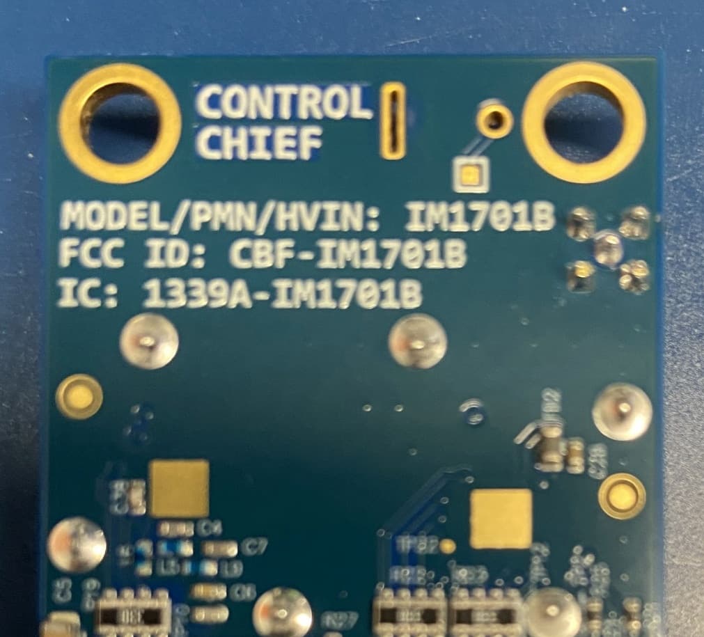
CBF-IM1701B
Jun 22, 2026Battery powered radio
Equipment Class
DSS - Part 15 Spread Spectrum Transmitter
CBF-800R
Feb 07, 2012Wireless Door Opening System, Receiver
Equipment Class
DXT - Part 15 Low Power Transceiver, Rx Verified
CBF-L999
Feb 07, 2012Wireless Door Opening System, Hand Held Controller
Equipment Class
DXT - Part 15 Low Power Transceiver, Rx Verified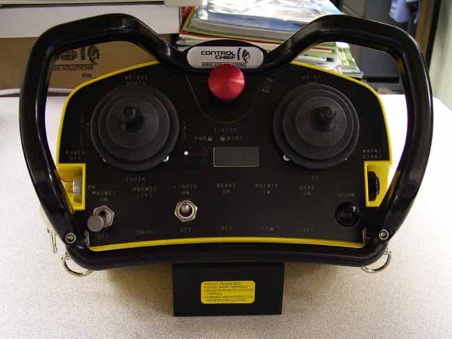
CBF-ADVLJ45-450
May 10, 2008Body Worn Controller
Equipment Class
TNB - Licensed Non-Broadcast Station Transmitter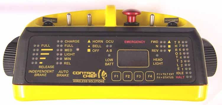
CBF-LTOCU-M
Feb 18, 2006LOCOMOTIVE REMOTE CONTROL SYSTEM
Equipment Class
TNT - Licensed Non-Broadcast Transmitter Worn on Body