CBFFLYMT1-433Remote Control Transmitter
Control Chief Corporation
Click to zoom
Application Details
- Equipment Class
- DSR - Part 15 Remote Control/Security Device Transceiver
- Date of Grant
- Jun 12, 2002
- Application Purpose
- Original Equipment
- Date of Application
- Jun 12, 2002
- Equipment Note
- Remote Control Transmitter
- Frequency Range
- 433.00000000 - 433.00000000
- Company
- Control Chief Corporation
- Country
- United States
Documents & Files
Document Text
Text extracted from the exhibit documents filed with the FCC. Open a document above to read the original.
Users Manual
User’s Guide FlyMa x Trans mi tter The FlyMax transmitter is shipped from the factory fully configured and ready to use. Install Batteries Remove the battery door on the back of the transmitter. Install 2 AA alkaline batteries making sure to ma tc h the polarity marki ng i nside the ba tter y co mpartme nt. Use two new alkaline batteries; do not mix old and new batteries. The transmitter is now ready to use. Depressing any button the transmitter will activate the corresponding function on the receiver. The green indicator located between Throttle Up and Pitch Up button displays the trans mi tter status. Indicator OFFNo buttons depressed transmitter off Indicator FLASHINGTransmitter active Indicator SOLIDReplace batteries IMPORTANT NOTE: This device has been certified to comply with FCC Part 15 rules. Changes or modifications not expressly approved by Control Chief Corporation could void the end user’s authority to operate this equipment
Block Diagram
FlyMax Block Diagram Operator Interface (Pushbuttons) uP Based Encoding Circuit Low Power CPCA Transmitter Antenna
Cover Letter(s)
American Telecommunications Certification Body Inc. 6731 Whittier Ave, McLean, VA 22101 June 10, 2002 RE: FCC ID: CBFFLYMT1-433 Attention: Brian Haghtalab I have a few comments on this Application. 1 Your 731 states that you wish confidentiality, however, no letter requesting confidentiality has been provided. Please provide a letter requesting confidentiality specifically mentioning those parts to be confidential. Remember, only certain items can be held confidential. These include block diagrams, schematics and theories of operation. 2 The users manual contains none of the required FCC statements. Please provide a corrected users manual that contains the statement as required in 15.21 ( Information to user. - The users manual or instruction manual for an intentional or unintentional radiator shall caution the user that changes or modifications not expressly approved by the party responsible for compliance could void the user's authority to operate the equipment). 3 Neither the report nor other documentation give the intent or purpose of this device. Where will this device be used and for what purpose? Dennis Ward mailto:[email protected] The items indicated above must be submitted before processing can continue on the above referenced application. Failure to provide the requested information may result in application termination. Correspondence should be considered part of the permanent submission and may be viewed from the Internet after a Grant of Equipment Authorization is issued. Please do not respond to this correspondence using the email reply button. In order for your response to be processed expeditiously, you must submit your documents through the AmericanTCB.com website. Also, please note that partial responses increase processing time and should not be submitted. Any questions about the content of this correspondence should be directed to the sender.
Cover Letter(s)
Mr. Dennis Ward Examiner Engineer American Telecommunications Certification Body Inc. 6731 Whittier Avenue McLean, VA 22101 RE: Control Chief Low Power FlyMax Transmitter FCC ID: CBFFLYMT1-433 Dear Mr. Ward: This is in reference to the June 10,2002 request for technical information for the above subject project. 1- The revised Form 731 has been uploaded. The customer wishes not file confidentiality for this product. 2- The revised User’s Manual has been uploaded. 3- This device is used to control Concrete Finishing Machine. The transmitter will be worn by the user to transmit commands to the receiver which will activate functions on the receiver installed on the concrete finishing machine. Should you have any concerns or questions, please contact me. Best regards, Brian Haghtalab Operations Manager
ID Label/Location Info
E E E X X X H H H I I I B B B I I I T T T 2 2 2 C C C l l l a a a s s s s s s “ “ “ B B B ” ” ” L L L a a a b b b e e e l l l i i i n n n g g g F F F o o o r r r m m m a a a t t t Label Location (Back View) CONTROL CHIEF FCC ID:CBFFLYMT1-433 This device complies with Part 15 of FCC Rules: Operation is subject to the following two conditions: (1) this device may not cause harmful interference, and (2) this device must accept any interference received, including interference that may cause undesired operation. FCCID LABEL
Operational Description
Operational Description The transmitter as shown by the schematic is a simple microprocessor based device. When a button is pressed, the circuit is powered up and the microprocessor “reads” which button or buttons are depressed. The data is formatted into a serial stream and sent to the radio module which broadcasts the data used a CPCA modulation.
Schematics
/RST R1 267 /RST Q1 PHOTO NPN 1 3 C2 0.1 uF VCC D1 LED U4 LC RF TX 1 2 3 45 6 7 8 GND DATA GND IADJRF OUT GND Vcc GND PB2 PUSHBUTTON DPST 12 34 C1 0.1 uF VCC J3 CON1 1 F1 FUSE U1 NC7S08 1 2 34 5 Two 1.5V cells PB1 PUSHBUTTON DPST 12 34 Y1 4.00 MHz 13 2 VCC GND /RST/MR Vcc U3 MAX811 1 23 4 VCC U2 AT90S1200 1 4 5 20 12 13 14 15 16 17 18 19 2 3 6 7 8 9 11 RESET XTAL2 XTAL1 VCC PB0/AIN0 PB1/AIN1 PB2 PB3 PB4 PB5/MOSI PB6/MISO PB7/SCK PD0 PD1 PD2/INTO PD3 PD4/TO PD5 PD6 VCC PB5 PUSHBUTTON DPST 12 34 D2 DIODE 1 2 VCC R2 10K PB4 PUSHBUTTON DPST 12 34 PB3 PUSHBUTTON DPST 12 34 VCC ANT1 SPLATCH ANT 123456 RF INGNDGNDGNDGNDGND VCC J2 CON1 1 VCC VCC J1 CON8 1 2 3 4 5 6 7 8
Test Report
C C O O N N T T R R O O L L C C H H I I E E F F F F C C C C I I N N F F O O R R M M A A T T I I O O N N FLYMAX Remote Control TransmitterPage 2 of 22 R R R F F F M M M e e e a a a s s s u u u r r r e e e m m m e e e n n n t t t R R R e e e p p p o o o r r r t t t P P P r r r e e e p p p a a a r r r e e e d d d b b b y y y : : : N N N a a a t t t i i i o o o n n n a a a l l l C C C e e e r r r t t t i i i f f f i i i c c c a a a t t t i i i o o o n n n L L L a a a b b b o o o r r r a a a t t t o o o r r r y y y 8370 Court Avenue, Suite B-1 Ellicott City, Maryland 21043 (410) 461-5548 I I I n n n S S S u u u p p p p p p o o o r r r t t t o o o f f f : : : F F F o o o r r r : : : Control Chief 200 Williams Street Bradford, PA 16701 Model: FLYMAX Remote Control Transmitter FCCID: CBFFLYMT1-433 Demonstration of Compliance with FCC Rules Part 15.231 No part of this report may be reproduced without written approval of National Certification Laboratory May 26, 2002 FCC CERTIFICATION FLYMAX Remote Control TransmitterPage 3 of 22 TABLE OF CONTENTS 1.0General Information.................................................................................................................................4 1.1...Summary..............................................................................................................4 1.2...Test Methodology...................................................................................................................................4 1.3...Test Facility.............................................................................................................................................4 2.0Description of Equipment Under Test (EUT).........................................................................................5 2.1...EMI Countermeasure..............................................................................................................................6 3.0Test Program ............................................................................................................................................6 4.0Test Configuration for Radiated and Conducted Emissions................................................................6 4.1...Bandwidth Emission Test Result............................................................................................................7 4.1.1Bandwidth Emission Plot................................................................................................................8 4.2.1Peak Field Strength of Fundamental Plot........................................................................................9 5.0Conducted Emissions Scheme................................................................................................................10 6.0Radiated Emissions Scheme...................................................................................................................11 6.1...Radiated Emissions Data Table.............................................................................................................13 TABLES Table 1EUT Accessories..............................................................................................................14 Table 2Support Equipment.........................................................................................................15 Table 3Measurement Equipment Used......................................................................................16 EXHIBITS Photographs NCL PROJ.# Control-0725 FLYMAX Remote Control TransmitterPage 4 of 22 1.0 General Information: This report has been prepared on behalf of Control Chief, to support the FCC Certification of a Part 15 Intentional Radiator. The Equipment Under Test (EUT) was the Model: FLYMAX Remote Control Transmitter. The EUT configuration consisted of one Transmitter and one Receiver unit. The test results reported in this document relate only to the item that was tested. Radio-Noise Emissions tests were performed according to the ANSI C63.4- 1992, “Method of Measurement of RFI from Low-Voltage Electronic Equipment in the Range of 9 KHz- 40 GHz”. The measuring equipment conforms to ANSI C63.2 Specifications for electromagnetic Noise and Field Strength-Instrumentation 1.1 Summary: The Control Chief, Model: FLYMAX Remote Control Transmitter, complies with the Part 15.231 Radio Limits for periodic operation above 70 MHz for an Intentional Radiator.. 1.2 Test Methodology; Both conducted and radiated testing were performed according to the procedures in ANSI C63.4 1992. Radiated testing was performed at an antenna to EUT distance of three (3) meters. 1.3 Test Facility: The open area test site and conducted measurement facility used to collect the radiated data is located on the parking lot of National Certification Laboratory 8370 Court Avenue, Suite B-1, Ellicott City, Maryland 21043. This site has been fully described in a report dated May 26, 1993, submitted to and approved by the Federal Communications Commission to perform AC line conducted and radiated emissions testing. FLYMAX Remote Control TransmitterPage 5 of 22 2.0 Description of Equipment Under Test (EUT): The EUT features: I I I n n n t t t e e e r r r n n n a a a l l l P P P C C C B B B m m m o o o u u u n n n t t t A A A n n n t t t e e e n n n n n n a a a 4 4 4 3 3 3 3 3 3 M M M H H H z z z F F F r r r e e e q q q u u u e e e n n n c c c y y y T T T r r r a a a n n n s s s m m m i i i t t t t t t e e e r r r C C C h h h i i i p p p D D D e e e s s s i i i g g g n n n B B B S S S K K K M M M o o o d d d u u u l l l a a a t t t i i i o o o n n n M M M a a a n n n u u u a a a l l l p p p u u u s s s h h h “ “ “ O O O N N N ” ” ” w w w i i i t t t h h h i i i m m m m m m e e e d d d i i i a a a t t t e e e “ “ “ O O O F F F F F F ” ” ” u u u p p p o o o n n n r r r e e e l l l e e e a a a s s s e e e B B B a a a t t t t t t e e e r r r y y y O O O p p p e e e r r r a a a t t t i i i o o o n n n FLYMAX Remote Control Trans…
Text truncated - open the document above for the full version.
Contact Information
Applicant
Jake Bryner(VP Product Design & Development)
Technical Contact
National Certification LaboratoryBrian Haghtalab
[email protected]410-461-5548
8370 Court Avenue · Ellicott City, Maryland · United States
Non-Technical Contact
National Certification LaboratoryBrian Haghtalab
[email protected]410-461-5548
Test Firm
National Certification LaboratoryBrian Haghtalab
Technical Specifications
| # | Rule Parts | Frequency Range | Power Output |
|---|---|---|---|
| 1 | 15C | 433 MHz - 433 MHz | - |
Other Applications from Control Chief Corporation
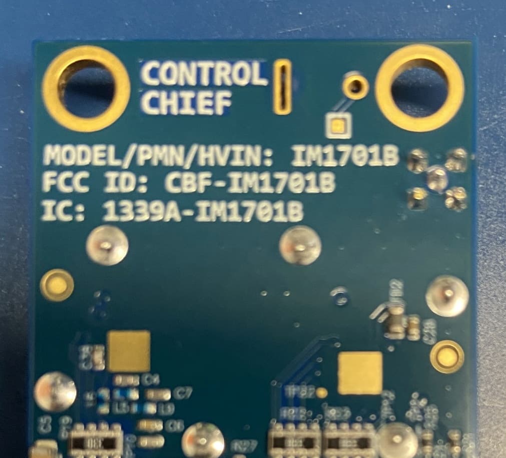
CBF-IM1701B
Jun 22, 2026Battery powered radio
Equipment Class
DSS - Part 15 Spread Spectrum Transmitter
CBF-800R
Feb 07, 2012Wireless Door Opening System, Receiver
Equipment Class
DXT - Part 15 Low Power Transceiver, Rx Verified
CBF-L999
Feb 07, 2012Wireless Door Opening System, Hand Held Controller
Equipment Class
DXT - Part 15 Low Power Transceiver, Rx Verified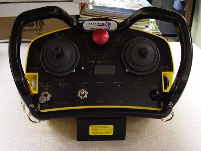
CBF-ADVLJ45-450
May 10, 2008Body Worn Controller
Equipment Class
TNB - Licensed Non-Broadcast Station Transmitter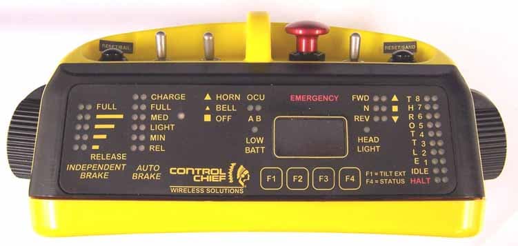
CBF-LTOCU-M
Feb 18, 2006LOCOMOTIVE REMOTE CONTROL SYSTEM
Equipment Class
TNT - Licensed Non-Broadcast Transmitter Worn on Body