CCKPC0086RFID READER FOR ALARM SYSTEM KEYPAD
Digital Monitoring Products Inc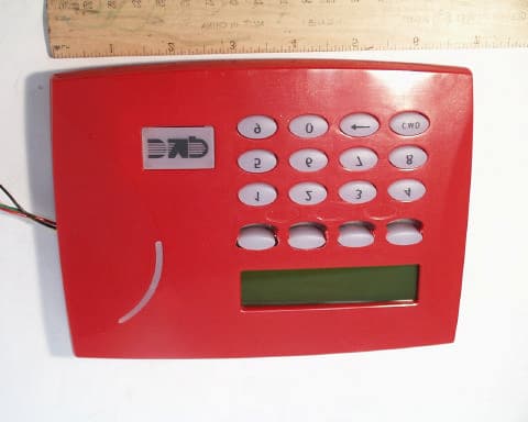
Click to zoom
Application Details
- Equipment Class
- DCD - Part 15 Low Power Transmitter Below 1705 kHz
- Date of Grant
- Aug 25, 2004
- Application Purpose
- Original Equipment
- Date of Application
- Aug 25, 2004
- Equipment Note
- RFID READER FOR ALARM SYSTEM KEYPAD
- Frequency Range
- 0.12500000 - 0.12500000
- Country
- United States
Documents & Files
Document Text
Text extracted from the exhibit documents filed with the FCC. Open a document above to read the original.
Users Manual
INSTALLATION SHEET 7000 Series Thinline LCD Keypads Models 7060/7064/7070/7075 Description The DMP 7000 Series Thinline LCD Keypads offer the same flexible features and functionality as current DMP keypads in a stylish, sleek new design. Each keypad provides four 2-button Panic keys, an AC power LED, an Armed LED, 32-character display, backlit logo and keyboard with easy-to-read lettering and an internal speaker. The 7070 and 7075 keypads provide four fully programmable Class B, Style A protection zones you can program for a variety of burglary, fire, and access control applications. The 7064 and 7075 keypads provide a built-in proximity card reader specifically designed to accept DMP 1400 Series proximity credentials. The Model 7075 also allows connection of any Weigand output reader. Installing the Keypad The keypad housing is designed to easily install on any 4” square box, 3-gang switch box, 695 and 696 backbox, or flat surface. Figure 1 shows the keypad housing mounting hole locations. Removing the Base The keypad housing is made up of two parts: the front, which contains the circuit board, keyboard components, and the base. To mount the keypad, remove the base from the front by inserting a flat screwdriver into one of the openings on the bottom. Twist the screwdriver while pulling the halves apart. Repeat with the other opening. Harness Wiring Figure 1 shows wiring harness assignments. Observe wire colors when connecting the red, yellow, green, and black wires to the keypad bus. When wiring directly to the panel terminals, connect red to panel terminal 7, yellow to terminal 8, green to 9, and black to panel terminal 10. Use 1k Ohm EOL resistors, DMP Model 311, on keypad zones 1 through 4. The 7060 and 7064 keypads are supplied with a 4-wire harness for panel keypad bus connection. The 7070 and 7075 keypads are supplied with a 12-wire data bus/zone harness. Four wires connect to the keypad bus, the same way the 7060 and 7064 keypad harness connects. The remaining eight wires are for the four zone inputs: two wires for each zone. The 7075 keypad is also supplied with one 5-wire output/reader harness. Surface and Backbox Mounting Holes Combined 4-square and 3-gang switch box Mounting Holes Keypad Back Surface and Backbox Mounting Holes 1K EOL 1K EOL 1K EOL 1K EOL Green/White – Connect Reader Data 0 Whit e – Connect Reader Data 1 Orange – Door Strike Normally Open Gray – Door Strike Common Violet – Door Strike Normally Closed Yellow/Whit e White/Yello w Orange White White/Orange Red/White White/Re d Brown/White White/Brow n Black – Ground Green – Receive Data Yellow – Send Data Red – Keypad Power – Zone 4 – Zone 3 – Zone 2 – Zone 1 Output Reader 7075 Keypad Zones 1 through 4 7070 and 7075 Keypads All Keypads Figure 1: Keypad Back Showing Wiring Harness Assignments Digital Monitoring Products 7000 Series Keypad Installation Sheet 2 7000 Series Keypad Installation Sheet Digital Monitoring Products 3 Wiring Specifications When planning a keypad bus installation, keep in mind the following specifications: 1. DMP recommends using 18 or 22-gauge unshielded wire for all keypad and LX-Bus circuits. Do Not use twisted pair or shielded wire for LX-Bus and keypad bus data circuits. To maintain auxiliary power integrity when using 22-gauge wire do not exceed 500 feet. When using 18-gauge wire do not exceed 1,000 feet. Install an additional power supply to increase the wire length or add devices. 2. Maximum distance for any one circuit (length of wire) is 2,500 feet regardless of the wire gauge. This distance can be in the form of one long wire run or multiple branches with all wiring totaling no more than 2,500 feet. As wire distance from the panel increases, DC voltage on the wire decreases. 3. Maximum number of devices per 2,500 feet circuit is 40. Note: Each panel allows a specific number of supervised keypads. Add additional keypads in the unsupervised mode. Refer to the panel installation guide for the specific number of supervised keypads allowed. 4. Maximum voltage drop between the panel (or auxiliary power supply) and any device is 2.0 VDC. If the voltage at any device is less than the required level, add an auxiliary power supply at the end of the circuit. When voltage is too low, the devices cannot operate properly. Refer to the 710/710F Module Installation Sheet (LT-0310) for more information. Also see the LX-Bus/Keypad Bus Wiring Application Note (LT-2031). Additional Power Supply If the current draw for all keypads exceeds the panel output, you can provide additional current by adding a Model 505-12 auxiliary power supply. Connect all keypad common wires to the power supply negative terminal. Run a jumper wire from the power supply negative terminal to the panel common terminal. Connect all keypad power (+12 VDC) wires to the power supply positive terminal. Do NOT connect the power supply positive terminal to any panel terminal. Refer to the 504-24 and 505-12 Power Supply Installation Guide (LT-0453) for more information. Wiring a 12 VDC Access Control Reader on 7075 keypads To use 12 VDC readers with the 7075 keypad, connect the Red and Black power wires from the reader to the power wires from the panel. These connect in parallel with the keypad power wires. Connect the White data wire from the reader (Data 1) to the White wire on the 5-wire keypad harness. Connect the Green data wire from the reader (Data 0) to the Green/White wire on the 5-wire keypad harness. 1K EOL 1K EOL 1K EOL 1K EOL Green/White – Connect Reader Data 0 White – Connect Reader Data 1 Orange – Door Strike Normally Open Gray – Door Strike Common Violet – Door Strike Normally Closed Yellow/White White/Yello w Orange White White/Orange Red/White White/Re d Brown/White White/Brow n Blac k – Ground Green – Receive Data Yellow – Send Data Red – Keypad Power – Zone 4 – Zone 3 Request to Exit (option) – Zone 2 Door Contact (option) – Zone 1 7/0 Panic (option) To Keypad Bus Card Reade r Figure 2: 12 VDC Reader Wiring for 7…
Text truncated - open the document above for the full version.
Cover Letter(s)
August 18, 2004 Timco Engineering Inc. 849 NW State Road 45 Newberry, FL 32669 Applicant: Digital Monitoring Products, Inc. 2500 N. Partnership Boulevard Springfield, MO 65802 Re: Confidentiality for submittal information regarding FCC ID number CCK PC0086 PRODUCT: RFID Keypad for alarm system operating at 0.125 MHz frequency under part 15.209 Dear Sirs: Digital Monitoring Products, Inc. requests that the material in the Block diagram, Schematics, and Operational Description be withheld from public disclosure in accordance with Section 0.459 of the Commissions Rules, 47 C.F.R. 0.459 (1998), following grant of the application. In support of this request, Digital Monitoring Products, Inc. submits the following: 1. Identification of the specific information for which confidential treatment is sought: The materials set fourth in the Operational Description, Block Diagram, and Schematics, which are segregated from the non-confidential exhibits of the application, are those for which confidentiality is sought. 2. Identification of the Commission proceeding in which the information was submitted or a description of the circumstances giving rise to the submission: The proceeding is that involving the application for equipment authorization (certification) under FCC ID No: CCK PC0086 3. Explanation of the degree to which the information is commercial or financial, or contains a trade secret or is privileged: This material includes a detailed theory of operation and circuit diagrams, (schematic, and block diagrams). As such, this material is treated as highly confidential business information. ROGERS LABS, INC. 4405 West 259 th Terrace Louisburg, KS 66053 4. Explanation of the degree to which the information concerns a service that is subject to competition: The material for which confidentiality is sought is employed in the design and manufacture of this low power transmitting equipment that is offered on a highly competitive basis. Customers for this equipment have a variety of competing sources. 5. Explanation of how disclosure of the information could result in substantial competitive harm: Disclosure would, in effect, give away the fruits of the labors of Digital Monitoring Products, Inc.’s engineering personnel, who have designed the equipment and the manufacturing process. Disclosure would also offer competitors additional unwarranted insight into the state of the product development, thereby allowing competitors an advantage, not available to Digital Monitoring Products, Inc. 6. Identification of any measures taken by the submitting party to prevent unauthorized disclosure: The information for which confidential treatment is sought is kept confidential by Digital Monitoring Products, Inc. and not made available to third parties except pursuant to non-disclosure agreements. 7. Identification of whether the information is available to the public and the extent of any previous disclosure of the information to third parties: To the knowledge of those preparing this application, the information has not been disclosed publicly heretofore. While the general theory of operation of this equipment has been the subject of numerous disclosures in industry and standards groups as well as in rule making proceedings of the FCC, the protection sought is narrowly drawn and pertains to certain specific implementations of the low power radio technology. 8. Justification of the period during which the submitting party asserts that the material should not be available for public disclosure: This material should not be disclosed for at least 25 years. While improvements in design are made relatively frequently, disclosure of the design information would lead to insights into both design and manufacturing techniques that could have an adverse competitive effect for many years to come. This equipment is designed for residential, commercial, industrial, and governmental applications. As such, it is important that the design not be made available to unauthorized persons who might attempt to use knowledge of the design to compromise the applications for which the equipment will be employed. 9. Any other information that the party seeking confidential treatment believes may be useful in assessing whether its request for confidentiality should be granted: See item 8 above. Note that the equipment for which approval is being sought will be employed in applications that inherently place a premium on security. Should you require any further information, please contact the undersigned. Thank you for your consideration in this matter. Sincerely, Scot Rogers
External Photos
ROGERS LABS, INC. Digital Monitoring Products, Inc. 4405 W. 259th Terrace MODEL: PC0086 Keypad Louisburg, KS 66053 Test #: 040727 FCC ID#: CCK PC0086 Phone/Fax: (913) 837-3214 Test to: FCC Parts 2 and 15C Page 1 of 1 DMP PC0086 KeypadExtPho 8/17/04 External Photos of PC0086 Keypad.
ID Label/Location Info
ROGERS LABS, INC. Digital Monitoring Products, Inc. 4405 W. 259th Terrace MODEL: PC0088 Keypad Louisburg, KS 66053 Test #: 040727 FCC ID#: CCK Pc0086 Phone/Fax: (913) 837-3214 Test to: FCC Parts 2 and 15C Page 1 of 1 DMP PC0086 KeypadLabel 8/17/04 FCC ID label and location for PC0086 Keypad. ID label is 0.25 inches high by 0.75 inches wide.
Internal Photos
ROGERS LABS, INC. Digital Monitoring Products, Inc. 4405 W. 259th Terrace MODEL: PC0086 Keypad Louisburg, KS 66053 Test #: 040727 FCC ID#: CCk PC0086 Phone/Fax: (913) 837-3214 Test to: FCC Parts 2 and 15C Page 1 of 1 DMP PC0086 KeypadIntPho.doc 8/17/04 Internal Photographs of PC0086 Keypad.
Test Report
ENGINEERING TEST REPORT FOR APLLICATION of GRANT of CERTIFICATION FOR CFR 47, PART 15C - INTENTIONAL RADIATORS Paragraph 15.209 Radiated emission limits; general requirements For DIGITAL MONITORING PRODUCTS, INC. 2500 North Partnership Boulevard Springfield, MO 65802-6310 Terry Shelton, RFID READER Model: PC0086 ThinLine Keypad Frequency 0.125 MHz FCC ID#: CCK PC0086 Test Date: August 12, 2004 Certifying Engineer: Scot D. Rogers ROGERS LABS, INC. 4405 West 259 th Terrace Louisburg, KS 66053 Phone: (913) 837-3214 FAX: (913) 837-3214 This report shall not be reproduced except in full, without the written approval of the laboratory. This report must not be used by the client to claim product endorsement by NVLAP or any agency of the U.S. Government. ROGERS LABS, INC. 4405 West 259 th Terrace Louisburg, KS 66053 Phone / Fax (913) 837-3214 NVLAP Accredited Laboratory NVLAP Lab Code: 200087-0 ROGERS LABS, INC. Digital Monitoring Products, Inc. 4405 W. 259th Terrace MODEL: PC0086 ThinLine Keypad Louisburg, KS 66053 Test #: 040727 FCC ID#: CCK PC0086 Phone/Fax: (913) 837-3214 Test to: FCC Parts 2 and 15c (15.209) Page 2 of 27 DMP PC0086 Keypad TstRpt.doc 8/18/2004 TABLE OF CONTENTS FORWARD:.....................................................................................................................3 1) APPLICABLE STANDARDS & TEST PROCEDURES...........................................3 2.1033(b) Application for Certification....................................................................................................4 2) EQUIPMENT TESTED.............................................................................................5 3) EQUIPMENT FUNCTION AND TESTING PROCEDURES.....................................5 4) EQUIPMENT AND CABLE CONFIGURATIONS.....................................................6 Conducted Emission Test Procedure............................................................................................................6 Radiated Emission Test Procedure:.............................................................................................................6 5) LIST OF TEST EQUIPMENT...................................................................................7 6) UNITS OF MEASUREMENTS.................................................................................7 7) TEST SITE LOCATIONS.........................................................................................8 8) SUBPART B – UNINTENTIONAL RADIATORS.....................................................8 Conducted EMI.............................................................................................................................................8 Radiated EMI..............................................................................................................................................10 Conducted (7 Highest Emissions)...............................................................................................................12 Data: General Radiated Emissions from test system (6 Highest Emissions)................................................13 Summary of Results for Test System Conducted Emissions......................................................................13 Summary of Results for Test System Radiated Emissions.........................................................................13 Statement of Modifications and Deviations................................................................................................13 9) SUBPART C - INTENTIONAL RADIATORS.........................................................14 15.203 Antenna Requirements....................................................................................................................14 15.205 Restricted Bands of Operation........................................................................................................14 Data: Emissions in Restricted Bands from EUT and support Equipment.....................................................14 Summary of Results for Radiated Emissions in Restricted Bands:...........................................................15 15.209 Radiated Emissions Limits; General Requirements.......................................................................15 Radiated EMI.............................................................................................................................................15 Data: General Radiated Emissions from EUT (6 Highest Emissions).........................................................19 Summary of Results for Radiated Emissions:............................................................................................19 Radiated Emissions of Intentional Radiator in the Band 0.125 MHz........................................................19 Data: Radiated Emissions data from EUT taken at three meter distance......................................................21 Summary of Results for Radiated Emissions of Intentional Radiator.......................................................22 Statement of Modifications and Deviations................................................................................................22 NVLAP Accredited Laboratory NVLAP Lab Code: 200087-0 ROGERS LABS, INC. Digital Monitoring Products, Inc. 4405 W. 259th Terrace MODEL: PC0086 ThinLine Keypad Louisburg, KS 66053 Test #: 040727 FCC ID#: CCK PC0086 Phone/Fax: (913) 837-3214 Test to: FCC Parts 2 and 15c (15.209) Page 3 of 27 DMP PC0086 Keypad TstRpt.doc 8/18/2004 FORWARD: The following is submitted for consideration in obtaining a Grant of Certification for intentional radiators operating under CFR Paragraph 15.209. Name of Applicant: DIGITAL MONITORING PRODUCTS, Inc. 2500 North Partnership Boulevard Springfield, MO 65802-6310 Model: PC0086 ThinLine Keypad. FCC I.D.: CCK PC0086. Frequency Range: 0.125 MHz. Operating Power: 7.4E-6 W (3 meter effective radiated power calculation). 1) Applicable Standards & Test Procedure…
Text truncated - open the document above for the full version.
Contact Information
Applicant
Brad Tucker(VP - Product Management and Support)
Test Firm
Rogers Labs, Inc.Scot Rogers
Technical Specifications
| # | Rule Parts | Frequency Range | Power Output |
|---|---|---|---|
| 1 | 15C | 0.125 MHz - 0.125 MHz | - |
Other Applications from Digital Monitoring Products Inc
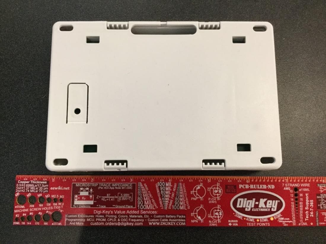
CCKPC0245
Apr 23, 20231101 Receiver
Equipment Class
DSS - Part 15 Spread Spectrum Transmitter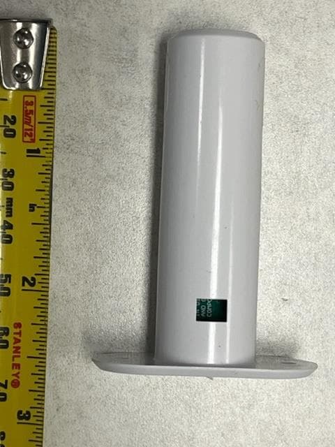
CCKPC0241
Dec 29, 20221132 Recessed contact
Equipment Class
DSS - Part 15 Spread Spectrum Transmitter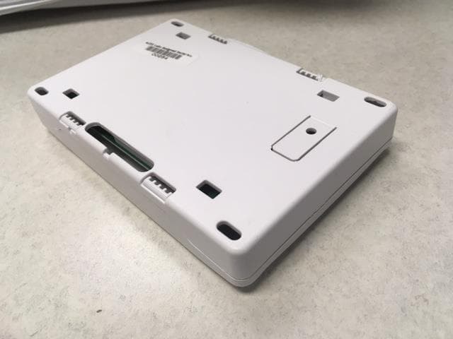
CCKPC0114R9
May 10, 2021Life Safety and security wireless receiver.
Equipment Class
DSS - Part 15 Spread Spectrum Transmitter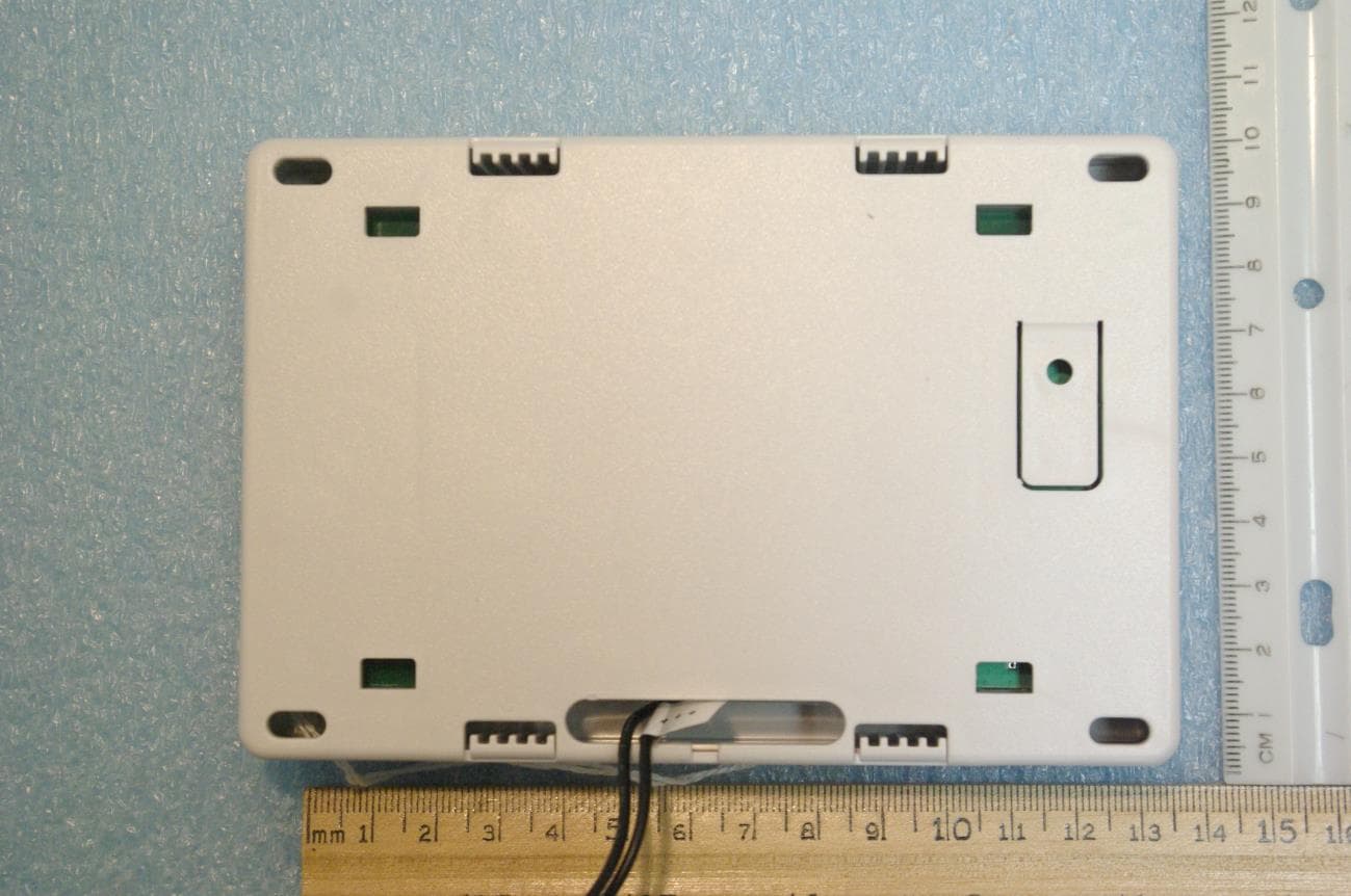
CCKPC0225
Jan 06, 2021900 MHz FHSS Transceiver System
Equipment Class
DSS - Part 15 Spread Spectrum Transmitter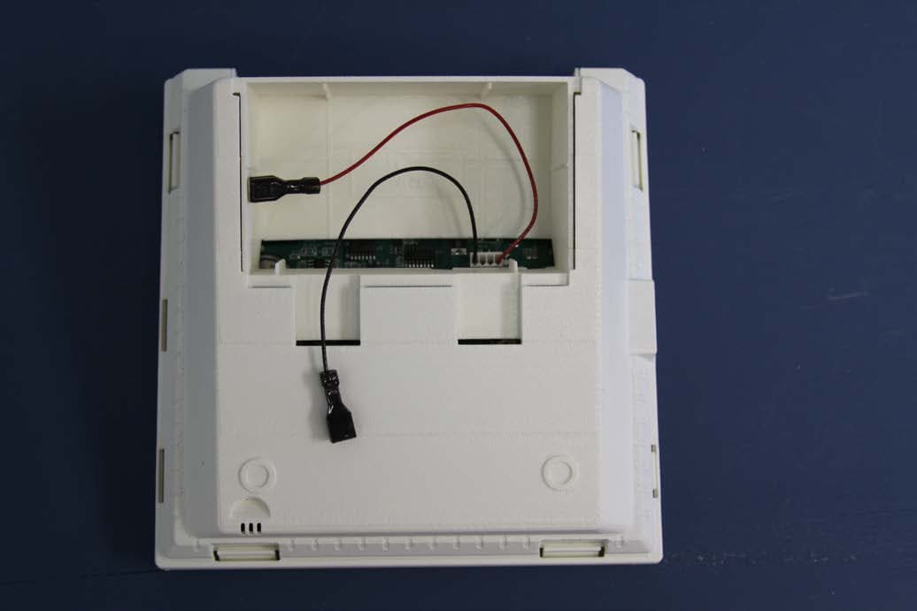
CCKPC0156
Oct 21, 2015Personal Emergency Response Base Unit
Equipment Class
DXX - Part 15 Low Power Communication Device Transmitter