CCKPC0225900 MHz FHSS Transceiver System
Digital Monitoring Products Inc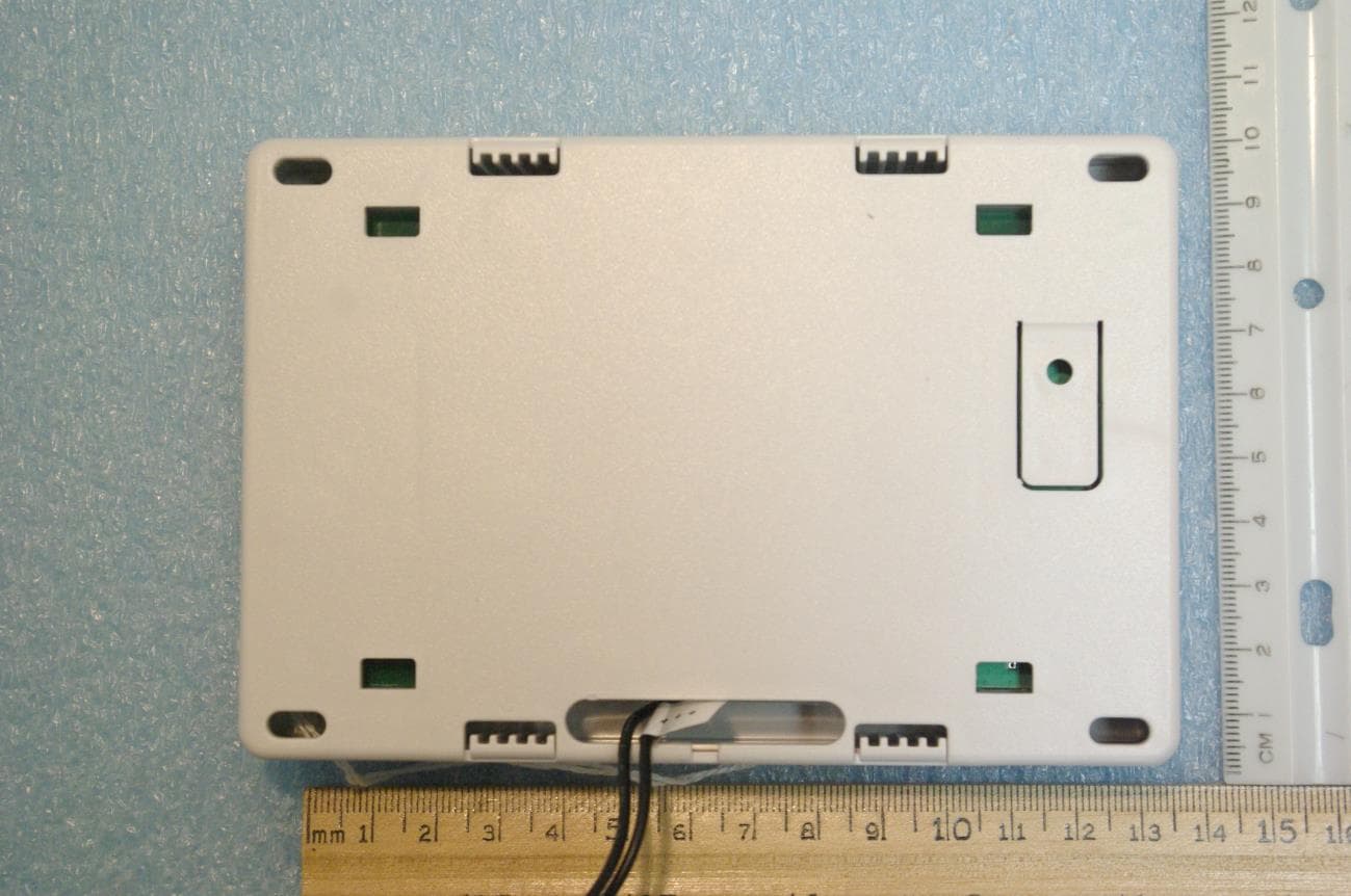
Click to zoom
Application Details
- Equipment Class
- DSS - Part 15 Spread Spectrum Transmitter
- Date of Grant
- Jan 06, 2021
- Application Purpose
- Original Equipment
- Date of Application
- Jan 06, 2021
- Equipment Note
- 900 MHz FHSS Transceiver System
- Frequency Range
- 905.60000000 - 924.40000000
- Country
- United States
Documents & Files
Document Text
Text extracted from the exhibit documents filed with the FCC. Open a document above to read the original.
Users Manual
1100T WIRELESS TRANSLATOR Installation Guide DESCRIPTION The 1100T Wireless Translator allows upgrades of non-DMP systems with one-way, low frequency, wireless transmitters to DMP. The 1100T is compatible with transmitters that operate at various MHz such as Interlogix, Honeywell 5800, 2GIG, and DSC. The translator operates with a wireless connection to a DMP panel. Transmitters that have been learned into the 1100T are able to send supervision and low battery messages to the panel. Compatibility • All DMP XT Series panels and XR Series panels with version 203 or higher • All 1100 Series Wireless Receivers with version ???? or higher • Interlogix 319.5 MHz • Honeywell 5800 345 MHz • 2GIG Series 345 MHz • DSC 433 MHz Note: The 1100T is not compatible with life safety devices. What is Included? • 1100T Wireless Translator • 12 VDC Power Supply • Hardware Pack 1 PROGRAM THE PANEL Because the 1100T is a wireless device, all panel programming must be completed in Device Setup and zones should be programmed in Zone Information. For XR Series Panels Device Setup 1. Enter 6653 (PROG) at the keypad. 2. Press CMD and select DEVICE SETUP. 3. At DEVICE TYPE, press CMD to display options. 4. Press CMD again to open the extended options menu. 5. Select 1100T and press CMD to save. 6. Enter the Serial number. 7. At 1100T FREQ, select any select key or area to select the non-DMP system. Default is HWL (Honeywell). 8. Press CMD. Zone Information 1. In ZONE INFORMATION, enter the wireless zone number. 2. At *UNUSED*, enter the zone name. 3. Select a ZONE TYPE. 4. At DMP WIRELESS, select NO. 5. At COMP WLS, select YES. 6. At COMP WLS SRL #, you can manually enter the serial number of the transmitter or transmit the serial number to the panel: Manually: Press top row key 1 and then begin typing the transmitters serial number. Transmit: To transmit the serial number, choose LRN at prompt to display TRANSMIT NOW. Tamper the transmitter. Once the panel has received the tamper signal, the serial number will display. 7. Press CMD. For XT Series Panels Device Setup 1. Enter 6653 (PROG) at the keypad. 2. Press CMD and select DEVICE SETUP. 3. At 1100T? NO YES, select YES and press CMD. 4. Enter the Serial number. 5. At 1100T FREQ select any select key or area to select the non-DMP system. Default is HWL. 6. Press CMD. Zone Information 1. In ZONE INFORMATION, enter the wireless zone number. 2. At *UNUSED*, enter the zone name. 3. Select a ZONE TYPE. 4. At DMP WIRELESS select NO. 5. At COMP WLS select YES. 6. At COMP WLS SRL #, see Step 6 from the XR Zone Information section above. 7. Press CMD. 2 1100T INSTALLATION GUIDE | DIGITAL MONITORING PRODUCTS 3 The 1100T translator provides a Survey LED capability to allow one person to confirm communication with the panel while the cover is removed. 1. With the cover removed, hold the translator in the exact desired location. 2. Press the tamper switch to send data to the panel and determine if communication is confirmed or faulty. Confirmed: If communication is confirmed, for each press or release of the tamper switch, the LED blinks immediately on and immediately off. Repeat this test 5 times to confirm ten separate consecutive LED blinks. Any indication otherwise means proper communication has not been established. Faulty: If communication is faulty, the LED remains on for about 8 seconds or flashes multiple times in quick succession. Relocate the translator or receiver until the LED confirms clear communication. SELECT A LOCATION MOUNT THE TRANSLATOR The translator must be mounted using the provided #6 screws in the four mounting holes. Mount the translator in a secure, dry place away from metal objects to protect the panel from damage due to tampering or the elements. Mount the translator a minimum of 4 feet from any wireless panels or repeaters. It is not necessary to remove the PCB when installing the enclosure. 4 POWER THE TRANSLATOR 2 Wire the Power Supply The 1100T can be powered from a 12 VDC external power supply. In addition to powering the 1100T, the power supply also charges the back-up battery. If the DC power source is removed, the power failure is indicated as an open condition on the 1100T zone. The 372-500-W must be located within 100 feet of the panel using 22 AWG wire. Use the following steps to connect the model 372-500-W plug-in DC power supply to the 1100T: 1. Connect the positive wire to the positive terminal on the 1100T. 2. Connect the negative wire to the negative terminal on the 1100T. 3. Plug the power supply into a wall outlet not controlled by a switch. Mounting Hole Locations +BAT-+12V- - + 1100T INSTALLATION GUIDE | DIGITAL MONITORING PRODUCTS 3 ADDITIONAL INFORMATION Replace the Battery 1. Open the translator housing to expose the inside of the 1100T. 2. Remove the PCB board 3. Unplug the battery connector, then remove the old battery 4. Place the new battery in the holder. 5. Connect the battery connector 6. Snap the PCB Board back in place. 7. Snap the cover back on the 1100T. Designed, engineered, and manufactured in Springfield, MO using U.S. and global components. LT-2243 1.01 20XXX 1100T WIRELESS TRANSLATOR Specifications Operating Voltage XX VDC, XX mA Standby Battery Voltage 3.7 VDC Capacity 800 mAh Type Lithium Polymer, rechargeable Standby 24 hours Frequency Range 905-924 MHz Dimensions 5.50” W x 3.75” H x 1.00” D 13.97cm W x 9.53 cm H x 2.54 cm D Ordering Information 1100T Wireless Translator Patents U.S Patent No. 7,239,236 Accessories 1100RBAT800/8 Replacement rechargable battery (8 pack) 505-12 12 VDC Power Supply 372-500-W Plug-In DC Power Supply Compatibility All DMP XT Series panels and XR Series panels with version 203 or higher All 1100 Series Wireless Receivers with version ????? or higher Interlogix 319.5 MHz Honeywell 5800 345 MHz 2GIG Series 345 MHz DSC 433 MHz Certifications ????????????????????????? INTRUSION • FIRE • ACCESS • NETWORKS 2500 North Partnership Boulevard Springfield, Missouri 65803-8877 800.641.4282 …
Text truncated - open the document above for the full version.
Cover Letter(s)
Page 1 of 2 December 11, 2020 Timco Engineering Inc. 849 NW State Road 45 Newberry, FL 32669 Applicant: Digital Monitoring Products 2500 North Partnership Boulevard Springfield, MO 65802 Re: Confidentiality for submittal information regarding FCC ID: CCKPC0225 Product: Transmitter operated under 47CFR Section 15C Dear Sirs: Digital Monitoring Products requests that the material in the Block Diagram, Operational Description, Schematics, and Tune up Procedure be withheld from public disclosure pursuant to Sections 0.457 and 0.459 of the Commission’s Rules following grant of the application. In support of this request, Digital Monitoring Products submits the following information. CONFIDENTIAL FILES 1100T Conf BlkDia.pdf 1100T Conf OpDes.pdf 1100T Conf OpDes1.pdf 1100T Conf Schem.pdf 1100T Conf TunPro.pdf 1. Identification of the specific information for which confidential treatment is sought: The materials set forth in the Block Diagram, Operational Description, Schematics, and Tune up Procedure which are segregated, from the non-confidential exhibits of the application, are those for which confidentiality is sought. 2. Identification of the Commission proceeding in which the information was submitted or a description of the circumstances giving rise to the submission: The proceeding is that involving the application for equipment authorization (certification) under FCC ID: CCKPC0225 3. Explanation of the degree to which the information is commercial or financial, or contains a trade secret or is privileged: This material includes a detailed Block Diagram, Operational Description, Schematics, and Tune up Procedure. As such, this material is treated as highly confidential business information. ROGERS LABS, INC. 4405 West 259 th Terrace Louisburg, KS 66053 913 837-3214 Page 2 of 2 4. Explanation of the degree to which the information concerns a service that is subject to competition: The material for which confidentiality is sought is employed in the design and manufacture of this transmitting equipment that is offered on a highly competitive basis. Customers for this equipment have a variety of competing sources. 5. Explanation of how disclosure of the information could result in substantial competitive harm: Disclosure would, in effect, give away the fruits of the labors of Digital Monitoring Products’s engineering personnel, who have designed the equipment and the manufacturing process. Disclosure would also offer competitors additional unwarranted insight into the state of the product development, thereby allowing competitors an advantage, not available to Digital Monitoring Products 6. Identification of any measures taken by the submitting party to prevent unauthorized disclosure: The information for which confidential treatment is sought is kept confidential by Digital Monitoring Products and not made available to third parties except pursuant to non-disclosure agreements. 7. Identification of whether the information is available to the public and the extent of any previous disclosure of the information to third parties: To the knowledge of those preparing this application, the information has not been disclosed publicly heretofore. While the general theory of operation of this equipment has been the subject of numerous disclosures in industry the protection sought is narrowly drawn as provided in regulations. 8. Justification of the period during which the submitting party asserts that the material should not be available for public disclosure: This material should not be disclosed for at least 25 years. While improvements in design are made relatively frequently, disclosure of the design information would lead to insights into both design and manufacturing techniques that could have an adverse competitive effect for many years to come. As such, it is important that the design not be made available to unauthorized persons who might attempt to use knowledge of the design to compromise the applications for which the equipment will be employed. Should you require any further information, please contact the undersigned. Thank you for your consideration in this matter. Sincerely, Scot Rogers
Cover Letter(s)
December 22, 2020 Federal Communications Commission Authorization and Evaluation Division 1435 Oakland Mills Rd Columbia MD 21046 To Whom It May Concern: Regarding CCKPC0225 label placement for this application, Digital Monitoring Products wishes to print the information directly onto the device circuit board. This location will ensure the end user is always able to view the information before operation. The identifier will be readily viewable upon installation and each time the cover is removed. Printing the identifier in this location will help ensure the longevity of the label as this equipment may be in service in harsh environments. If you have any questions or comments, please do not hesitate to contact me. Best regards, Brad Tucker VP - Product Management & Support Digital Monitoring Products, Inc.
Cover Letter(s)
December 10, 2020 Timco Engineering Inc. 849 NW State Road 45 Newberry, FL 32669 Applicant: Digital Monitoring Products 2500 North Partnership Boulevard Springfield, MO 65802 Re: Short-term Confidentiality request for submittal information regarding FCC ID: CCKPC0225 FCC Rules: Parts 2 and 15C Dear Sirs: Digital Monitoring Products requests that the following information be withheld from public disclosure pursuant to CFR47 paragraphs 0.457 and 0.459, and KDB 726920 until 45 days after the Grant of Equipment Authorization. Disclosure of information would offer competitors additional unwarranted insight into the state of the product development. Short-term confidential files File 1100T Short Term Conf ExtPho.pdf 1100T Short Term Conf IntPho.pdf 1100T Short Term Conf TSup.pdf 1100T Short Term Conf UserMan.pdf Should you require any further information, please contact the undersigned. Thank you for your consideration in this matter. Sincerely, Scot Rogers ROGERS LABS, INC. 4405 West 259 th Terrace Louisburg, KS 66053 +1 913 837-3214
Cover Letter(s)
December 10, 2020 Timco Engineering Inc. 849 NW State Road 45 Newberry, FL 32669 Applicant: Digital Monitoring Products 2500 North Partnership Boulevard Springfield, MO 65802 CORES number: 0005088588 Equipment: FCC ID: CCKPC0225 FCC Rules: Parts 2, 15C To Whom It May Concern: The form 731 and application have been electronically submitted and any attachments will be uploaded to your web site for use in obtaining a grant of certification. Confidentiality is requested as outlined below. Permanent Digital Monitoring Products requests that the material in the Block Diagram, Operational Description, Schematics, and Tune up Procedure be withheld from public disclosure pursuant to Sections 0.457 and 0.459 of the Commission’s Rules following grant of the application. A statement of confidentiality will be attached with the application at the time of submittal. CONFIDENTIAL FILES 1100T Conf BlkDia.pdf 1100T Conf OpDes.pdf 1100T Conf Schem.pdf 1100T Conf TunPro.pdf Should you require any further information, please contact the undersigned. Thank you for your consideration in this matter. Sincerely, Scot Rogers Rogers Labs, Inc. Enclosures ROGERS LABS, INC. 4405 West 259 th Terrace Louisburg, KS 66053 Phone / Fax (913) 837-3214
Cover Letter(s)
December 4, 2020 Federal Communications Commission 445 12th St SW Washington DC 20554 To Whom It May Concern: Pursuant to 47CFR 2.911, Digital Monitoring Products, Inc. (DMP), has authorized Mr. Scot Rogers, of Rogers Labs, Inc. to act on DMP’s behalf for the sole and express purpose of processing applications for equipment authorization. As such, Mr. Rogers is authorized to sign forms, letters of application, request confidentiality, and exchange data and information relating to these matters and submittals. Rogers Labs, Inc. is authorized to receive and exchange data between our company and the authorizing agency. All acts carried out by Rogers Labs, Inc. on our behalf shall have the same effects as our own. For instances where our authorized agent signs the application for certification on our behalf, I acknowledge that all responsibility for complying with the terms and conditions for certification, as specified by regulation still resides with DMP. This Authorization does not expire unless terminated by written notice to Rogers Labs, Inc., and the Federal Communications Commission. If you have any questions or comments, please do not hesitate to contact me. Best regards, Brad Tucker VP - Product Management & Support Digital Monitoring Products, Inc.
External Photos
Rogers Labs, Inc. Digital Monitoring Products, Inc. SN’s: ENG1 / ENG2 4405 West 259 th Terrace Model: 1100T FCC ID: CCKPC0225 Louisburg, KS 66053 Test: 201123 IC: 5251A-PC0225 Phone/Fax: (913) 837-3214 Test to: CFR47 15C, RSS-Gen RSS-247 Date: December 10, 2020 Revision 1 File: 1100T Short Term Conf ExtPho Page 1 of 4 External photographs of equipment under test Rogers Labs, Inc. Digital Monitoring Products, Inc. SN’s: ENG1 / ENG2 4405 West 259 th Terrace Model: 1100T FCC ID: CCKPC0225 Louisburg, KS 66053 Test: 201123 IC: 5251A-PC0225 Phone/Fax: (913) 837-3214 Test to: CFR47 15C, RSS-Gen RSS-247 Date: December 10, 2020 Revision 1 File: 1100T Short Term Conf ExtPho Page 2 of 4 Rogers Labs, Inc. Digital Monitoring Products, Inc. SN’s: ENG1 / ENG2 4405 West 259 th Terrace Model: 1100T FCC ID: CCKPC0225 Louisburg, KS 66053 Test: 201123 IC: 5251A-PC0225 Phone/Fax: (913) 837-3214 Test to: CFR47 15C, RSS-Gen RSS-247 Date: December 10, 2020 Revision 1 File: 1100T Short Term Conf ExtPho Page 3 of 4 Rogers Labs, Inc. Digital Monitoring Products, Inc. SN’s: ENG1 / ENG2 4405 West 259 th Terrace Model: 1100T FCC ID: CCKPC0225 Louisburg, KS 66053 Test: 201123 IC: 5251A-PC0225 Phone/Fax: (913) 837-3214 Test to: CFR47 15C, RSS-Gen RSS-247 Date: December 10, 2020 Revision 1 File: 1100T Short Term Conf ExtPho Page 4 of 4
ID Label/Location Info
Rogers Labs, Inc. Digital Monitoring Products, Inc. SN’s: ENG1 / ENG2 4405 West 259 th Terrace PMN: 1100T FCC ID: CCKPC0225 Louisburg, KS 66053 Test: 201123 IC: 5251A-PC0225 Phone/Fax: (913) 837-3214 Test to: CFR47 15C, RSS-Gen RSS-247 Date: January 5, 2021 Revision 1 File: 1100T LabelSmpl r1 Page 1 of 1 FCC and IC Identifiers HVIN PMN
Internal Photos
Rogers Labs, Inc. Digital Monitoring Products, Inc. SN’s: ENG1 / ENG2 4405 West 259 th Terrace Model: 1100T FCC ID: CCKPC0225 Louisburg, KS 66053 Test: 201123 IC: 5251A-PC0225 Phone/Fax: (913) 837-3214 Test to: CFR47 15C, RSS-Gen RSS-247 Date: December 10, 2020 Revision 1 File: 1100T Short Term Conf IntPho Page 1 of 2 PCB top side (900 MHz FHSS Antenna) 300-400 MHz Receiver antenna Rogers Labs, Inc. Digital Monitoring Products, Inc. SN’s: ENG1 / ENG2 4405 West 259 th Terrace Model: 1100T FCC ID: CCKPC0225 Louisburg, KS 66053 Test: 201123 IC: 5251A-PC0225 Phone/Fax: (913) 837-3214 Test to: CFR47 15C, RSS-Gen RSS-247 Date: December 10, 2020 Revision 1 File: 1100T Short Term Conf IntPho Page 2 of 2 PCB Bottom side
RF Exposure Info
Rogers Labs, Inc. Digital Monitoring Products, Inc. SN’s: ENG1 / ENG2 4405 West 259 th Terrace Model: 1100T FCC ID: CCKPC0225 Louisburg, KS 66053 Test: 201123 IC: 5251A-PC0225 Phone/Fax: (913) 837-3214 Test to: CFR47 15C, RSS-Gen RSS-247 Date: December 10, 2020 Revision 1 File: 1100T RFExp Page 1 of 1 RF Exposure Calculations Model: 1100T Test Number: 201123 MPE Calculator RF Exposure uses EIRP for calculation. EIRP is based on TX power added to the antenna gain in dBi. dBi = dB gain compared to an isotropic radiator. S = power density in mW/cm^2 Transmitter Output power (mW) 25.1 Transmitter Output power (W) 0.025 Output Power for % duty Cycle operation (Watts) 100 0.025 Antenna Gain (dBi) 1.5 Output Power for 100% duty Cycle operation (Watts) 0.025 Antenna Gain (Numeric) 1.41 Tx Frequency (MHz) 915 Calcualtion power (Watts) 0.025 dBd + 2.17 = dBi dBi to dBd 2.2 Antenna Gain (dBd) -0.67 Cable Loss (dB) 0.0 Adjusted Power (dBm) 14.00 Antenna minus cable (dBi) 1.50 Antenna Gain (Numeric) 1.41 Calculated ERP (mw) 21.528 EIRP = Po(dBM) + Gain (dB) Calculated EIRP (mw) 35.481 Radiated (EIRP) dBm 15.500 ERP = EIRP - 2.17 dB Radiated (ERP) dBm 13.330 Occupational Limit 3.05 mW/cm 2 Frequency (MHz) Occupational Limit (mW/cm 2 ) Public Limit (mW/cm 2 ) 31 W/m 2 30-300 1 0.2 General Public Limit 300-1,500 f/300 f/1500 0.61 mW/cm 2 1,500-10,000 5 1 6 W/m 2 Occupational Limit 0.6455ƒ 0.5 W/m 2 24.3 W/m 2 Frequency (MHz) Occupational Limit (W/m 2 ) Public Limit (W/m 2 ) General Public Limit 100-6,000 0.6455ƒ 0.5 0.02619ƒ 0.6834 W/m 2 6,000-15,000 50 2.8 W/m 2 48-300 1.291 300-6,000 0.02619ƒ 0.6834 6,000-15,000 50 10 f = Transmit Frequecny (MHz) f (MHz) = 915 MHz P T = Power Input to Antenna (mW) P T (mW) = 25.1189 mW Duty cycle (percentage of operation) % = 100 % P A = Adjusted Power due to Duty cycle or Cable Loss (mW) P A (mW) = 25.12 mW G N = Numeric Gain of the Antenna GN (numeric) = 1.41 numeric S 20 = Power Density of device at 20cm (mW/m 2 ) S 20 =(P A G N )/(4πR 20 ) 2 S 20 (mW/m 2 ) = 0.01 mW/m 2 S 20 = Power Density of device at 20cm (W/m 2 ) S 20 =(P A G N )/(4πR 20 ) 2 S 20 (W/m 2 ) = 0.07 W/m 2 S L = Power Density Limit (W/m 2 ) S L (W/m 2 )= 2.767 W/m 2 R C = Minimum distance to the Radiating Element for Compliance (cm) R C =√ (P A G N /4π S L ) R C (cm) = 3.2 cm S C = Power Density of the device at the Compliance Distance R C (W/m 2 ) S C =(P A G N )/(4πR C ) 2 S C (W/m 2 ) = 2.77 W/m 2 R 20 = 20cm R20= 20 cm FCC radio frequency radiation exposure limits per 1.1310 IC radio frequency radiation exposure limits per RSS-102 EIRP Power density (S) mW/cm 2 = ------- 4 p r^2 r (cm) EIRP (mW)
Test Report
NVLAP Lab Code 200087-0 Rogers Labs, Inc. Digital Monitoring Products, Inc. SN’s: ENG1 / ENG2 4405 West 259 th Terrace Model: 1100T FCC ID: CCKPC0225 Louisburg, KS 66053 Test: 201123 IC: 5251A-PC0225 Phone/Fax: (913) 837-3214 Test to: CFR47 15C, RSS-Gen RSS-247 Date: December 10, 2020 Revision 1 File: DMP 1100T FHSS TstRpt 201123 Page 1 of 43 Application For Grant of Certification 47 CFR, PART 15C - Intentional Radiators Paragraph 15.247, Industry Canada RSS-247 Issue 2, and RSS-GEN Issue 5 Model: 1100T 902-928 MHz (FHSS) Frequency Hopping Spread Spectrum License Exempt Intentional Radiator FCC ID: CCKPC0225 IC: 5251A-PC0225 Digital Monitoring Products, Inc. 2500 North Partnership Boulevard Springfield, MO 65802-6310 FCC Designation: US5305 ISED Registration: 3041A-1 Test Report Number: 201123 Test Date: November 23, 2020 Authorized Signatory: Scot D. Rogers This report shall not be reproduced except in full, without the written approval of the laboratory. This report must not be used by the client to claim product certification, approval, or endorsement by NVLAP, NIST, or any agency of the U.S. Government. ROGERS LABS, INC. 4405 West 259 th Terrace Louisburg, KS 66053 Phone / Fax (913) 837-3214 NVLAP Lab Code 200087-0 Rogers Labs, Inc. Digital Monitoring Products, Inc. SN’s: ENG1 / ENG2 4405 West 259 th Terrace Model: 1100T FCC ID: CCKPC0225 Louisburg, KS 66053 Test: 201123 IC: 5251A-PC0225 Phone/Fax: (913) 837-3214 Test to: CFR47 15C, RSS-Gen RSS-247 Date: December 10, 2020 Revision 1 File: DMP 1100T FHSS TstRpt 201123 Page 2 of 43 Tabl e of Cont ents Table of Contents TABLE OF CONTENTS .................................................................................................. 2 REVISIONS ..................................................................................................................... 4 EXECUTIVE SUMMARY ................................................................................................ 5 OPINION / INTERPRETATION OF RESULTS ............................................................... 5 EQUIPMENT TESTED .................................................................................................... 8 Equipment Function ............................................................................................................................................ 8 Equipment Configuration.................................................................................................................................... 9 APPLICATION FOR CERTIFICATION ......................................................................... 10 APPLICABLE STANDARDS & TEST PROCEDURES ................................................ 11 TESTING PROCEDURES ............................................................................................ 11 AC Line Conducted Emission Test Procedure ................................................................................................ 11 Radiated Emission Test Procedure ................................................................................................................... 11 Antenna Port Conducted Emission Test Procedure ........................................................................................ 12 Diagram 1 Test arrangement for Conducted emissions ..................................................................................... 13 Diagram 2 Test arrangement for radiated emissions of tabletop equipment ...................................................... 14 Diagram 3 Test arrangement for radiated emissions tested on Open Area Test Site (OATS) ........................... 15 Diagram 4 Test arrangement for Antenna Port Conducted emissions ............................................................... 16 TEST SITE LOCATIONS .............................................................................................. 16 UNITS OF MEASUREMENTS ...................................................................................... 17 ENVIRONMENTAL CONDITIONS................................................................................ 17 STATEMENT OF MODIFICATIONS AND DEVIATIONS ............................................. 17 INTENTIONAL RADIATORS ........................................................................................ 17 Antenna Requirements ...................................................................................................................................... 17 NVLAP Lab Code 200087-0 Rogers Labs, Inc. Digital Monitoring Products, Inc. SN’s: ENG1 / ENG2 4405 West 259 th Terrace Model: 1100T FCC ID: CCKPC0225 Louisburg, KS 66053 Test: 201123 IC: 5251A-PC0225 Phone/Fax: (913) 837-3214 Test to: CFR47 15C, RSS-Gen RSS-247 Date: December 10, 2020 Revision 1 File: DMP 1100T FHSS TstRpt 201123 Page 3 of 43 Restricted Bands of Operation .......................................................................................................................... 18 Table 1 Radiated Emissions in Restricted Frequency Bands Data .................................................................... 18 Summary of Results for Radiated Emissions in Restricted Bands ................................................................ 19 AC Line Conducted EMI Procedure ................................................................................................................ 19 Figure 1 AC Line Conducted emissions of EUT line 1 ..................................................................................... 20 Figure 2 AC Line Conducted emissions of EUT line 2 ..................................................................................... 21 Table 2 AC Line Conducted Emissions Data L1 ............................................................................................... 22 Table 3 AC Line Conducted Emissions Data L2 ............................................................................................... 22 Summary of Results for AC Line Conducted Emissio…
Text truncated - open the document above for the full version.
Test Setup Photos
Rogers Labs, Inc. Digital Monitoring Products, Inc. SN’s: ENG1 / ENG2 4405 West 259 th Terrace Model: 1100T FCC ID: CCKPC0225 Louisburg, KS 66053 Test: 201123 IC: 5251A-PC0225 Phone/Fax: (913) 837-3214 Test to: CFR47 15C, RSS-Gen RSS-247 Date: December 10, 2020 Revision 1 File: 1100T Short Term Conf TSup Page 1 of 4 Test setup photographs Rogers Labs, Inc. Digital Monitoring Products, Inc. SN’s: ENG1 / ENG2 4405 West 259 th Terrace Model: 1100T FCC ID: CCKPC0225 Louisburg, KS 66053 Test: 201123 IC: 5251A-PC0225 Phone/Fax: (913) 837-3214 Test to: CFR47 15C, RSS-Gen RSS-247 Date: December 10, 2020 Revision 1 File: 1100T Short Term Conf TSup Page 2 of 4 Rogers Labs, Inc. Digital Monitoring Products, Inc. SN’s: ENG1 / ENG2 4405 West 259 th Terrace Model: 1100T FCC ID: CCKPC0225 Louisburg, KS 66053 Test: 201123 IC: 5251A-PC0225 Phone/Fax: (913) 837-3214 Test to: CFR47 15C, RSS-Gen RSS-247 Date: December 10, 2020 Revision 1 File: 1100T Short Term Conf TSup Page 3 of 4 Rogers Labs, Inc. Digital Monitoring Products, Inc. SN’s: ENG1 / ENG2 4405 West 259 th Terrace Model: 1100T FCC ID: CCKPC0225 Louisburg, KS 66053 Test: 201123 IC: 5251A-PC0225 Phone/Fax: (913) 837-3214 Test to: CFR47 15C, RSS-Gen RSS-247 Date: December 10, 2020 Revision 1 File: 1100T Short Term Conf TSup Page 4 of 4
Contact Information
Applicant
Brad Tucker(VP - Product Management and Support)
Test Firm
Rogers Labs, Inc.Scot Rogers
Technical Specifications
| # | Rule Parts | Frequency Range | Power Output |
|---|---|---|---|
| 1 | 15C | 905.6 MHz - 924.4 MHz | 25.00 mW |
Other Applications from Digital Monitoring Products Inc
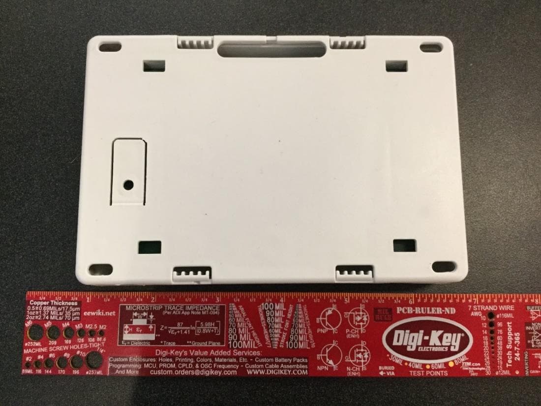
CCKPC0245
Apr 23, 20231101 Receiver
Equipment Class
DSS - Part 15 Spread Spectrum Transmitter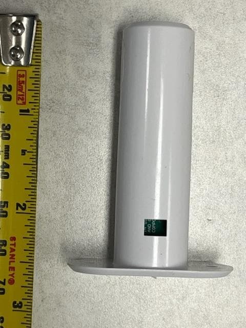
CCKPC0241
Dec 29, 20221132 Recessed contact
Equipment Class
DSS - Part 15 Spread Spectrum Transmitter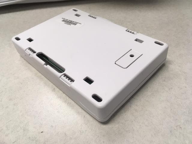
CCKPC0114R9
May 10, 2021Life Safety and security wireless receiver.
Equipment Class
DSS - Part 15 Spread Spectrum Transmitter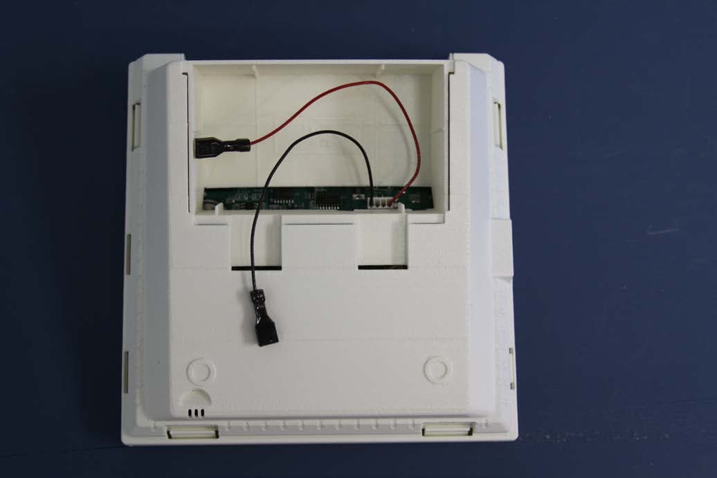
CCKPC0156
Oct 21, 2015Personal Emergency Response Base Unit
Equipment Class
DXX - Part 15 Low Power Communication Device Transmitter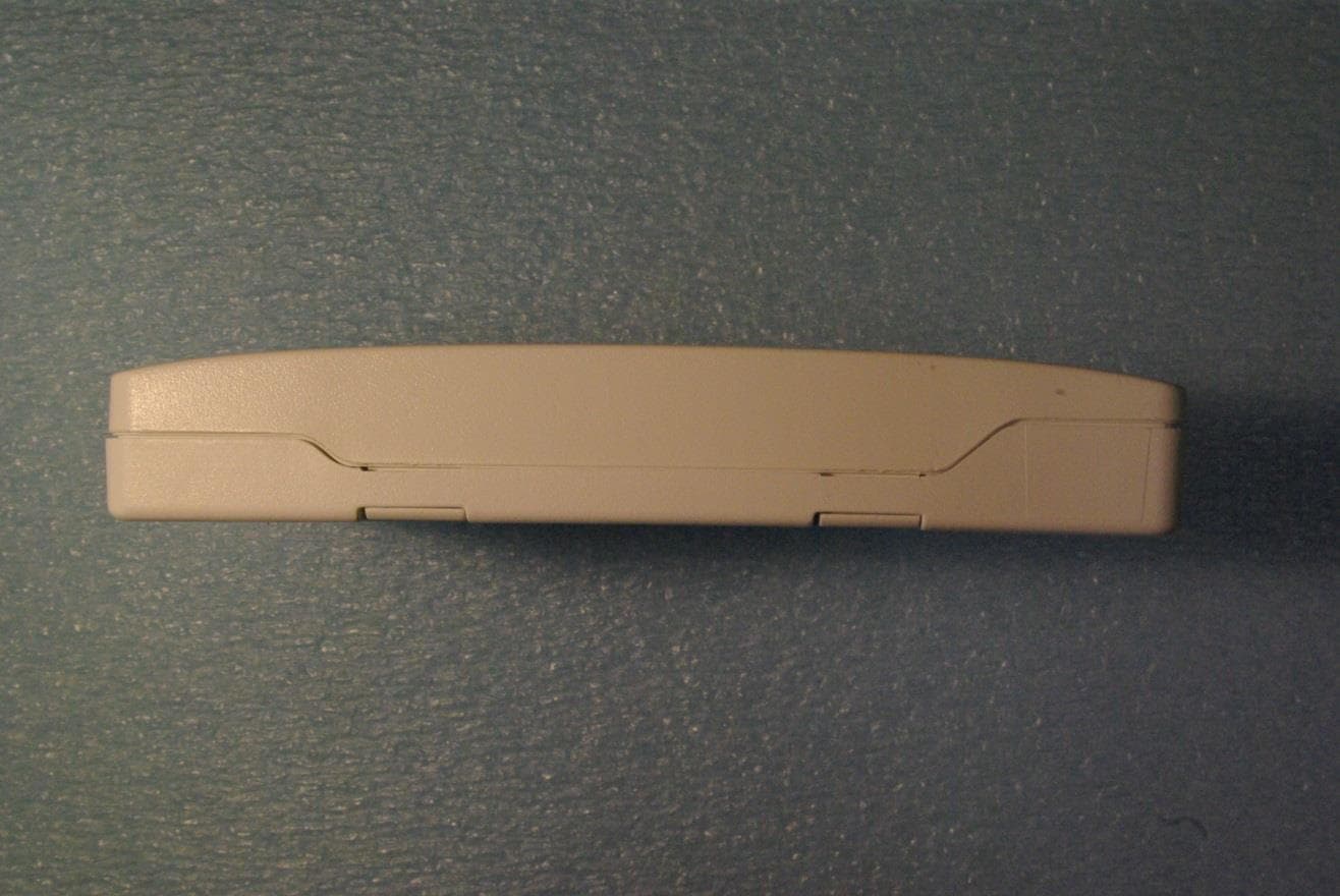
CCKPC0163
May 11, 2015Low Power Wireless Transceiver
Equipment Class
DXX - Part 15 Low Power Communication Device Transmitter