CCKPC0114R9Life Safety and security wireless receiver.
Digital Monitoring Products Inc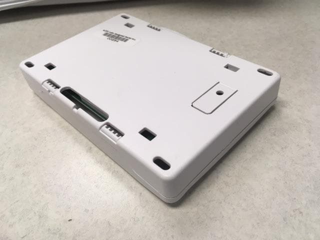
Click to zoom
Application Details
- Equipment Class
- DSS - Part 15 Spread Spectrum Transmitter
- Date of Grant
- May 10, 2021
- Application Purpose
- Original Equipment
- Date of Application
- May 10, 2021
- Equipment Note
- Life Safety and security wireless receiver.
- Frequency Range
- 905.60000000 - 924.40000000
- Country
- United States
Documents & Files
Document Text
Text extracted from the exhibit documents filed with the FCC. Open a document above to read the original.
Users Manual
1100DH SERIES HIGH POWER WIRELESS RECEIVERS Installation Guide Figure 1: 1100DH High Power Wireless Receiver RYGBTO PANEL The 1100DH Series Wireless Receiver provides up to 32 wireless zones for XT30/XT50 Series panels. The 1100DHE features 128-bit AES encryption. The 1100DH Series provides two-way, supervised communication using 900 MHz frequency hopping spread spectrum technology. The 1100DH contains additional transmit and receive amplifiers to enable greater distances for 1100 Series operation for harsh building environments. The additional gain introduced by this amplification may inhibit proper communication with 1100 Series transmitters located within 4 ft of the receiver. This distance may be 8 ft when using the 1122 PIR or 9000 Series Wireless Keypads. The system is designed so only one 1100DH is used per panel. Compatibility • XT30 Series panels • XT50 Series panels running firmware Version 102 or higher • Encryption requires panel Version 183 or higher • 1100T Translator requires receiver firmware Version 207/301 and higher What is Included? • One 1100DH Wireless Receiver • Hardware Pack 1 PROGRAM THE PANEL Refer to the panel programming guide as needed. 1. Reset the panel. 2. At a keypad, enter 6653 (PROG) to access the PROGRAMMER menu. 3. In SYSTEM OPTIONS, program a HOUSE CODE between 1 and 50. See House Code Explained for more information. 4. If you are programming an XT50 Series panel, select NO at the BUILT IN 1100 WIRELESS prompt to allow the panel to use the 1100DH for wireless communication. 5. (1100DHE only) At the 1100 ENCRYPTION prompt, select ALL to only add encrypted wireless devices to the system. Select BOTH to allow both encyrpted and non-encrypted wireless devices to be programmed. 6. (1100DHE only) The default passphrase appears at the ENTER PASSPHRASE prompt. Press CMD to keep the default. Press any select key or area to change the passphrase and enter an 8-character hexidecimal string (0-9, A-F). 7. Press CMD until STOP displays and press a select key or area to save and exit the Programmer. DESCRIPTION SELECT A LOCATION 2 The receiver should be centrally located between the DMP panel and the 1100 Series transmitters used in the installation based on the wiring specifications below. Use an 1106 Series Universal Wireless Transmitter to perform an LED survey. 1. With the cover removed, hold the transmitter in the desired location. 2. Press the tamper switch to send data to the panel and determine if communication is confirmed or faulty. Confirmed: If communication is confirmed, for each press or release of the tamper switch, the LED blinks immediately on and immediately off. Faulty: If communication is faulty, the LED remains on for about 8 seconds or flashes multiple times in quick succession. Relocate the receiver until the LED confirms clear communication. 2 1100DH SERIES INSTALLATION GUIDE | DIGITAL MONITORING PRODUCTS ADDITIONAL INFORMATION Black Green Yellow Red J4 RED PRO J8 XT30/XT50 Series Panel J7 RJ SUP AC 1 2 3 4567 8 10 1112 9 +B BELL GND SMK RED YEL GRN BLK AC -B 1100DH Receiver PANEL Can be extended from the panel up to 500 ft using 22 AWG or 1,000 ft using 18 AWG Figure 2: Wiring the 1100DH to the Panel Mounting Holes 3 The panel immediately recognizes the 1100DH if the panel is programmed with a house code. Do not use shielded wire between the panel and receiver. 1. Connect the red, yellow, green, and black wires to the PANEL terminal on the 1100DH. 2. Connect the other end of the wires to the terminals 7, 8, 9, and 10 on the panel. See Figure 2 3. Use the included #6 screws to secure the 1100DH to the surface. See Figure 2 for mounting hole locations. 4. Snap the cover back on to the base. WIRE AND MOUNT THE RECEIVER Table 1: Zone Number Designations DMP PANELAVAILABLE ZONESZONE RANGES XT50 with built-in receiver4811 - 14, 21 - 24, 31 - 34, 41 - 44, 51 - 54, 61 - 64, 71 - 74, 81 - 84, 80, 85 - 99 XT30 and XT50 (1100D Series)3211 - 14, 21 - 24, 31 - 34, 41 - 44, 51 - 54, 61 - 64, 71 - 74, 81 - 84 Wiring Specifications for Keypad Bus 1. DMP recommends using 18 or 22-gauge unshielded wire for all keypad and LX-Bus circuits. Do Not use twisted pair or shielded wire for LX-Bus and Keypad Bus data circuits. To maintain auxiliary power integrity when using 22-gauge wire do not exceed 500 feet. When using 18-gauge wire do not exceed 1,000 feet. Install an additional power supply to increase the wire length or add devices. 2. Maximum distance for any one circuit (length of wire) is 2,500 feet regardless of the wire gauge. This distance can be in the form of one long wire run or multiple branches with all wiring totaling no more than 2,500 feet. As wire distance from the panel increases, DC voltage on the wire decreases. 3. Maximum number of devices per 2,500 feet circuit is 40. 4. Maximum voltage drop between the panel (or auxiliary power supply) and any device is 2.0VDC. If the voltage at any device is less than the required level, add an auxiliary power supply at the end of the circuit. When voltage is too low, the devices cannot operate properly. Refer to the panel installation guide and LX-Bus/Keypad Bus Wiring Application Note (LT-2031). Programming Zones Refer to the panel XT30/XT50 Series Programming Guide (LT-0981) for complete wireless programming information. When any wireless input zone for a particular address is programmed, the 1100DH responds to the panel for this address. Other devices, such as keypads or hardwired zone expanders, cannot use this address. Zones connected directly to the panel cannot be wireless. See Table 1 for designated zone numbers. 1100DH SERIES INSTALLATION GUIDE | DIGITAL MONITORING PRODUCTS 3 Transmitter Supervision TIme For listed installations, program the transmitter supervision time in panel zone programming as listed in the following table. Refer to the panel programming guide for complete wireless programming information. LEDINDICATIONS RF RXFlashing yellow indicates data is being received from a transmit…
Text truncated - open the document above for the full version.
Users Manual
1100XH SERIES HIGH POWER WIRELESS RECEIVER Installation Guide 1 3 MOUNT THE 1100XH 1. Remove the cover from the plastic housing. 2. Use the included #6 screws to secure the 1100XH to the wall. See Figure 2 for mounting hole locations. 3. Use one of the provided screws to anchor the housing in the wall tamper screw hole. See Figure 2 for tamper location. PROGRAM THE PANEL RF RX RF TX PANEL RX PANEL TX WALL TAMPER ENABLE DISABLE STATUS PWR Figure 1: 1100XH High Power Wireless Receiver Refer to the panel programming guide as needed. 1. Reset the panel. 2. At a keypad, enter 6653 (PROG) to access the PROGRAMMER menu. 3. In SYSTEM OPTIONS, program a HOUSE CODE between 1 and 50. See House Code Explained for more information. 4. (1100XHE only) At the 1100 ENCRYPTION prompt, select ALL to only add encrypted wireless devices to the system. Select BOTH to allow both encrypted and non-encrypted wireless devices to be programmed. 5. (1100XHE only) The default passphrase appears at ENTER PASSPHRASE. Press CMD to keep the default. Press any select key or area to change the passphrase and enter an 8-character hexadecimal string (0-9, A-F). 6. Press CMD until STOP displays. Press a top row select key or area to save programming. DESCRIPTION The 1100XH Series High Power Wireless Receiver provides up to 100 wireless zones for XR150 Series panels and up to 500 wireless zones for XR550 Series panels. The 1100XHE features 128-bit AES encryption. The 1100XH provides two-way, supervised communication using 900 MHz frequency hopping- spread-spectrum technology. The 1100XH contains additional transmit and receive amplifiers to enable 1100 Series operation at greater distances or harsh building environments. The additional gain introduced by this amplification may inhibit proper communication with 1100 Series transmitters located within 4 ft of the receiver. This distance may be 8 ft when using the 1122 PIR or 9000 Series Wireless Keypads. The 1100XH is equipped with a case and wall tamper. Compatibility • XR150/XR550 Series Panels • Encryption requires panel Version 183 or higher • 1100T Translator requires receiver firmware Version 207/301 or higher What is Included? • 1100XH Series High Power Wireless Receiver • Model 300 Harness • Hardware Pack Tamper Puck Figure 2: Inside of the 1100XH Housing Mounting Hole 2 SELECT A LOCATION The receiver should be centrally located between the DMP panel and the 1100 Series transmitters used in the installation based on the wiring specifications below. Use an 1106 Series Universal Wireless Transmitter to perform an LED survey. 1. With the cover removed, hold the transmitter in the desired location. 2. Press the tamper switch to send data to the panel and determine if communication is confirmed or faulty. Confirmed: If communication is confirmed, for each press or release of the tamper switch, the LED blinks immediately on and immediately off. Faulty: If communication is faulty, the LED remains on for about 8 seconds or flashes multiple times in quick succession. Relocate the receiver until the LED confirms clear communication. 2 1100XH SERIES WIRELESS RECEIVER | DIGITAL MONITORING PRODUCTS Figure 3: Wiring The 1100XH to the Panel ADDITIONAL INFORMATION Wiring Specifications for X-Bus 1. DMP recommends using 18 or 22-gauge unshielded wire for all keypad and LX-Bus circuits. Do Not use twisted pair or shielded wire for LX-Bus and Keypad Bus data circuits. To maintain auxiliary power integrity when using 22-gauge wire do not exceed 500 feet. When using 18-gauge wire do not exceed 1,000 feet. Install an additional power supply to increase the wire length or add devices. 2. Maximum distance for any one circuit (length of wire) is 2,500 feet regardless of the wire gauge. This distance can be in the form of one long wire run or multiple branches with all wiring totaling no more than 2,500 feet. As wire distance from the panel increases, DC voltage on the wire decreases. 3. Maximum number of devices per 2,500 feet circuit is 40. 4. Maximum voltage drop between the panel (or auxiliary power supply) and any device is 2.0VDC. If the voltage at any device is less than the required level, add an auxiliary power supply at the end of the circuit. When voltage is too low, the devices cannot operate properly. Refer to the panel installation guide and LX-Bus/Keypad Bus Wiring Application Note (LT-2031). Programming Zones Refer to the panel XR150/XR550 Series Programming Guide (LT-1232) for complete wireless programming information. When any wireless input zone for a particular address is programmed, the 1100XH responds to the panel for this address. Other devices, such as keypads or hardwired zone expanders, cannot use this address. Zones connected directly to the panel cannot be wireless. See Table 1 for designated zone numbers. WIRE THE RECEIVER The panel immediately recognizes the 1100XH if the panel is programmed with a house code. Do not use shielded wire between the panel and receiver. 1. Connect the red, yellow, green, and black wires to the PANEL terminal on the 1100XH. 2. Connect the other end of the wires to the XBUS on the panel. See Figure 3. 3. Snap the cover back on to the base. Note: The receiver can’t operate if it’s connected to the keypad bus 4 Can be extended up to 500 ft from the panel using 22 AWG or 1,000 ft using 18 AWG XR150/XR550 Series Panel Battery Start Power LED 1100XH Receiver REC - Receive LED XMT - Transmit LED RF RX RF TX PANEL RX PANEL TX WALL TAMPER ENABLE DISABLE STATUS PWR PANEL TAMPER Table 1: Zone Number Designations DMP PANELAVAILABLE ZONESZONE RANGES XR150 (1100X Series)100500 - 599 XR550 (1100X Series)500500 - 999 1100XH SERIES WIRELESS RECEIVER | DIGITAL MONITORING PRODUCTS 3 Transmitter Supervision Time For listed installations, program the transmitter supervision time in panel zone programming as listed in the following table. Refer to the panel programming guide for complete wireless programming information. UL ListingListed AccessoriesSupervisio…
Text truncated - open the document above for the full version.
Cover Letter(s)
May 4, 2021 TIMCO Engineering 849 NW State Rd Newberry, FL 32669 To Whom It May Concern: This letter is to verify that the following personnel have permission to submit FCC and IC applications and to reply to correspondence on behalf of myself as representatives of Digital Monitoring Products, Inc. Amy Bade [email protected] James Wilson [email protected] ISED company number: 5251A FFC Grantee Code: CCK Best Regards, Brad Tucker VP - Product Management and Support Digital Monitoring Products, Inc.
Cover Letter(s)
April 23, 2021 Federal Communications Commission 445 12th St SW Washington DC 20554 Subject: Limited Agency Authorization Digital Monitoring Products, Inc. To Whom It May Concern: Digital Monitoring Products, Inc. (DMP), has authorized Timco Engineering (Timco) to act as our agent for the purpose of processing applications for equipment authorization with the FCC under all applicable parts of the FCC rules and regulations. This Limited Agency Authorization does not expire unless terminated by written notice to Timco and the Federal Communications Commission. Be advised that we are in full compliance with the Anti-Drug Abuse Act. The applicant is not subject to a denial of federal benefits pursuant to Section 5301 of the Anti-Drug Act of 1988, 21 U.S.C. 862, and no party to the application is subject to a denial of federal benefits pursuant to that section. We also declare that the information provided to the FCC is true and correct to the best of our knowledge (47 CFR 2.911(d)) and we have been informed of the grantee responsibilities (47 CFR 2.909) regarding certified equipment. If you have any questions or comments, please do not hesitate to contact me. Best regards, Brad Tucker VP - Product Management & Support Digital Monitoring Products, Inc.
Cover Letter(s)
April 23, 2021 Attention: Application Examiner RE: Request for Confidentiality Applicant: Digital Monitoring Products, Inc. FCC ID: CCKPC0114R9 To Whom It May Concern: This Permanent Confidentiality Request is hereby submitted by Digital Monitoring Products, Inc. to withhold permanently from public review certain portions of the application for equipment certification for the referenced FCC identifiers. This request for confidentiality is made pursuant to 47 CFR 0.457(d) and 0.459 of the FCC Rules. In particular, the following sections of the application are to be kept permanently confidential: • Schematics • Detailed Block Diagrams • Detailed Operational/Functional Description Digital Monitoring Products, Inc. has invested considerable time and materials in research and development to produce the referenced product. Disclosure of the permanently confidential portions of this application to competitors would not only give them significant competitive advantages in developing similar products, but would also disclose successful implementation of unpublished, leading edge technology developed by us. Sincerely, Brad Tucker VP - Product Management & Support
Cover Letter(s)
April 23, 2021 Federal Communications Commission Authorization and Evaluation Division 1435 Oakland Mills Rd Columbia MD 21046 To Whom It May Concern: Regarding CCKPC0114R9 label placement for this application, Digital Monitoring Products wishes to place the label inside the enclosure lid. This location will ensure the end user is able to view the label before operation. The identifier label will be readily viewable upon installation and each time the cover is opened. The equipment is required to be mounted before operation, thus exposing the label before operation. This location will help ensure the longevity of the label as this equipment may be in service in harsh environments. If you have any questions or comments, please do not hesitate to contact me. Best regards, Brad Tucker VP - Product Management & Support Digital Monitoring Products, Inc.
External Photos
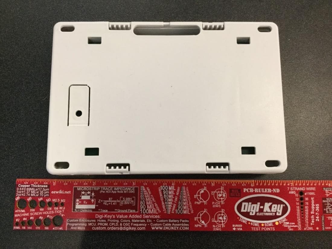
EXTERNAL PHOTOS EXTERNAL PHOTOS EXTERNAL PHOTOS EXTERNAL PHOTOS
ID Label/Location Info
Label location
Internal Photos
INTERNAL PHOTOS INTERNAL PHOTOS INTERNAL PHOTOS Antenna 905.6 - 924.4
RF Exposure Info
RF Exposure Page 1 of 1 FCC ID: CCKPC0114R9 IC: 5251A-PC0114R9 Using RSS-102, Issue 5 2.5.2 Exemption Limits for Routine Evaluation – RF Exposure Evaluation RF exposure evaluation is required if the separation distance between the user and/or bystander and the device’s radiating element is greater than 20 cm, except when the device operates as follows: •below 20 MHz6 and the source-based, time-averaged maximum e.i.r.p. of the device is equal to or less than 1 W (adjusted for tune-up tolerance); •at or above 20 MHz and below 48 MHz and the source-based, time-averaged maximum e.i.r.p. of the device is equal to or less than 4.49/ƒ0.5 W (adjusted for tune-up tolerance), where ƒ is in MHz; •at or above 48 MHz and below 300 MHz and the source-based, time-averaged maximum e.i.r.p. of the device is equal to or less than 0.6 W (adjusted for tune-up tolerance); •at or above 300 MHz and below 6 GHz and the source-based, time-averaged maximum e.i.r.p. of the device is equal to or less than 1.31 x 10⁻² ƒ^0.6834 W (adjusted for tune-up tolerance), where ƒ is in MHz; • at or above 6 GHz and the source-based, time-averaged maximum e.i.r.p. of the device is equal to or less than 5 W (adjusted for tune-up tolerance). In these cases, the information contained in the RF exposure technical brief may be limited to information that demonstrates how the e.i.r.p. was derived. EIRP compared to Limit Channel Frequency EIRP EIRP EIRP with +10% for tolerance Limit Result MHz dBm W W W 905.6 19.113 0.082 0.0902 1.371788 EXEMPT 915.0 21.102 0.129 0.1419 1.373551 EXEMPT 924.4 22.569 0.181 0.1991 1.395975 EXEMPT
Test Report
The Nebraska Center for Excellence in Electronics (NCEE) authorizes the above named company to reproduce this report provided it is reproduced in its entirety for use by the company’s employees only. Any use that a third party makes of this report, or any reliance on or decisions made based on it, are the responsibility of such third parties. NCEE accepts no responsibility for damages, if any, suffered by any third party as a result of decisions made or actions based on this report. This report applies only to the items tested. FCC/ISED Test Report Prepared for: Digital Monitoring Products Address: 2500 North Partnership Blvd. Springfield, MO 6582 Product: PC0114R9 FCC ID: CCKPC0114R9 IC: 5251A-PC0114R9 Test Report No: R20201019-20-E1C Approved by: __________________ Nic S. Johnson, NCE Technical Manager iNARTE Certified EMC Engineer #EMC-003337-NE DATE: 5 May 2021 Total Pages: 48 Report Number: R20201019-20-E1 Rev C Prepared for: Digital Monitoring Product The Nebraska Center for Excellence in Electronics 4740 Discovery Drive Lincoln, NE 68521 Page 2 of 48 REVISION PAGE Rev. No. Date Description 0 31 December 2020 Original – NJohnson Prepared by KVepuri A 5 February 2021 Corrected results in Section 4.0 and power limits. B 19 March 2021 Updated 3 rd table on Page 9. Updated duty cycle correction factor to match measurements in Section 4.6 C 5 May 2021 Added FCC Id and IC. Report Number: R20201019-20-E1 Rev B Prepared for: Digital Monitoring Product The Nebraska Center for Excellence in Electronics 4740 Discovery Drive Lincoln, NE 68521 Page 3 of 48 CONT EN TS Revision Page ............................................................................................................................................................................... 2 1.0 Summary of test results ....................................................................................................................................... 4 2.0 EUT Description .................................................................................................................................................... 5 2.1 Equipment under test ........................................................................................................................................ 5 2.2 Description of test modes ................................................................................................................................ 6 2.3 Description of support units ............................................................................................................................ 6 3.0 Laboratory description ......................................................................................................................................... 7 3.1 Laboratory description ...................................................................................................................................... 7 3.2 Test personnel ..................................................................................................................................................... 7 3.3 Test equipment.................................................................................................................................................... 8 4.0 Detailed results ...................................................................................................................................................... 9 4.1 Duty Cycle .......................................................................................................................................................... 10 4.2 Radiated emissions .......................................................................................................................................... 11 4.3 Peak Output Power .......................................................................................................................................... 19 4.4 Bandwidth ........................................................................................................................................................... 23 4.5 Bandedges ......................................................................................................................................................... 28 4.6 Carrier frequency seperation, number of hopping channels, time of occupancy ........................... 37 4.7 Conducted AC Mains Emissions .................................................................................................................. 42 Appendix A: Sample Calculation ................................................................................................................................... 45 Appendix B – Measurement Uncertainty ...................................................................................................................... 47 REPORT END ..................................................................................................................................................................... 48 Report Number: R20201019-20-E1 Rev B Prepared for: Digital Monitoring Product The Nebraska Center for Excellence in Electronics 4740 Discovery Drive Lincoln, NE 68521 Page 4 of 48 1.0 SU MMAR Y OF TEST R ESULT S The EUT has been tested according to the following specifications: (1) US Code of Federal Regulations, Title 47, Part 15 (2) ISED RSS-Gen, Issue 5 (3) ISED RSS-247, Issue 2 ANSI C63.10-2013 was used as a test method, with guidance from KBD 558074 D01 v05 SUMMARY Standard Section Test Type and Limit Result Remark FCC 15.203 Unique Antenna Requirement Pass PCB antenna FCC 15.35 RSS-Gen, 6.10 Duty cycle of pulsed emissions Informative only Duty cycle was applied FCC 15.209 RSS-Gen, 7.1 Receiver Radiated Emissions Pass Meets the requirement of the limit. FCC 15.247(a)(1)(i) RSS-247, 5.1(c) Minimum Bandwidth, Limit: Min. 250kHz Pass Meets the requirement of the limit. FCC 15.247(b)(1) RSS-247, 5.1 Maximum Peak Output Power, …
Text truncated - open the document above for the full version.
Test Setup Photos
Radiated emissions test setup Radiated emissions test setup Radiated emissions test setup Conducted emissions test setup Conducted emissions test setup Figure 1 - Radiated Emissions Test Setup, 1 - 25 GHz, (EUT not shown) Figure 2 - Radiated Emissions Test Setup, 30 MHz - 1 GHz, (EUT not shown) These photos are generic test photos showing the laboratory setup for the frequency ranges specified
Contact Information
Applicant
Brad Tucker(VP - Product Management and Support)
Test Firm
Nebraska Center for Excellence in ElectronicsNic Johnson
Technical Specifications
| # | Rule Parts | Frequency Range | Power Output |
|---|---|---|---|
| 1 | 15C | 905.6 MHz - 924.4 MHz | 722.60 mW |
Other Applications from Digital Monitoring Products Inc
CCKPC0245
Apr 23, 20231101 Receiver
Equipment Class
DSS - Part 15 Spread Spectrum Transmitter
CCKPC0241
Dec 29, 20221132 Recessed contact
Equipment Class
DSS - Part 15 Spread Spectrum Transmitter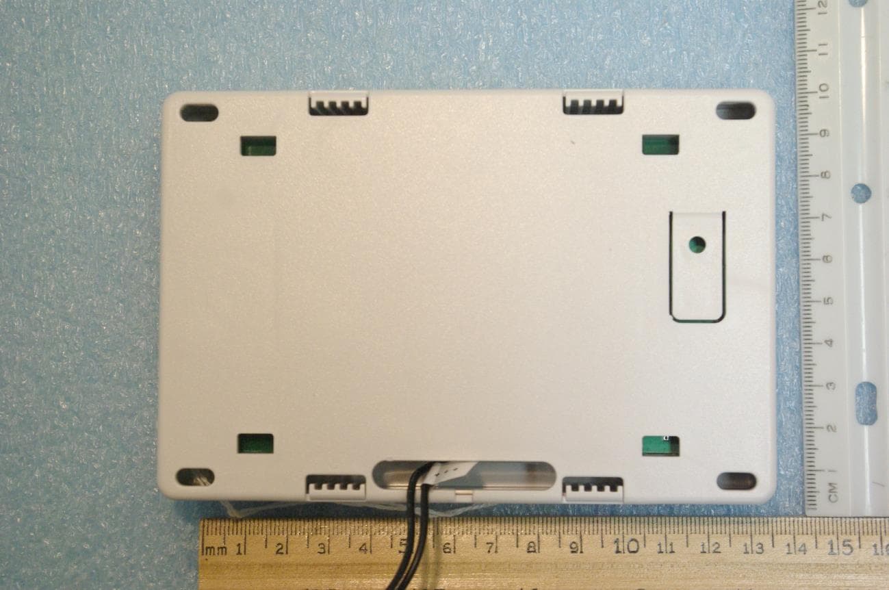
CCKPC0225
Jan 06, 2021900 MHz FHSS Transceiver System
Equipment Class
DSS - Part 15 Spread Spectrum Transmitter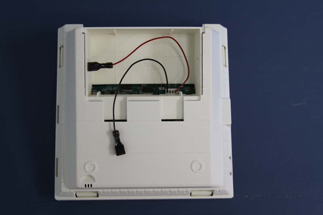
CCKPC0156
Oct 21, 2015Personal Emergency Response Base Unit
Equipment Class
DXX - Part 15 Low Power Communication Device Transmitter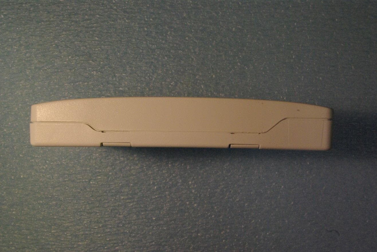
CCKPC0163
May 11, 2015Low Power Wireless Transceiver
Equipment Class
DXX - Part 15 Low Power Communication Device Transmitter