CCKPC02411132 Recessed contact
Digital Monitoring Products Inc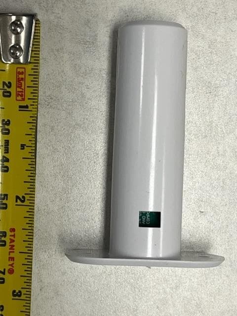
Click to zoom
Application Details
- Equipment Class
- DSS - Part 15 Spread Spectrum Transmitter
- Date of Grant
- Dec 29, 2022
- Application Purpose
- Original Equipment
- Date of Application
- Dec 28, 2022
- Equipment Note
- 1132 Recessed contact
- Frequency Range
- 903.30000000 - 926.60000000
- Country
- United States
Documents & Files
Document Text
Text extracted from the exhibit documents filed with the FCC. Open a document above to read the original.
Users Manual
INSTALLATION AND PROGRAMMING GUIDE 1132 Recessed Contact 1132 Installation and Programming Guide | Digital Monitoring Products 1 GET STARTED The 1132 is a wireless recessed contact that provides concealed protection for doors, windows, or any other application needing a discreet solution. As with all DMP 1100 Series transmitters, the onboard LED provides built‑in survey capability to allow for single‑person installations, eliminating the requirement for an external survey kit. The 1132 transmits Normal, Alarm, and Low Battery conditions. What’s Included ▶One 1132 Transmitter ▶One Magnet ▶One 3.6V Lithium 1/2 AA Battery What You’ll Need ▶3/4” Drill Bit ▶#1 Phillips screwdriver Procedure To install an 1132, this guide walks you through these required steps: 1. Program the panel. 2. Install the battery. 3. Select a location. 4. Mount the transmitter and magnet. 5. Test the transmitter. 1132 Installation and Programming Guide | Digital Monitoring Products 2 PROGRAM THE PANEL Refer to the panel programming guide as needed. After completing each of the following steps, press CMD to advance to the next prompt. 1. At a keypad, enter 6653 (PROG) to access the Programmer Menu. 2. At ZONE INFORMATION, enter the wireless zone number. 3. At *UNUSED*, enter the zone name. 4. At ZONE TYPE, press any select key or area and select the zone type. 5. At AREA NO, enter the area number. 6. At the NEXT ZN? prompt, select NO. 7. When WIRELESS? displays, select YES. 8. At SERIAL#, enter the eight‑digit device serial number. 9. At SUPRVSN TIME, enter a supervision time. Default is 240. 10. At the NEXT ZN? prompt, select YES if you are finished programming the zone. Select NO if you would like to access additional programming options. 11. To save panel programming, go to STOP and press CMD. 1132 Installation and Programming Guide | Digital Monitoring Products 3 INSTALL THE TRANSMITTER 1 Install the Battery Use only 3.6V 1/2 AA Lithium batteries. 1. Grasp the PCB and remove it from the housing. 2. Place the battery into the battery tray with the positive end of the battery facing the transmitter PCB. 3. Slide the battery tray and PCB into the housing. 4. Install the cap on the transmitter housing tube. Travel Distance Faulted—A fault will be detected when the door is at 2 1/2 inches. Restored—The fault will be restored when the door is at 1 1/2 inches. Figure 1: Assembling the Housing 2 Selection a Location The 1132 provides a Survey LED capability to allow one person to confirm communication with the wireless receiver or panel while the cover is removed. Move the magnet within 1/2 inch of the contact or pull it away from the contact to send data to the receiver. Confirmed: If communication is confirmed, the LED blinks once, immediately on and immediately off. Repeat this test to confirm five separate consecutive LED blinks. Any indication otherwise means proper communication has not been established. Repeat this test to confirm five separate consecutive LED blinks. Any indication otherwise means proper communication has not been established. Faulty: If communication is faulty, the LED remains on for about 8 seconds or flashes multiple times in quick succession. Relocate the contact or receiver until the LED confirms clear communication. For contact operation, the transmitter and magnet assembly should have no more than 1/2 inch between the housings after installation. When mounting on metal (ferrous) surfaces, this distance is slightly less. For door installations, it is recommended the transmitter be mounted in the door frame and the magnet assembly be mounted in the door. If the transmitter is installed in a metal door frame, the communication distance to the receiver may be reduced. Note: The LED will go to sleep to save battery life. If the LED does not turn on while performing an LED survey, reset the battery by removing the battery and re‑installing it in order to wake up the LED. 1132 Installation and Programming Guide | Digital Monitoring Products 4 Mount the Transmitter and Magnet 1. To install the transmitter, use a 3/4 inch drill bit and drill a hole at least 2 3/4 inch deep in the frame at the desired location. Caution: Avoid drilling in areas where electrical wiring runs through the wall. 2. Insert the transmitter housing into the hole until the flange is flush with the door jamb. 3. To install the magnet, use a 3/4 inch drill bit, drill a hole at least 3/4 inch deep in the door edge at the desired location. 4. Insert the magnet into the hole and press it into place. 3 Figure 2: Mounting the Transmitter and Magnet 0.75” DIA x 2.5” D 0.75” DIA x 0.63” D TEST THE TRANSMITTER After the transmitter has been installed, test to confirm that it is communicating reliably with the panel. Use the Tech APP™ to perform a Wireless Check‑in Test on the system or complete the following steps to perform a Wireless Check‑in Test from a keypad that is connected to the panel: At the keypad, enter 8144 (WALK) and select WLS. If the transmitter fails to check in at the keypad, check for sources of interference such as metal objects and electronic equipment. 1132 Installation and Programming Guide | Digital Monitoring Products 5 ADDITIONAL INFORMATION Supervision Time When a receiver is installed, powered up, or the panel is reset, the supervision time for transmitters is reset. If the receiver has been powered down for more than one hour, wireless transmitters may take up to an additional hour to send a supervision message unless tripped, tampered, or powered up. This operation extends battery life for transmitters. A missing message may display on the keypad until the transmitter sends a supervision message. Replace the Battery To replace the battery, complete the following steps. 1. To remove the transmitter cap, insert a small flathead screwdriver into the cap notch provided in the housing. Gently pry it upwards to remove the cap. 2. Slide the transmitter and battery assembly from the housing tube. Gently pull while g…
Text truncated - open the document above for the full version.
Cover Letter(s)
August 24, 2022 Federal Communications Commission 445 12th St SW Washington DC 20554 Subject: Limited Agency Authorization Digital Monitoring Products, Inc. FCC ID: CCKPC0241 To Whom It May Concern: Digital Monitoring Products, Inc. (DMP), hereby authorizes Nic Johnson of the Nebraska Center for Excellence in Electronics (NCEE) to act as our agent for the purpose of preparing and processing applications for equipment authorization with the FCC under all applicable parts of the FCC rules and regulations. This Limited Agency Authorization does not expire unless terminated by written notice to NCEE and the Federal Communications Commission. Be advised that we are in full compliance with the Anti-Drug Abuse Act. The applicant is not subject to a denial of federal benefits pursuant to Section 5301 of the Anti-Drug Act of 1988, 21 U.S.C. 862, and no party to the application is subject to a denial of federal benefits pursuant to that section. We also declare that the information provided to the FCC is true and correct to the best of our knowledge (47 CFR 2.911(d)) and we have been informed of the grantee responsibilities (47 CFR 2.909) regarding certified equipment. If you have any questions or comments, please do not hesitate to contact me. Best regards, Brad Tucker VP - Product Management & Support Digital Monitoring Products, Inc.
Cover Letter(s)
Page 1 of 1 Request for Confidentiality Date: December 28, 2022 Subject: Confidentiality Request for: FCC ID: CCKPC0241 Pursuant to FCC 47 CFR 0.457(d) the applicant requests that a part of the subject FCC application be held confidential. Type of Confidentiality Requested Exhibit ☐ Short Term ☒ Permanent ☐ Not Provided Block Diagrams ☐ Short Term ☐ Not Provided External Photos ☐ Short Term ☐ Permanent ☐ Not Provided Internal Photos ☐ Short Term ☒ Permanent ☐ Not Provided Operation Description/Theory of Operation ☐ Short Term ☐ Permanent ☒ Not Provided Parts List & Placement/BOM ☐ Short Term ☒ Permanent ☐ Not Provided Tune-Up Procedure ☐ Short Term ☒ Permanent ☐ Not Provided Schematics ☐ Short Term ☐ Not Provided Test Setup Photos ☐ Short Term ☐ Permanent ☐ Not Provided User’s Manual The above-mentioned company has spent substantial effort in developing this product and it is one of the first of its kind in industry. Having the subject information easily available to "competition" would negate the advantage they have achieved by developing this product. Not protecting the details of the design will result in financial hardship. Permanent Confidentiality: The applicant requests the exhibits listed above as permanently confidential be permanently withheld from public review due to materials that contain trade secrets and proprietary information not customarily released to the public. Short-Term Confidentiality (if applicable): Not applicable The applicant requests the exhibits selected above as short term confidential be withheld from public view for a period of 180 days from the date of the Grant of Equipment Authorization and prior to marketing. This is to avoid premature release of sensitive information prior to marketing or release of the product to the public. Applicant is also aware that they are responsible to notify ACB in the event information regarding the product or the product is made available to the public before the requested period has expired. ACB will then release the documents listed above for public disclosure pursuant to FCC Public Notice DA 04- 1705. NOTE for Industry Canada Applications: IC currently only distinguishes Permanent Confidentiality exhibits as shown above. Short Term confidentiality is not considered Provided to IC applications Sincerely, By: __________________________ Nic Johnson, Technical Manager, NCEE Labs
External Photos
EXTERNAL PHOTOS EXTERNAL PHOTOS EXTERNAL PHOTOS EXTERNAL PHOTOS
ID Label/Location Info
August 24, 2022 Federal Communications Commission Authorization and Evaluation Division 1435 Oakland Mills Rd Columbia MD 21046 To Whom It May Concern: Regarding CCKPC0241 label placement for this application, Digital Monitoring Products wishes to print the information directly onto the device circuit board. This location will ensure the end user is always able to view the information before operation. The identifier will be readily viewable upon installation and each time the cover is removed. If you have any questions or comments, please do not hesitate to contact me. Best regards, Brad Tucker VP - Product Management & Support Digital Monitoring Products, Inc.
ID Label/Location Info
LABEL
Internal Photos
INTERNAL PHOTOS INTERNAL PHOTOS INTERNAL PHOTOS
RF Exposure Info
Page 1 of 2 MPE Evaluation FCC ID: CCKPC0241 FCC Maximum exposure limits from CFR 47, FCC Part 1.1310: Table 1—Limits for Maximum Permissible Exposure (MPE) Frequency range (MHz) Electric field strength (V/m) Magnetic field strength (A/m) Power density (mW/cm 2 ) Averaging time (minutes) (A) Limits for Occupational/Controlled Exposure 0.3-3.0 614 1.63 *100 6 3.0-30 1842/f 4.89/f *900/f 2 6 30-300 61.4 0.163 1.0 6 300-1,500 f/300 6 1,500-100,000 5 6 (B) Limits for General Population/Uncontrolled Exposure 0.3-1.34 614 1.63 *100 30 1.34-30 824/f 2.19/f *180/f 2 30 30-300 27.5 0.073 0.2 30 300-1,500 f/1500 30 1,500-100,000 1.0 30 Page 2 of 2 Occupational/Controlled General Population/uncontrolled YES 1132 Frequency Power EIRP Power EIRP +10% for tolerance Power Density Limit at specified distance % of limit Result MHz mW mW mW/cm^2 mW/cm^2 903.3 14.03 15.43 0.003072 0.602200 0.51% PASS 915 18.84 20.72 0.004125 0.610000 0.68% PASS 926.6 16.71 18.38 0.003659 0.617733 0.59% PASS Distance 20 cm Note: The user’s manual will stipulate that a 20cm distance from the user is to be maintained. EIRP values in mW were multiplied by 1.1 to account for a 10% tolerance Antenna gain > 1, so EIRP was used since it would be higher than the conducted values The power density is calculated as shown below: S = (P x G)/(4 x π x d^2) – used to calculate exposure at 20 cm EIRP = P x G, measured as field strength d = √(S/(P x G) x 4 X π) – used to calculate minimum distance to meet limits S= power density P = transmitter conducted power (in mW) G = antenna numeric gain D = distance to radiation center (20 cm)
Test Report
Unit 1132, Antenna Gain Calculation DMP 1132 Peak Gain = 1.3 dBi Antenna gain is derived as follows. The Effective Isotropic Radiated Power (EIRP) is the product of the transmitter power and the transmitter antenna gain. The EIRP is reported in dBm. EIRP is measured at a distance of 3m from the EUT. The conducted power is measured directly at the output port from the transmitter module. The conducted power is a direct measurement of the transmitter power. The antenna gain is the difference, in dB, between the EIRP and the conducted power. Figures 1 through 3 show the corrected measurement of the EIRP. The correction adds 107dB to convert from dBm to field strength; adds the loss of the transducer; adds the loss of the cable. The intermediate result converts dBm to field strength at the receive antenna. Next, 95.23dB is subtracted to convert from field strength at the receive antenna to EIRP at the EUT transmitter. Table 1 lists the corrected EIRP values and frequencies. Figure 1. Corrected EIRP Measurement, Low Frequency Figure 2. Corrected EIRP Measurement, Mid Frequency Figure 3. Corrected EIRP Measurement, High Frequency Table 1: Corrected EIRP Frequency (MHz) Corrected EIRP (CEIRP dBm) 903.3 11.47 915.0 12.75 926.6 12.23 Figures 4 through 6 show the results of the conducted power measurements. Figure 4. Conducted power, Low Frequency Figure 5. Conducted power, Mid Frequency Figure 6. Conducted power, High Frequency Table 2 shows the calculated antenna gain and frequencies. Table 2. Antenna Gain Frequency (MHz) EIRP (dBm) Conducted Power (dBm) Peak Gain (dBi) 903.3 11.47 11.07 0.40 915.0 12.75 10.98 1.77 926.6 12.23 10.93 1.30
Test Report
The Nebraska Center for Excellence in Electronics (NCEE) authorizes the above named company to reproduce this report provided it is reproduced in its entirety for use by the company’s employees only. Any use that a third party makes of this report, or any reliance on or decisions made based on it, are the responsibility of such third parties. NCEE accepts no responsibility for damages, if any, suffered by any third party as a result of decisions made or actions based on this report. This report applies only to the items tested. FCC/ISED Test Report Prepared for: Digital Monitoring Products Address: 2500 North Partnership Blvd. Springfield, MO 6582 Product: 1132 Recessed contact Test Report No: R20220711-21-E1A Approved by: __________________ Nic S. Johnson, NCE Technical Manager iNARTE Certified EMC Engineer #EMC-003337-NE DATE: December 28, 2022 Total Pages: 37 Report Number: R20201019-20-E1 Rev A Prepared for: Digital Monitoring Product The Nebraska Center for Excellence in Electronics 4740 Discovery Drive Lincoln, NE 68521 Page 2 of 37 REVISION PAGE Rev. No. Date Description 0 18 August 2022 Original – NJohnson Prepared by GLarsen/FLane A 28 December 2022 Updated EUT name -NJ Report Number: R20220711-21-E1A Rev A Prepared for: Digital Monitoring Product The Nebraska Center for Excellence in Electronics 4740 Discovery Drive Lincoln, NE 68521 Page 3 of 37 CONT EN TS Revision Page ............................................................................................................................................................................... 2 1.0 Summary of test results ....................................................................................................................................... 4 2.0 EUT Description .................................................................................................................................................... 5 2.1 Equipment under test ........................................................................................................................................ 5 2.2 Description of test modes ................................................................................................................................ 6 2.3 Description of support units ............................................................................................................................ 6 3.0 Laboratory description ......................................................................................................................................... 7 3.1 Laboratory description ...................................................................................................................................... 7 3.2 Test personnel ..................................................................................................................................................... 7 3.3 Test equipment.................................................................................................................................................... 8 4.0 Detailed results ...................................................................................................................................................... 9 4.1 Duty Cycle .......................................................................................................................................................... 10 4.2 Radiated emissions .......................................................................................................................................... 11 4.3 Peak Output Power .......................................................................................................................................... 18 4.4 Bandwidth ........................................................................................................................................................... 21 4.5 Bandedges ......................................................................................................................................................... 24 4.6 Carrier Frequency Seperation, Number of Hopping Channels, Time of occupancy ....................... 29 Appendix A: Sample Calculation ................................................................................................................................... 34 Appendix B – Measurement Uncertainty ...................................................................................................................... 36 REPORT END ..................................................................................................................................................................... 37 Report Number: R20220711-21-E1A Rev A Prepared for: Digital Monitoring Product The Nebraska Center for Excellence in Electronics 4740 Discovery Drive Lincoln, NE 68521 Page 4 of 37 1.0 SU MMAR Y OF TEST R ESULT S The EUT has been tested according to the following specifications: (1) US Code of Federal Regulations, Title 47, Part 15 (2) ISED RSS-Gen, Issue 5 (3) ISED RSS-247, Issue 2 ANSI C63.10-2013 was used as a test method, with guidance from KBD 558074 D01 v05 SUMMARY Standard Section Test Type and Limit Result Remark FCC 15.203 Unique Antenna Requirement Pass PCB antenna FCC 15.35 RSS-Gen, 6.10 Duty cycle of pulsed emissions Informative only Duty cycle was applied FCC 15.209 RSS-Gen, 7.1 Receiver Radiated Emissions Pass Meets the requirement of the limit. FCC 15.247(a)(1)(i) RSS-247, 5.1(c) Maximum Bandwidth, Limit: Max. 250kHz Pass Meets the requirement of the limit. FCC 15.247(b)(1) RSS-247, 5.1 Maximum Peak Output Power, Limit: Max. 24 dBm Pass Meets the requirement of the limit. FCC 15.209 RSS-Gen, 8.9 RSS-247, 5.5 Transmitter Radiated Emissions Pass Meets the requirement of the limit. FCC 15.247(a) (1) (i) RSS-247, 5.1(c) Frequency hopping system, Limit: Max. 0.4 Seconds in 20 Second Period Pass Meets the requirement of the limit. FCC 15.209, 15.205 RSS-Gen, 8.9 R…
Text truncated - open the document above for the full version.
Test Setup Photos
TEST SETUP PHOTOS TEST SETUP PHOTOS TEST SETUP PHOTOS x-axis TEST SETUP PHOTOS y-axis TEST SETUP PHOTOS z-axis TEST SETUP PHOTOS
Contact Information
Applicant
Brad Tucker(VP - Product Management and Support)
Test Firm
Nebraska Center for Excellence in ElectronicsKarthik Vepuri
Technical Specifications
| # | Rule Parts | Frequency Range | Power Output |
|---|---|---|---|
| 1 | 15C | 903.3 MHz - 926.6 MHz | 14.00 mW |
Other Applications from Digital Monitoring Products Inc
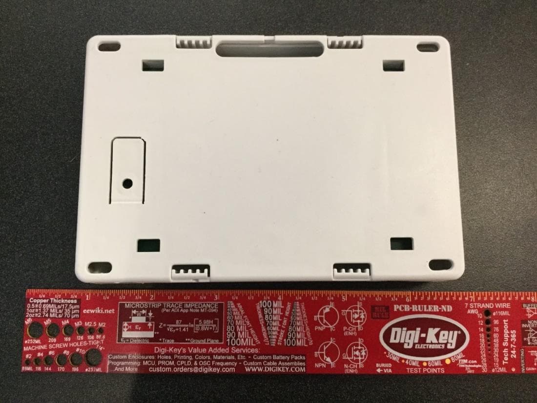
CCKPC0245
Apr 23, 20231101 Receiver
Equipment Class
DSS - Part 15 Spread Spectrum Transmitter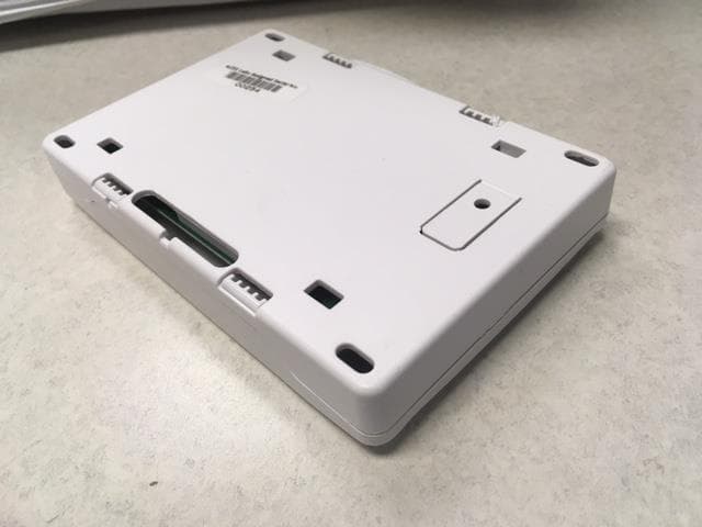
CCKPC0114R9
May 10, 2021Life Safety and security wireless receiver.
Equipment Class
DSS - Part 15 Spread Spectrum Transmitter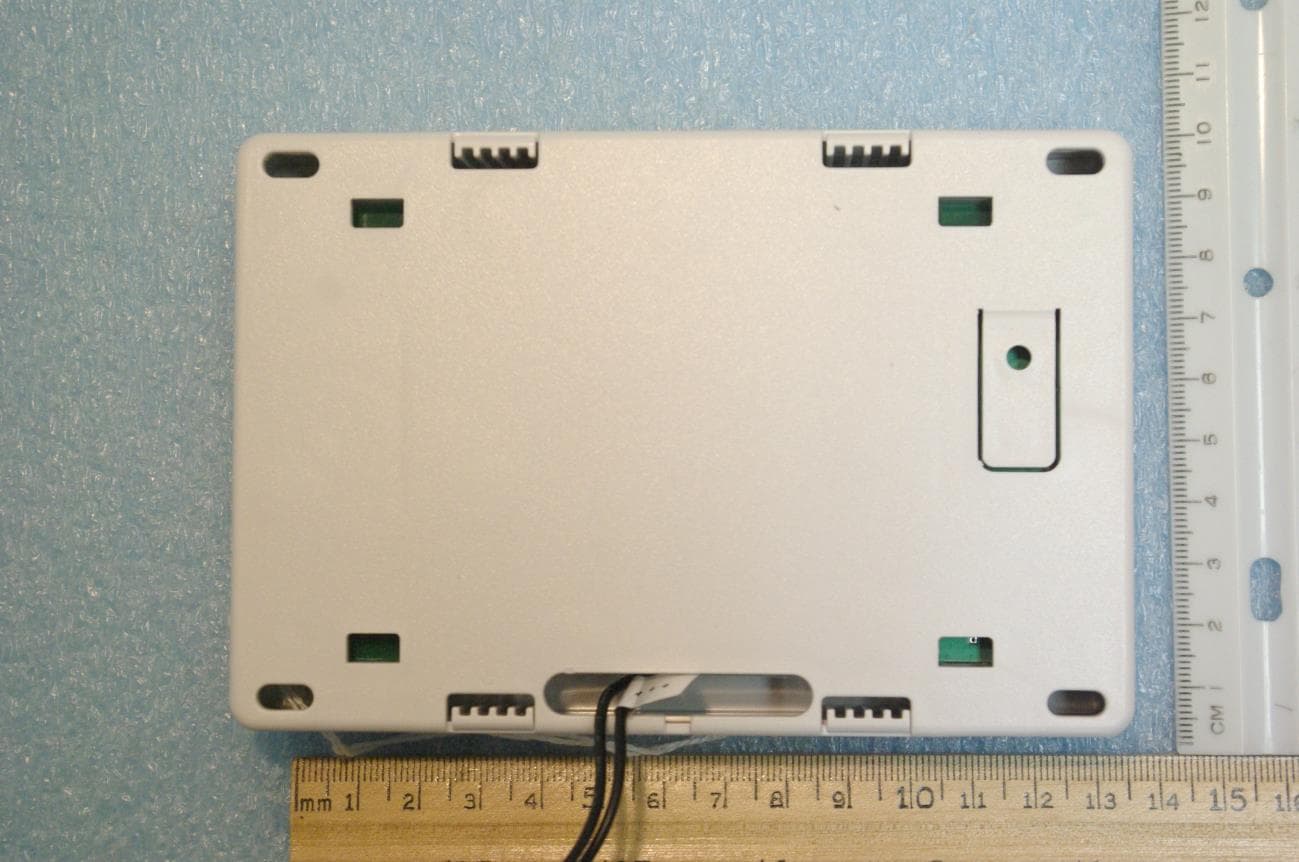
CCKPC0225
Jan 06, 2021900 MHz FHSS Transceiver System
Equipment Class
DSS - Part 15 Spread Spectrum Transmitter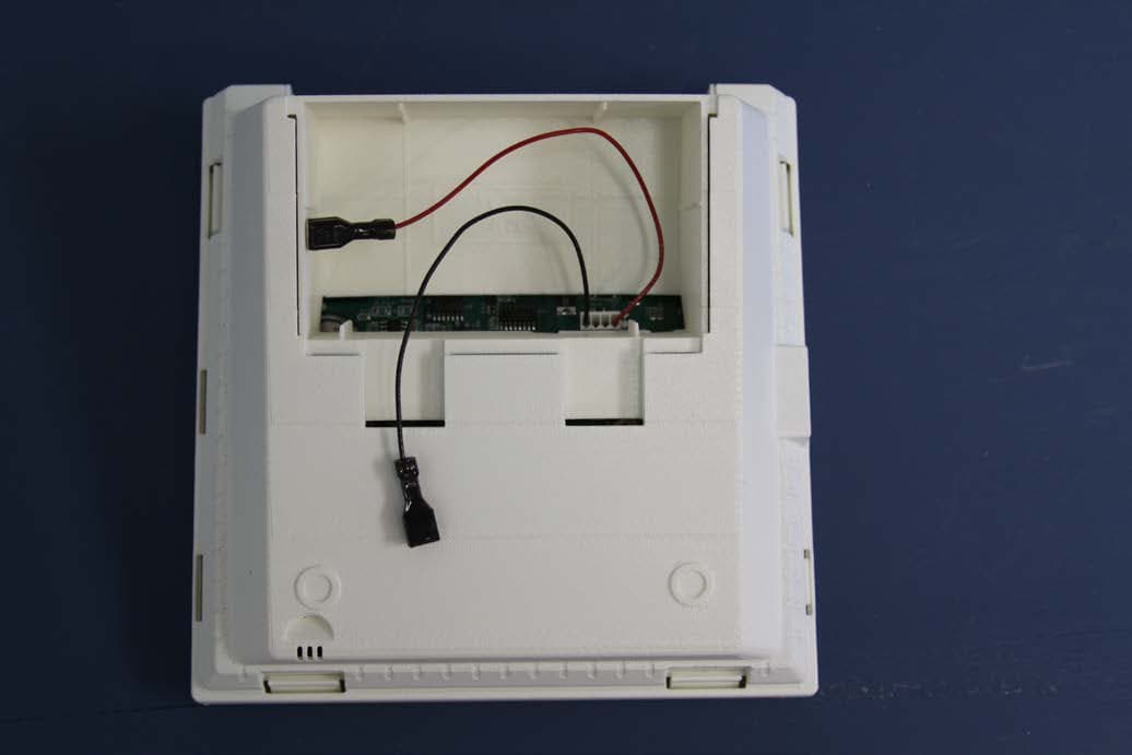
CCKPC0156
Oct 21, 2015Personal Emergency Response Base Unit
Equipment Class
DXX - Part 15 Low Power Communication Device Transmitter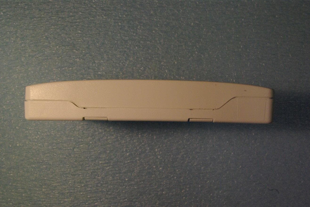
CCKPC0163
May 11, 2015Low Power Wireless Transceiver
Equipment Class
DXX - Part 15 Low Power Communication Device Transmitter