CCKPC0156Personal Emergency Response Base Unit
Digital Monitoring Products Inc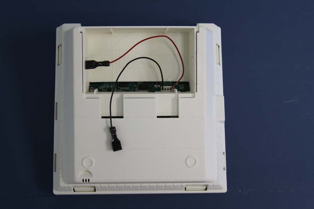
Click to zoom
Application Details
- Equipment Class
- DXX - Part 15 Low Power Communication Device Transmitter
- Date of Grant
- Oct 21, 2015
- Application Purpose
- Original Equipment
- Date of Application
- Oct 21, 2015
- Equipment Note
- Personal Emergency Response Base Unit
- Frequency Range
- 905.00000000 - 925.00000000
- Country
- United States
Documents & Files
Document Text
Text extracted from the exhibit documents filed with the FCC. Open a document above to read the original.
Users Manual
LT-1329 © 2014 LifeStation 14475 LifeStation ® Call us toll free at 877.833.2020 LifeStationCall us toll free at 877.833.2020 LifeStation CANCEL TROUBLE COMM STATUS TEST POWER Bracelet Clip Bracelet Clip Lanyard Clip Lanyard Clip TELEPHONE Wall Jack ELECTRICAL Wall Jack 16.5 V AC HOUSE PHONE VOLUME PHONE LINE EM20D Console Home Phone 16.5Vac Power Adapter “Now we will test the range of your emergency pendants in various rooms. Press the help button when you are ready to start the range test.” Step 5. Setting up your Help Button “Press each emergency pendant in each room. Press the help button to complete the test.” When a pendant or help button is detected: “Pendant detected.” “Thank you, we have now finished setting up your communicator. Congratulations! Please press your help button to send your first call to the personal response associate.” Press the help button Step 6. Placing a Test Call Press and release the Test Button within 3 seconds to place a test call. “Test call is now being placed. Please stand by.” If you do not get a response, review Step 3. Step 4. Connecting your Home Phone Connect your home phone cord to the gray connection on the back of the Console. Choose either the wrist strap or break-away lanyard option for the 1148 Emergency Pendant. Step 1. Selecting your Help Button Option Quick Start Guide SELECTING YOUR HELP BUTTON OPTION CONNECTING THE POWER SUPPLY CONNECTING THE PHONE LINE CONNECTING YOUR HOME PHONE SETTING UP YOUR HELP BUTTON PLACING A TEST CALL What is Included • One EM20 Console • One 12V DC Battery - installed • Color-coded phone cord • 16.5VAC Power Adapter • 1148 Emergency Pendant Wrist strap Break-away Lanyard CANCEL TROUBLE COMM STATUS TEST POWER CANCEL TROUBLE COMM STATUS TEST POWER CANCEL TROUBLE COMM STATUS TEST POWER PRELIMINARY PRELIMINARY Call us toll free at 877.833.2020 if you need any assistance in setting up your system. LifeStation Step 2. Connecting the Power Supply CANCEL TROUBLE COMM STATUS TEST POWER 13.6 V AC VOLUME PHONE LINE HOUSE PHONE 13.6 V AC VOLUME PHONE LINE HOUSE PHONE 1. Unpack the power supply and fully unroll the cord. 2. Connect the power supply to the red connection on the back of the Console. 3. Connect the power supply to an electrical outlet and secure with the provided screw through tab on the power supply. CANCEL TROUBLE COMM STATUS TEST POWER “Welcome! We will now help you setup your communicator step-by-step. If you miss a step, wait, and we will repeat the instructions.” Step 3. Connecting the Phone Line 1. Unpack the color-coded phone cord and fully unroll. If no phone line is detected within one minute: “Good, your communicator is now plugged in. You may press the help button to continue.” “Your communicator has not been correctly plugged in to the phone line. See step 3 in the quick start guide.” The Voice Prompt Setup begins automatically when power is applied. The setup cannot be exited until completed. If power is somehow interrupted and the setup does not complete, it will start over when power is restored. During the Voice-Prompt Setup the last message will repeat once for each minute of inactivity. “Please find the quick start guide located in the box. When you have the guide in front of you, press the help button.” 2. Connect the color-coded phone cord to the green connection on the back of the Console. Next, we will plug the gray phone cord into a phone jack in the wall. You may need to unplug your phone temporarily, and reconnect it in the next step.” CANCEL TROUBLE COMM STATUS TEST POWER CANCEL TROUBLE COMM STATUS TEST POWER Next, we will plug your phone into the back of the communicator if necessary. Refer to step 4 in the quick start guide. Please press the help button to continue.” When a phone line is detected: When power is applied, the Voice Prompt Setup begins. 3. Connect the opposite end to the phone wall jack. PRELIMINARY PRELIMINARY
Users Manual
InstallatIon GuIde EM20 PERSONAL EMERGENCY RESPONSE SYStEM CONSOLE CANCEL TEST TROUBLE COMM POWER TROUBLE COMM POWER MODEL EM20 INSTALLATION GUIDE FCC NOTICE This equipment has been tested and found to comply with the limits for a Class B digital device, pursuant to part 15 of the FCC Rules. These limits are designed to provide reasonable protection against harmful interference in a residential installation. This equipment generates, uses and can radiate radio frequency energy and, if not installed and used in accordance with the instructions, may cause harmful interference to radio communications. However, there is no guarantee that interference will not occur in a particular installation. If this equipment does cause harmful interference to radio or television reception, which can be determined by turning the equipment off and on, the user is encouraged to try to correct the interference by one or more of the following measures: • Reorient or relocate the receiving antenna. • Increase the separation between the equipment and receiver. • Connect the equipment into an outlet on a circuit different from that to which the receiver is connected. • Consult the dealer or an experienced radio/TV technician for help. Changes or modifications not expressly approved by the party responsible for compliance could void the user’s authority to operate the equipment. This device has been designed to operate with the integrated 1100 Series PCB antenna having a maximum gain of 1.8 dB. Antennas having a gain greater than 1.8 dB are strictly prohibited for use with this device. The required antenna impedance is 50 ohms. If necessary, the installer should consult the dealer or an experienced radio/television technician for additional suggestions. The installer may find the following booklet, prepared by the Federal Communications Commission, helpful: “How to identify and Resolve Radio-TV Interference Problems.” This booklet is available from the U.S. Government Printing Office, Washington D.C. 20402 Stock No. 004-000-00345-4 Industry Canada Information This device complies with Industry Canada Licence-exempt RSS standard(s). Operation is subject to the following two conditions: (1) this device may not cause interference, and (2) this device must accept any interference, including interference that may cause undesired operation of the device. Le présent appareil est conforme aux CNR d’Industrie Canada applicables aux appareils radio exempts de licence. L’exploitation est autorisée aux deux conditions suivantes : (1) l’appareil ne doit pas produire de brouillage, et (2) l’utilisateur de l’appareil doit accepter tout brouillage radioélectrique subi, même si le brouillage est susceptible d’en compromettre le fonctionnement. © 2015 Digital Monitoring Products, Inc. Information furnished by DMP is believed to be accurate and reliable. This information is subject to change without notice. Caution Notes Throughout this guide you will see caution notes containing information you need to know when installing the EM20. These cautions are indicated with a yield sign. Whenever you see a caution note, make sure you completely read and understand its information. Failing to follow the caution note can cause damage to the equipment or improper operation of one or more components in the system. Table of ConTenTs Digital Monitoring Products iii Specifications 1.1 Power Supply .....................................................................................................1 1.2 Communication ...................................................................................................1 1.3 Enclosure Specifications ......................................................................................1 Introduction 2.1 System Configurations .........................................................................................1 System Components 3.1 Wiring Diagram ...................................................................................................1 3.2 Accessory Devices ...............................................................................................1 Installation 4.1 Location Information ...........................................................................................2 Primary Power Supply 5.1 AC Power Supply ................................................................................................2 Secondary Power Supply 6.1 Standby Battery ..................................................................................................2 6.2 Battery Supervision .............................................................................................2 Status Light Operation 7.1 Status Lights ......................................................................................................3 Programming Connection 8.1 Programming Connection ....................................................................................3 8.2 Low Power Shutdown ..........................................................................................3 On-Board 1100 Series Wireless 9.1 Wireless Antenna ................................................................................................3 Telephone Connections 10.1 Telephone ..........................................................................................................4 10.2 Cellular ..............................................................................................................4 10.3 FCC Registration .................................................................................................4 10.4 Notification .........................................................................................................4 10.5 CS-03 Registration Information ............................................................................4 EM20 Personal Emergency Response System Console Compliance Home Health Care Signaling Equipment ....................................................................…
Text truncated - open the document above for the full version.
Cover Letter(s)
Federal Communications Commission Authorization and Evaluation Division Confidentiality Request regarding application for certification of FCC ID: CCKPC0156. Pursuant to Sections 0.457 and 0.459 of the Commission’s Rules, we hereby request confidential treatment of information accompanying this application as outlined below: Exhibit Type File Name Block Diagram Schematics Operational Description Block Diagrams.pdf EM 20-PC-0156-R5-XF Schem.pdf Theory Of Operation-EM20.doc The above materials contain trade secrets and proprietary information not customarily released to the public. The public disclosure of these materials may be harmful to the applicant and provide unjustified benefits to its competitors. The applicant understands that pursuant to Section 0.457 of the Rules, disclosure of this application and all accompanying documentation will not be made before the date of the Grant for this application. Sincerely, Terry Shelton Director of Technical Design
External Photos
EXTERNAL PHOTOS Front Top BACK Bottom Left Side Right Side
ID Label/Location Info
July 31, 2015 Regarding FCC ID label placement for the Model EM20, FCC ID: CCKPC0156 and IC: 5251A-PC0156 applications, DMP wishes to print the information directly onto the device printed circuit board. This location will ensure the end user is always able to view the information before operation. The identifier will be readily viewable upon installation and each time the cover is removed. The equipment is sold and required to be mounted before operation thus exposing the information before operation. This location will help ensure the longevity of the information as this equipment may be in service in harsh environments. Best Regards, Terry Shelton | Director of Technical Design Digital Monitoring Products | dmp.com 417.831.9362 | Fax 417.447.9698 Lb
Internal Photos
APPLICANT: DIGITAL MONITORING PRODUCTS FCC ID: CCKPC0156 IC: 5251A-PC0156 INTERNAL PHOTOS
Test Report
FCC PART 15.249 & IC RSS-210 UNLICENSED INTENTIONAL RADIATOR TEST REPORT Applicant DIGITAL MONITORING PRODUCTS Address 2500 N. PARTNERSHIP BLVD. SPRINGFIELD MISSOURI 65802 USA FCC ID CCKPC0156 IC Certification Number 5251A-PC0156 Model Number EM20 Product Description PERSONAL EMERGENCY RESPONSE BASE UNIT Date Sample Received 9/10/2015 Final Test Date 9/15/2015 Tested By Tim Royer Approved By Cory Leverett Report Number Version Number Description Issue Date 1504AUT15TestReport Rev1 Initial Issue 9/30/2015 THE ATTACHED REPORT SHALL NOT BE REPRODUCED EXCEPT IN FULL WITHOUT THE WRITTEN APPROVAL OF TIMCO ENGINEERING, INC. 849 NW State Road 45 Newberry, FL 32669 USA Ph.: 888.472.2424 or 352.472.5500 Fax: 352.472.2030 Email: [email protected] Website: www.timcoengr.com Table of Contents GENERAL REMARKS ........................................................................................... 3 GENERAL INFORMATION .................................................................................... 4 TEST RESULTS SUMMARY ................................................................................... 5 RADIATION INTERFERENCE ................................................................................ 6 OCCUPIED BANDWIDTH ..................................................................................... 9 BAND-EDGE .................................................................................................... 15 AC POWER LINE CONDUCTED INTERFERENCE ..................................................... 19 EMC EQUIPMENT LIST ...................................................................................... 22 APPLICANT: DIGITAL MONITORING PRODUCTS FCC ID: CCKPC0156 IC: 5251A-PC0156 REPORT: 1504AUT15TestReport.docx Page 3 of 22 GENERAL REMARKS The attached report shall not be reproduced except in full without the written permission of Timco Engineering Inc. Summary The device under test does: Fulfill the general approval requirements as identified in this test report Not fulfill the general approval requirements as identified in this test report Attestations This equipment has been tested in accordance with the standards identified in this test report. To the best of my knowledge and belief, these tests were performed using the measurement procedures described in this report. All instrumentation and accessories used to test products for compliance to the indicated standards are calibrated regularly in accordance with ISO 17025: 2005 requirements. I attest that the necessary measurements were made, under my supervision, at: Timco Engineering Inc. 849 NW State Road 45 Newberry, FL 32669 Authorized Signatory Name: Tim Royer Project Manager Date: 9/30/2015 Table of Contents APPLICANT: DIGITAL MONITORING PRODUCTS FCC ID: CCKPC0156 IC: 5251A-PC0156 REPORT: 1504AUT15TestReport.docx Page 4 of 22 GENERAL INFORMATION EUT Specification FCC Regulatory Standard Title 47 CFR Part 2 & 15 IC Regulatory Standard RSS-210 (i8) & RSS-GEN (i4) FCC ID CCKPC0156 IC Certification 5251A-PC0156 Model EM20 EUT Description PERSONAL EMERGENCY RESPONSE BASE UNIT Operating Frequency TX: 902-928MHz RX: 902-928MHz EUT Power Source 110–120Vac/50– 60Hz DC Power Battery Operated Exclusively Test Item Prototype Pre- Production Production Type of Equipment Fixed Mobile Portable Antenna Connector Integrated Antenna Antenna N/A Test Facility Timco Engineering Inc. located at 849 NW State Road 45 Newberry, FL 32669 USA. Test Conditions Temperature: 24-26ºC Relative humidity: 50-65% Measurement Standards ANSI C63.10-2013 (test methods) ANSI C63.4-2009 (Site Validation) Test Exercise EUT was connected to 110vAC through supplied power supply. The telephone connector was terminated with a standard telephone. The telephone wall connector was connected to a loop simulator to simulate normal operation. APPLICANT: DIGITAL MONITORING PRODUCTS FCC ID: CCKPC0156 IC: 5251A-PC0156 REPORT: 1504AUT15TestReport.docx Page 5 of 22 Test Supporting Equipment Device Manufacturer Model S/N Supplied By Use Loop Simulator Timco N/A N/A Timco Simulator Telephone AT&T N/A N/A Timco Load TEST RESULTS SUMMARY Requirement FCC Rule Part IC RSS Result Fundamental & Harmonic Emissions 15.249 (a)(c)(e) 210 § A2.9 Pass Occupied Bandwidth 15.215 (c) GEN § 6.6 Pass Bandedge Compliance 15.249 (c)(d)(e) 15.209 210 § A2.9(b) GEN § 8.9 Pass Spurious Emissions 15.249 (c)(d)(e) 15.209 210 § A2.9(b) GEN § 8.9 Pass AC Power Line Conducted Emissions 15.207 GEN § 8.8 Pass Restricted Band Emissions 15.205 210 § 2.2 GEN § 8.10 Pass Antenna Requirements 15.203 GEN § 8.3 Pass Notes: Table of Contents APPLICANT: DIGITAL MONITORING PRODUCTS FCC ID: CCKPC0156 IC: 5251A-PC0156 REPORT: 1504AUT15TestReport.docx Page 6 of 22 RADIATION INTERFERENCE Rules Part No.: FCC 15.249, 15.209 & IC RSS-210 ANNEX A2.9 (b), GEN § 8.9 Requirements: Frequency Limits Part 15.209 & RSS-GEN 8.9 9 to 490 kHz 2400/F (kHz) μV/m @ 300 meters 490 to 1705 kHz 24000/F (kHz) μV/m @ 30 meters 1705 kHz to 30 MHz 29.54 dBμV/m @ 30 meters 30 – 88 40.0 dBμV/m @ 3 meters 80 – 216 43.5 dBμV/m @ 3 meters 216 – 960 46.0 dBμV/m @ 3 meters Above 960 54.0 dBμV/m @ 3 meters Part 15.249 & RSS-210 (i8) ANNEX A.2.9 Fundamental 902 – 928 MHz 94.0 dBμV/m @ 3 meters Fundamental 2.4 – 2.4835 GHz 94.0 dBμV/m @ 3 meters Harmonics 54.0 dBμV/m @ 3 meters Method of Measurement: ANSI C63.10 using a spectrum analyzer, a preselector, a quasi- peak adapter, and an appropriate antenna. The analyzer was calibrated in dB above a microvolt at the output of the antenna. The resolution bandwidth was 100 kHz with an appropriate sweep speed and the video bandwidth was 300 kHz up to 1 GHz and 1 MHz with a video BW of 3 MHz above 1 GHz. When an emission was found, the table was rotated to produce the maximum signal strength. The antenna was placed in both the horizontal and vertical planes and the worst case emissions were reported. The spectrum was searched to at least the tenth (10) harmonic of the fundamental. Emissions were scanned from…
Text truncated - open the document above for the full version.
Test Setup Photos
APPLICANT: DIGITAL MONITORING PRODUCTS FCC ID: CCKPC0156 IC: 5251A-PC0156 TEST SET UP PHOTOS RADIATION INTERFERENCE 20 dB % 99% BANDWIDTH BANDEDGE POWERLINE CONDUCTED EMISSIONS
Contact Information
Applicant
Brad Tucker(VP - Product Management and Support)
Technical Contact
Non-Technical Contact
Timco Engineering, Inc.Sharon Hoffman
[email protected]888-427-2424
Test Firm
Timco Engineering, Inc.Bruno Clavier
Technical Specifications
| # | Rule Parts | Frequency Range | Power Output |
|---|---|---|---|
| 1 | 15C | 905 MHz - 925 MHz | - |
Other Applications from Digital Monitoring Products Inc
CCKPC0245
Apr 23, 20231101 Receiver
Equipment Class
DSS - Part 15 Spread Spectrum Transmitter
CCKPC0241
Dec 29, 20221132 Recessed contact
Equipment Class
DSS - Part 15 Spread Spectrum Transmitter
CCKPC0114R9
May 10, 2021Life Safety and security wireless receiver.
Equipment Class
DSS - Part 15 Spread Spectrum Transmitter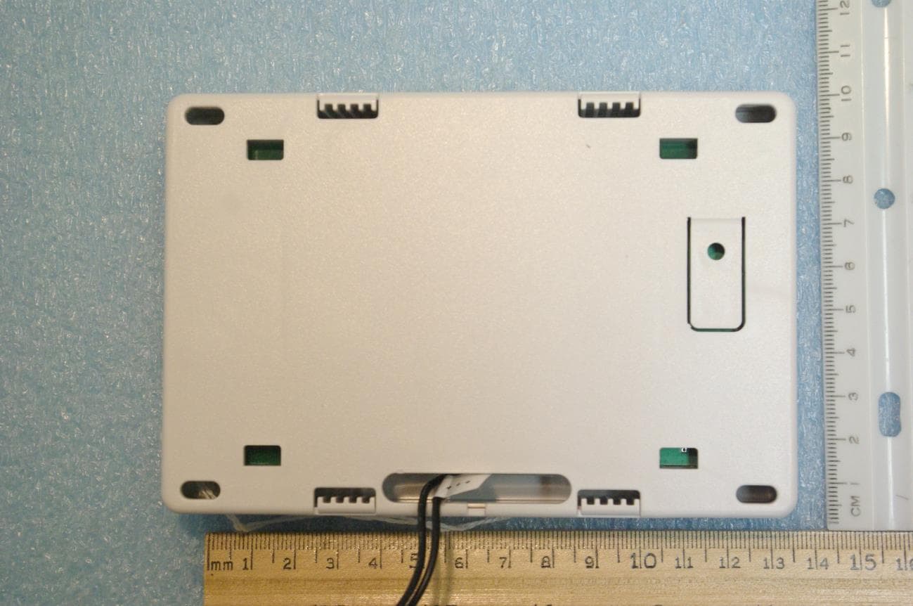
CCKPC0225
Jan 06, 2021900 MHz FHSS Transceiver System
Equipment Class
DSS - Part 15 Spread Spectrum Transmitter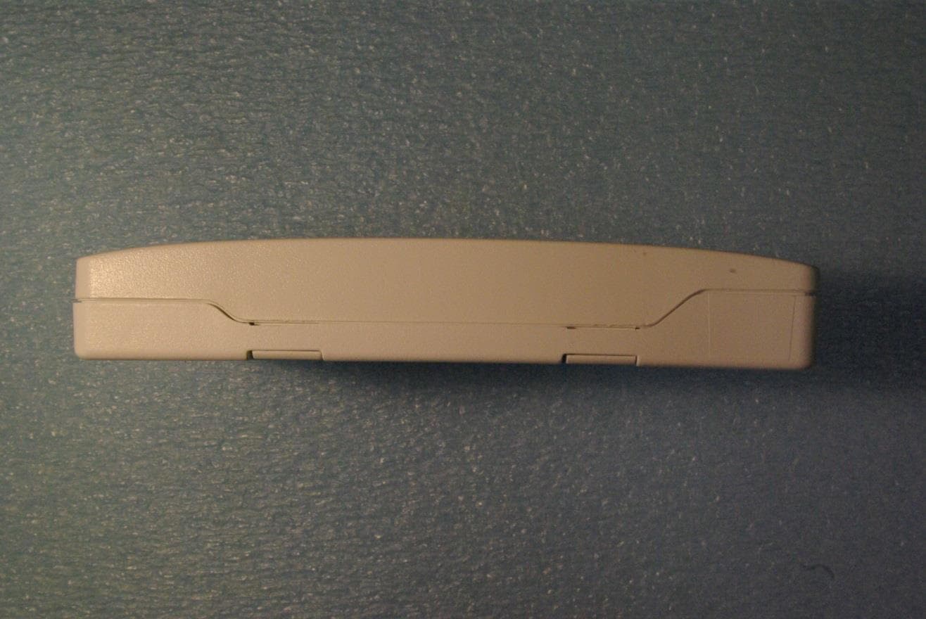
CCKPC0163
May 11, 2015Low Power Wireless Transceiver
Equipment Class
DXX - Part 15 Low Power Communication Device Transmitter