CCKPC0133LOW POWER TRANSCEIVER
Digital Monitoring Products Inc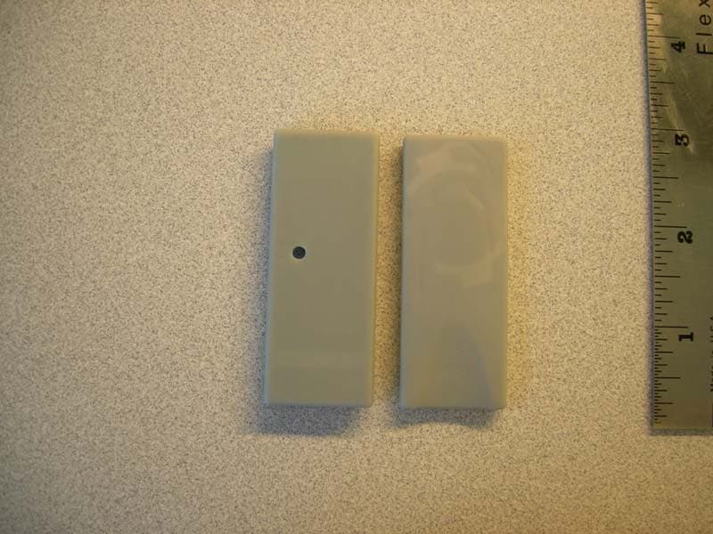
Click to zoom
Application Details
- Equipment Class
- DXT - Part 15 Low Power Transceiver, Rx Verified
- Date of Grant
- Nov 15, 2010
- Application Purpose
- Original Equipment
- Date of Application
- Nov 10, 2010
- Equipment Note
- LOW POWER TRANSCEIVER
- Frequency Range
- 903.00000000 - 927.00000000
- Country
- United States
Documents & Files
Document Text
Text extracted from the exhibit documents filed with the FCC. Open a document above to read the original.
Users Manual
InstallatIon GuIde 1107 Micro Window Transmitter Description The Model 1107 Micro Window Transmitter is a low profile 1100 Series transmitter for use on windows and powered by a 3V coin cell battery. It contains a single reed switch which detects a magnet. Compatibility All DMP 1100 Series Wireless Receivers and Panels What is Included The 1107 Micro Window Transmitter includes the following items: • One 1107 Transmitter PCB mounted in a two-part housing • Magnet with standard or commercial housing and base • One CR2430 3V Coin Cell Lithium Battery • Hardware pack and serial number label • Double-sided tape for transmitter and standard magnet housing Transmitter Serial Number For your convenience, an additional pre-printed serial number label is included. Prior to installing the device, record the serial number or place the pre-printed serial number label on the panel programming sheet. This number is required during programming. As needed, use the zone name and number label to identify a specific transmitter. Programming the Transmitter in the Panel Program the device as a zone in Zone Information during panel programming. At the Serial Number: prompt, enter the eight-digit serial number. Continue to program the zone as directed in the panel programming guide. Note: When a receiver is installed, powered up, or the panel is reset, the supervision time for transmitters is reset. If the receiver has been powered down for more than one hour, wireless transmitters may take up to an additional hour to send a supervision message unless tripped, tampered, or powered up. This operation extends battery life for transmitters. A missing message may display on the keypad until the transmitter sends a supervision message. Selecting the Proper Location (LED Survey Operation) The 1107 provides survey capability to allow one person to confirm transmitter communication with the receiver before installation. The 1107 Red Survey LED turns on whenever data is sent to the receiver then immediately turns off when the receiver acknowledgement is received. Using the contact magnet is a convenient way to send data to the receiver to confirm operation. When the magnet is moved away or brought towards the contact, the LED blinks once to indicate proper communication. When the transmitter does not receive an acknowledgement from the receiver the LED remains on for about 8 seconds to let you know communication is not established. Communication is also faulty when the LED flashes multiple times in quick succession. Relocate the contact or receiver until the LED immediately turns off indicating the transmitter and receiver are communicating properly. Proper communication between the transmitter and receiver is verified each time the magnet is moved within 1/2 inch of the transmitter or pulled away from the transmitter. Refer to the 1100 Series Receiver installation for full information about the survey LED. Mounting the Transmitter and Magnet Assembly The transmitter and magnet assembly should have no more than 1/2" space between the assembled housings after installation. When mounting on metal (ferrous) surfaces, this distance is slightly less. It is recommended the transmitter be mounted on the window frame and the magnet assembly be mounted on the window. Magnet Assembly Only one magnet assembly is required for internal reed switch operation. Depending on the installation requirements, either the Standard Magnet Assembly (Figure 3) or the Commercial Magnet Assembly (Figure 4) can be used. Snap the supplied magnet into the desired housing prior to mounting. Installing the Transmitter and Magnet 1. Remove the cover and battery if installed. See Fig. 1. 2. Hold the transmitter base in place with the reed switch nearest to the area where the magnet is to be mounted. Note: There is no need to remove the PCB from the housing during installation. 3. Use the supplied double-sided tape or place one supplied #4 flat head screw into the mounting hole location to secure the housing to the surface. 4. When using the standard magnet, place the magnet base on the surface nearest to the internal reed switch location aligning the location notches in the transmitter and magnet base (see Figure 5), and use the provided #4 flat head screws to secure the magnet base in place. Snap the magnet into the standard housing, then snap the housing onto the base. 5. When using the commercial magnet, snap the magnet into the commercial housing, then using the supplied #4 flat head screws, mount the magnet using the alignment notches as a guide (see Figure 6). Figure 2: 1107 PCB Layout Optional Mounting Hole Battery Location Internal Contact Magnetic Reed Switch Red Survey LED C R 2 4 3 0 Serial Number Figure 1: Transmitter and Magnet Standard Magnet Housing 1107 Transmitter Insert small screwdriver into notch and lift to remove cover. Do not twist. Notch Notch Notch Housing Base Magnet Magnet Housing #4 Flat Head Screws Alignment Notch Figure 3: Standard Magnet Assembly Magnet Housing Magnet #4 Flat Head Screws Alignment Notch Figure 4: Commercial Magnet Assembly LT-1156 © 2010 Digital Monitoring Products, Inc. 800-641-4282 www.dmp.com Made in the USA INTRUSION • FIRE • ACCESS • NETWORKS 2500 North Partnership Boulevard Springfield, Missouri 65803-8877 10445 Installing or Replacing the Battery Observe polarity when installing the battery, the positive (+) side up. Reversing the battery will damage the transmitter. Use a 3V coin cell lithium battery, DMP Model CR2430, or the equivalent battery from a local retail outlet. Note: When setting up a wireless system, it is recommended to program zones and connect the receiver before installing batteries in the transmitters. 1. If installed, remove the transmitter housing cover as shown in Figure 1. 2. If replacing the battery, remove the old battery and dispose of it properly. 3. Place the 3V coin cell lithium battery in the holder positive side up as shown in Figure 2 and press into place. 4. Snap the…
Text truncated - open the document above for the full version.
Cover Letter(s)
November 5, 2010 Timco Engineering Inc. 849 NW State Road 45 Newberry, FL 32669 Applicant: Digital Monitoring Products, Inc. 2500 North Partnership Boulevard Springfield, MO 65802 Re: Confidentiality for submittal information regarding FCC ID: CCKPC0133 PRODUCT: Low Power Transmitters operated under part 15.249 Dear Sirs: Digital Monitoring Products, Inc. requests that the material in the Schematics, Operational Description, block diagram, and parts list be withheld from public disclosure in accordance with Section 0.459 of the Commissions Rules, 47 C.F.R. 0.459, following grant of the application. In support of this request, Digital Monitoring Products, Inc. submits the following: CONFIDENTIAL FILES Conf BlkDia CCKPC0133.pdf Conf OpDes CCKPC0133.pdf Conf Schem CCKPC0133.pdf 1. Identification of the specific information for which confidential treatment is sought: The materials set fourth in the Operational Description, block diagram, parts list, and Schematics, which are segregated, from the non-confidential exhibits of the application, are those for which confidentiality is sought. 2. Identification of the Commission proceeding in which the information was submitted or a description of the circumstances giving rise to the submission: The proceeding is that involving the application for equipment authorization (certification) under FCC ID No: CCKPC0133 3. Explanation of the degree to which the information is commercial or financial, or contains a trade secret or is privileged: This material includes a detailed theory of operation, circuit diagrams, and schematic. As such, this material is treated as highly confidential business information. ROGERS LABS, INC. 4405 West 259 th Terrace Louisburg, KS 66053 4. Explanation of the degree to which the information concerns a service that is subject to competition: The material for which confidentiality is sought is employed in the design and manufacture of this transmitting equipment that is offered on a highly competitive basis. Customers for this equipment have a variety of competing sources. 5. Explanation of how disclosure of the information could result in substantial competitive harm: Disclosure would, in effect, give away the fruits of the labors of Digital Monitoring Products, Inc.’s engineering personnel, who have designed the equipment and the manufacturing process. Disclosure would also offer competitors additional unwarranted insight into the state of the product development, thereby allowing competitors an advantage, not available to Digital Monitoring Products, Inc. 6. Identification of any measures taken by the submitting party to prevent unauthorized disclosure: The information for which confidential treatment is sought is kept confidential by Digital Monitoring Products, Inc. and not made available to third parties except pursuant to non-disclosure agreements. 7. Identification of whether the information is available to the public and the extent of any previous disclosure of the information to third parties: To the knowledge of those preparing this application, the information has not been disclosed publicly heretofore. While the general theory of operation of this equipment has been the subject of numerous disclosures in industry and standards groups as well as in rule making proceedings of the FCC, the protection sought is narrowly drawn and pertains to certain specific implementations of this radio technology. 8. Justification of the period during which the submitting party asserts that the material should not be available for public disclosure: This material should not be disclosed for at least 25 years. While improvements in design are made relatively frequently, disclosure of the design information would lead to insights into both design and manufacturing techniques that could have an adverse competitive effect for many years to come. This equipment is designed for residential, commercial, industrial, and governmental applications. As such, it is important that the design not be made available to unauthorized persons who might attempt to use knowledge of the design to compromise the applications for which the equipment will be employed. Should you require any further information, please contact the undersigned. Thank you for your consideration in this matter. Sincerely, Scot Rogers
Cover Letter(s)
January 3, 2008 Federal Communications Commission Equipment Approval Services Post Office Box 358315 Pittsburgh, Pennsylvania 15215-5315 To Whom It May Concern: Please be advised that Digital Monitoring Products, Inc. has authorized Scot Rogers of Rogers Labs, Inc. to act on behalf in all matters relating to application for equipment authorization, including the signing of all documents relating to these matters and submittals. All acts carried out by Scot Rogers of Rogers Labs, Inc. on our behalf shall have the same effects as our own. Rogers Labs, Inc. authorized to receive and exchange data between our company and the Commission. This Authorization is made pursuant to Paragraph 2.911 of FCC Rules CFR 47. This Authorization is in effect until otherwise notified in writing. Best regards, Terry Shelton Product Quality Assurance Manager Digital Monitoring Products, Inc. Lb
Cover Letter(s)
November 5, 2010 Timco Engineering Inc. Federal Communications Commission 849 NW State Road 45 Equipment Approval Services Newberry, FL 32669 P.O. Box 35815, Pittsburgh, PA 15251-3315 Applicant: Digital Monitoring Products, Inc.Equipment: FCC ID: CCKPC0133 2500 North Partnership Boulevard CORES number: 0009 86 9348 Springfield, MO 65802 FCC Rules: Parts 2 and 15.249 Gentlemen The form 731 and application information have been electronically submitted and any attachments will be up loaded to your web site to be used in obtaining grant of certification. Confidentiality is requested as outlined below. Permanent Digital Monitoring Products, Inc. requests that the material in the Parts List, Schematics, block diagram, and Operational Description be withheld from public disclosure in accordance with Section 0.459 of the Commissions Rules, 47 C.F.R. 0.459, following grant of the application. It is requested that the information contained in the operational description, block diagram, parts list, and schematics of the application be held confidential per Section 0.459. A statement of confidentiality will be attached with the application at the time of submittal. Schematics Conf Schem CCKPC0133.pdf Block diagram Conf BlkDia CCKPC0133.pdf Operational Description Conf OpDes CCKPC0133.pdf Should you require any further information, please contact the undersigned. Thank you for your consideration in this matter. Sincerely, Scot Rogers Rogers Labs, Inc. Enclosures ROGERS LABS, INC. 4405 West 259 th Terrace Louisburg, KS 66053 Phone / Fax (913) 837-3214
External Photos
Rogers Labs, Inc. Digital Monitoring Products, Inc. 4405 West 259 th Terrace Model: 1107 FCC ID#: CCKPC0133 Louisburg, KS 66053 Test #:101103 SN: 2000002 IC: 5251A-PC0133 Phone/Fax: (913) 837-3214 Test to: FCC Parts 2 and 15.249, RSS-210 Date: November 3, 2010 Revision 1 File: ExtPho CCKPC0133 Page 1 of 1 External photographs of equipment under test
ID Label/Location Info
Rogers Labs, Inc. Digital Monitoring Products, Inc. 4405 West 259 th Terrace Model: 1107 FCC ID#: CCKPC0133 Louisburg, KS 66053 Test #:101103 SN: 2000002 IC: 5251A-PC0133 Phone/Fax: (913) 837-3214 Test to: FCC Parts 2 and 15.249, RSS-210 Date: November 3, 2010 Revision 1 File: LabelSmpl CCKPC0133 Page 1 of 1 FCC ID label and location Label
Internal Photos
Rogers Labs, Inc. Digital Monitoring Products, Inc. 4405 West 259 th Terrace Model: 1107 FCC ID#: CCKPC0133 Louisburg, KS 66053 Test #:101103 SN: 2000002 IC: 5251A-PC0133 Phone/Fax: (913) 837-3214 Test to: FCC Parts 2 and 15.249, RSS-210 Date: November 3, 2010 Revision 1 File: IntPho CCKPC0133 Page 1 of 1 Internal Photographs
Parts List/Tune Up Info
Rogers Labs, Inc. Digital Monitoring Products, Inc. 4405 West 259 th Terrace Model: 1107 FCC ID#: CCKPC0133 Louisburg, KS 66053 Test #:101103 SN: 2000002 IC: 5251A-PC0133 Phone/Fax: (913) 837-3214 Test to: FCC Parts 2 and 15.249, RSS-210 Date: November 3, 2010 Revision 1 File: TunPro CCKPC0133 Page 1 of 1 Each transmitter functionality is tested and judged using a pass or fail criteria during production. Units in compliance with the criteria continue through production and others are returned for diagnostics or disposal.
RF Exposure Info
Rogers Labs, Inc. Digital Monitoring Products, Inc. 4405 West 259 th Terrace Model: 1107 FCC ID#: CCKPC0133 Louisburg, KS 66053 Test #:101103 SN: 2000002 IC: 5251A-PC0133 Phone/Fax: (913) 837-3214 Test to: FCC Parts 2 and 15.249, RSS-210 Date: November 3, 2010 Revision 1 File: RFExp CCKPC0133 Page 1 of 1
Test Report
NVLAP Lab Code 200087-0 Rogers Labs, Inc. Digital Monitoring Products, Inc. 4405 West 259 th Terrace Model: 1107 FCC ID#: CCKPC0133 Louisburg, KS 66053 Test #:101103 SN: 2000002 IC: 5251A-PC0133 Phone/Fax: (913) 837-3214 Test to: FCC Parts 2 and 15.249, RSS-210 Date: November 3, 2010 Revision 1 File: DMP 1107 PC0133 TstRpt 101103 Page 1 of 34 APPLICATION SUBMITTAL REPORT FOR FCC And INDUSTRY CANADA GRANT OF CERTIFICATION FOR Model: 1107 PN: PC0133 902 - 928 MHz Transmitter FCC ID: CCKPC0133 IC: 5251A-PC0133 FOR DIGITAL MONITORING PRODUCTS, INC. 2500 North Partnership Boulevard Springfield, MO 65802-6310 Test Report Number: 101103 Authorized Signatory: Scot D. Rogers NVLAP Lab Code 200087-0 Rogers Labs, Inc. Digital Monitoring Products, Inc. 4405 West 259 th Terrace Model: 1107 FCC ID#: CCKPC0133 Louisburg, KS 66053 Test #:101103 SN: 2000002 IC: 5251A-PC0133 Phone/Fax: (913) 837-3214 Test to: FCC Parts 2 and 15.249, RSS-210 Date: November 3, 2010 Revision 1 File: DMP 1107 PC0133 TstRpt 101103 Page 2 of 34 ENGINEERING TEST REPORT FOR APPLICATION SUBMITTAL for GRANT of CERTIFICATION Per CFR47, PART 15C - INTENTIONAL RADIATORS Paragraph 15.249 and Industry Canada, RSS-210 Low Power Transmitter For DIGITAL MONITORING PRODUCTS, INC. 2500 North Partnership Boulevard Springfield, MO 65802-6310 Terry Shelton, Model: 1107 PN: PC0133 Frequency 902-928 MHz FCC ID#: CCKPC0133, IC: 5251A-PC0133 Test Date: November 3, 2010 Certifying Engineer: Scot D. Rogers Rogers Labs, Inc. 4405 West 259 th Terrace Louisburg, KS 66053 Phone: (913) 837-3214 Facsimile: (913) 837-3214 This report shall not be reproduced except in full, without the written approval of the laboratory. This report must not be used by the client to claim product endorsement by NVLAP, NIST, or any agency of the U.S. Government. ROGERS LABS, INC. 4405 West 259 th Terrace Louisburg, KS 66053 Phone / Fax (913) 837-3214 NVLAP Lab Code 200087-0 Rogers Labs, Inc. Digital Monitoring Products, Inc. 4405 West 259 th Terrace Model: 1107 FCC ID#: CCKPC0133 Louisburg, KS 66053 Test #:101103 SN: 2000002 IC: 5251A-PC0133 Phone/Fax: (913) 837-3214 Test to: FCC Parts 2 and 15.249, RSS-210 Date: November 3, 2010 Revision 1 File: DMP 1107 PC0133 TstRpt 101103 Page 3 of 34 Table of Contents TABLE OF CONTENTS .................................................................................................. 3 FORWARD ..................................................................................................................... 5 OPINION / INTERPRETATION OF RESULTS ............................................................... 5 ENVIRONMENTAL CONDITIONS.................................................................................. 5 APPLICATION FOR CERTIFICATION ........................................................................... 6 APPLICABLE STANDARDS & TEST PROCEDURES .................................................. 7 EQUIPMENT TESTED .................................................................................................... 7 EQUIPMENT FUNCTION AND TESTING PROCEDURES ............................................ 7 EQUIPMENT AND CABLE CONFIGURATIONS ........................................................... 8 Radiated Emission Test Procedure ..................................................................................................................... 8 UNITS OF MEASUREMENTS ........................................................................................ 8 TEST SITE LOCATIONS ................................................................................................ 8 LIST OF TEST EQUIPMENT .......................................................................................... 9 GENERAL EMISSIONS (UNINTENTIONAL RADIATORS) ......................................... 10 Radiated EMI ..................................................................................................................................................... 10 Figure One Plot of General Radiated Emissions ............................................................................................... 11 Figure Two Plot of General Radiated Emissions ............................................................................................... 11 Figure Three Plot of General Radiated Emissions ............................................................................................. 12 Figure Four Plot of General Radiated Emissions .............................................................................................. 12 Figure Five Plot of General Radiated Emissions ............................................................................................... 13 General Radiated Emissions Data from EUT .................................................................................................. 13 Summary of Results for Radiated Emissions ................................................................................................... 13 INTENTIONAL RADIATORS EMISSIONS ................................................................... 14 Antenna Requirements ...................................................................................................................................... 14 Restricted Bands of Operation .......................................................................................................................... 14 Radiated Emissions Data in Restricted Bands ................................................................................................... 15 NVLAP Lab Code 200087-0 Rogers Labs, Inc. Digital Monitoring Products, Inc. 4405 West 259 th Terrace Model: 1107 FCC ID#: CCKPC0133 Louisburg, KS 66053 Test #:101103 SN: 2000002 IC: 5251A-PC0133 Phone/Fax: (913) 837-3214 Test to: FCC Parts 2 and 15.249, RSS-210 Date: November 3, 2010 Revision 1 File: DMP 1107 PC0133 TstRpt 101103 Page 4 of 34 Summary of Results for Radiated Emissions in Restricted Bands ....................................…
Text truncated - open the document above for the full version.
Test Setup Photos
Rogers Labs, Inc. Digital Monitoring Products, Inc. 4405 West 259 th Terrace Model: 1107 FCC ID#: CCKPC0133 Louisburg, KS 66053 Test #:101103 SN: 2000002 IC: 5251A-PC0133 Phone/Fax: (913) 837-3214 Test to: FCC Parts 2 and 15.249, RSS-210 Date: November 3, 2010 Revision 1 File: TSup CCKPC0133 Page 1 of 1 Test setup photographs
Contact Information
Applicant
Brad Tucker(VP - Product Management and Support)
Test Firm
Rogers Labs, Inc.Scot Rogers
Technical Specifications
| # | Rule Parts | Frequency Range | Power Output |
|---|---|---|---|
| 1 | 15C | 903 MHz - 927 MHz | - |
Other Applications from Digital Monitoring Products Inc
CCKPC0245
Apr 23, 20231101 Receiver
Equipment Class
DSS - Part 15 Spread Spectrum Transmitter
CCKPC0241
Dec 29, 20221132 Recessed contact
Equipment Class
DSS - Part 15 Spread Spectrum Transmitter
CCKPC0114R9
May 10, 2021Life Safety and security wireless receiver.
Equipment Class
DSS - Part 15 Spread Spectrum Transmitter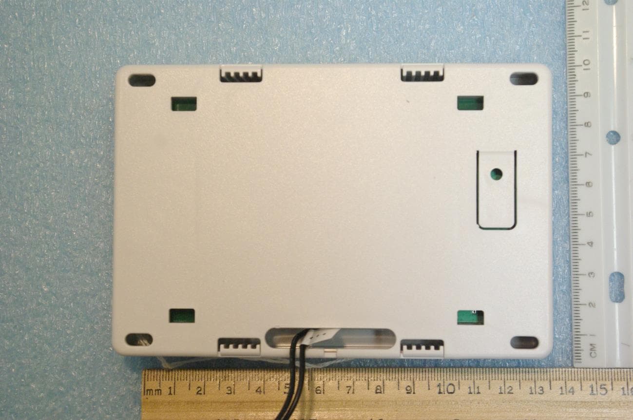
CCKPC0225
Jan 06, 2021900 MHz FHSS Transceiver System
Equipment Class
DSS - Part 15 Spread Spectrum Transmitter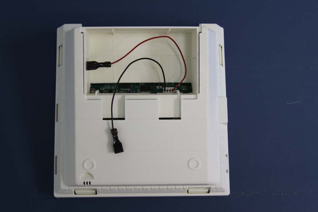
CCKPC0156
Oct 21, 2015Personal Emergency Response Base Unit
Equipment Class
DXX - Part 15 Low Power Communication Device Transmitter