CCKPC0166Low Power Wireless Transceiver
Digital Monitoring Products Inc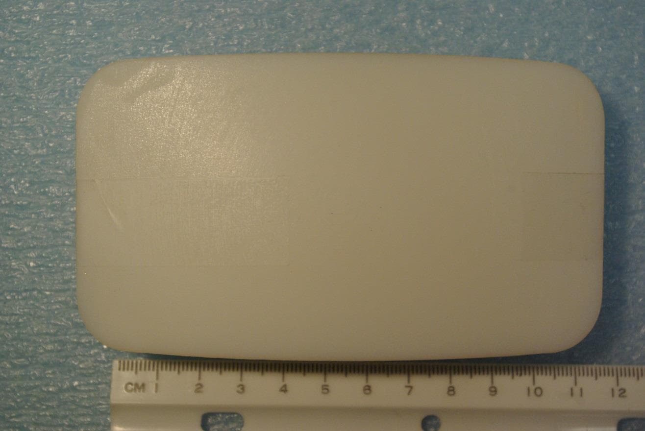
Click to zoom
Application Details
- Equipment Class
- DXX - Part 15 Low Power Communication Device Transmitter
- Date of Grant
- Apr 05, 2015
- Application Purpose
- Original Equipment
- Date of Application
- Apr 05, 2015
- Equipment Note
- Low Power Wireless Transceiver
- Frequency Range
- 903.00000000 - 927.00000000
- Country
- United States
Documents & Files
Document Text
Text extracted from the exhibit documents filed with the FCC. Open a document above to read the original.
Users Manual
InstallatIon GuIde 1137 Emergency Light Description The 1137 Emergency Light is a battery powered, wireless LED light activated by a loss of AC power output from your panel and may be used as a stair or path light. The 1137 operates using the supplied 3.0 Vdc Lithium batteries. Compatibility All DMP 1100 Series Wireless Receivers and Panels What is Included The 1137 Emergency Light includes the following: • One 1137 Emergency Light • Two 3.0 Vdc Lithium batteries • Serial number label Emergency Light Serial Number For your convenience, an additional pre-printed serial number label is included. Prior to installing the light, record the serial number or place the pre-printed serial number label on the 1137 base (see Figure 3). This number is required during programming. As needed, use the zone name and number label to identify a specific Emergency Light. Programming the Emergency Light in the Panel Refer to the panel programming guide as needed. Program the device as an AC Power Trouble Output in ZONE INFORMATION during panel programming. At the Serial Number prompt, enter the eight-digit serial number. Continue to program the zone as directed in the panel programming guide. LED Survey The 1137 Emergency Light provides a survey capability to allow one person to confirm communication with the receiver. The 1137 Emergency Light Status LED turns on whenever data is sent to the receiver then immediately turns off when the receiver acknowledgement is received. Pressing the button sends data to the receiver to confirm operation. When the Emergency Light does not receive an acknowledgement from the receiver the LED remains on for approximately eight seconds to indicate that communication is not established. Communication is also faulty when the LED flashes multiple times in quick succession. Relocate the light or receiver until the LED immediately turns off indicating the light and receiver are communicating properly. Proper communication between the light and receiver is verified when for each press of the button, the LED blinks immediately on and immediately off. Repeat this test to confirm five separate consecutive LED blinks. Any indication otherwise means proper communication has not been established. Figure 1: 1137 Emergency Light Figure 4: Installing the Top HousingFigure 3: Double-Sided Tape Mount SERIAL # Figure 2: Screw Mount Digital Monitoring Products 1137 Installation Guide 2 Mounting the Light These instructions cover installing the 1137 on an interior wall. Figures 2 and 3 show the base housing inside and outside views. Double-sided tape mounting 1. Install a 1/2” wide strip of double-sided tape (not included) in each of the indentations on the back of the base housing. 2. Remove the backing from the tape and place the housing in the desired location on the wall with the cover slot toward the bottom. See Figure 4. Screw mounting 1. Insert a flat screwdriver into the slot on the bottom of the 1137 cover housing and gently push down on the screwdriver handle while pulling the halves apart. See Figure 5. 2. Set aside the top housing containing the button and internal assembly. 3. Using two #6 Phillips head screws (not included), press through the depressions and mount the base to the wall. See Figure 2. 4. Align the top cover snap with the base and snap the bottom of the cover in place. See Figure 4. Installing or Replacing the Batteries Observe polarity when installing batteries. Use only 3.0 Vdc Lithium batteries, DMP Model CR123A, or the equivalent battery from a local retail outlet. Note: When setting up a wireless system, it is recommended to program zones and connect the receiver before installing batteries in the Emergency Lights. 1. Remove the top housing containing the PCB and lens assembly. Insert a flat screwdriver into the slot on the bottom of the housing and gently lift the screwdriver handle while pulling the halves apart. See Figure 5. 2. Using your hands, gently separate the top housing from the base. 3. Turn the top housing over and remove the old batteries. Dispose of the used batteries properly. See Figure 6 for battery location. 4. Observing polarity, place the 3.0 Vdc lithium batteries in the holders and press into place. 5. Snap the top housing back on to the base with PCB notch toward the top. See Figure 6. Caution: Properly dispose of used batteries. Do not recharge, disassemble, heat above 212°F (100°C), or incinerate. Risk of fire, explosion, and burns. Battery Life Expectancy Typical battery life expectancy for DMP Model 1137 Emergency Light is 2 years. DMP wireless equipment uses two-way communication to extend battery life. The following situations can reduce battery life expectancy: • If a receiver is unplugged, or not installed. Note: Emergency Lights continue to send supervision messages until a receiver returns an acknowledgement. After an hour the Emergency Light only attempts a supervision message every 60 minutes. • When installed in extreme hot or cold environments. The following situation can extend battery life expectancy: • Extend or remove Emergency Light supervision time in panel programming. Figure 6: Top Housing PCB and Battery Location Top PCB Snap Bottom PCB Snap PCB Support Serial Number Label Battery Holders PCB Support Bottom Cover Snap Top Cover Snap Figure 5: Removing the Cover 1137 Installation Guide Digital Monitoring Products 3 FCC Information This device complies with Part 15 of the FCC Rules. Operation is subject to the following two conditions: (1) This device may not cause harmful interference, and (2) this device must accept any interference received, including interference that may cause undesired operation. The antenna used for this transmitter must be installed to provide a separation distance of at least 20 cm (7.874 in.) from all persons. It must not be co-located or operated in conjunction with any other antenna or transmitter. Changes or modifications made by the user and not expressly approved by the party responsible…
Text truncated - open the document above for the full version.
Cover Letter(s)
January 3, 2008 Federal Communications Commission Equipment Approval Services Post Office Box 358315 Pittsburgh, Pennsylvania 15215-5315 To Whom It May Concern: Please be advised that Digital Monitoring Products, Inc. has authorized Scot Rogers of Rogers Labs, Inc. to act on behalf in all matters relating to application for equipment authorization, including the signing of all documents relating to these matters and submittals. All acts carried out by Scot Rogers of Rogers Labs, Inc. on our behalf shall have the same effects as our own. Rogers Labs, Inc. authorized to receive and exchange data between our company and the Commission. This Authorization is made pursuant to Paragraph 2.911 of FCC Rules CFR 47. This Authorization is in effect until otherwise notified in writing. Best regards, Terry Shelton Product Quality Assurance Manager Digital Monitoring Products, Inc. Lb
Cover Letter(s)
April 1, 2015 Regarding FCC ID label placement for the Model 1137 Emergency Light, IC: 5251A-PC0166 applications, DMP wishes to print the information directly onto the device printed circuit board. This location will ensure the end user is able to view the information before operation. The identifier will be readily viewable upon installation and each time the cover is removed. The equipment is sold and required to be mounted before operation thus exposing the information before operation. This location will help ensure the longevity of the information as this equipment may be in service in harsh environments. Best Regards, Terry Shelton | Director of Technical Design Digital Monitoring Products | dmp.com 417.831.9362 | Fax 417.447.9698 Lb
External Photos
Rogers Labs, Inc. Digital Monitoring Products, Inc. 4405 W. 259th Terrace Model: 1137 SN: ENG 1 FCC ID: CCKPC0166 Louisburg, KS 66053 Test #: 150316 IC: 5251A-PC0166 Phone/Fax: (913) 837-3214 Test to: FCC (15.249), RSS-210 Date: April 1, 2015 Revision 1 File: ExtPho 1137 Page 1 of 2 External photographs of equipment under test Rogers Labs, Inc. Digital Monitoring Products, Inc. 4405 W. 259th Terrace Model: 1137 SN: ENG 1 FCC ID: CCKPC0166 Louisburg, KS 66053 Test #: 150316 IC: 5251A-PC0166 Phone/Fax: (913) 837-3214 Test to: FCC (15.249), RSS-210 Date: April 1, 2015 Revision 1 File: ExtPho 1137 Page 2 of 2
ID Label/Location Info
Rogers Labs, Inc. Digital Monitoring Products, Inc. 4405 W. 259th Terrace Model: 1137 SN: ENG 1 FCC ID: CCKPC0166 Louisburg, KS 66053 Test #: 150316 IC: 5251A-PC0166 Phone/Fax: (913) 837-3214 Test to: FCC (15.249), RSS-210 Date: April 1, 2015 Revision 1 File: LabelSmpl 1137 Page 1 of 1 ID label and location Model FCC ID IC ID Label placement
Internal Photos
Rogers Labs, Inc. Digital Monitoring Products, Inc. 4405 W. 259th Terrace Model: 1137 SN: ENG 1 FCC ID: CCKPC0166 Louisburg, KS 66053 Test #: 150316 IC: 5251A-PC0166 Phone/Fax: (913) 837-3214 Test to: FCC (15.249), RSS-210 Date: April 1, 2015 Revision 1 File: IntPho 1148 Page 1 of 1 Internal Photographs
Parts List/Tune Up Info
Rogers Labs, Inc. Digital Monitoring Products, Inc. 4405 W. 259th Terrace Model: 1137 SN: ENG 1 FCC ID: CCKPC0166 Louisburg, KS 66053 Test #: 150316 IC: 5251A-PC0166 Phone/Fax: (913) 837-3214 Test to: FCC (15.249), RSS-210 Date: April 1, 2015 Revision 1 File: TunPro 1137 Page 1 of 1 Tune-up Procedure Each unit is evaluated during production and then given pass/fail status based on the measured parameters. The pass/fail threshold is determined by engineering during product development. Compliant samples continue through production and non-compliant units are removed.
Test Report
NVLAP Lab Code 200087-0 Rogers Labs, Inc. Digital Monitoring Products, Inc. 4405 W. 259th Terrace Model: 1137 SN: ENG 1 FCC ID: CCKPC0166 Louisburg, KS 66053 Test #: 150316 IC: 5251A-PC0166 Phone/Fax: (913) 837-3214 Test to: FCC (15.249), RSS-210 Date: April 1, 2015 Revision 1 File: DMP 1137 TstRpt 150316 d1 Page 1 of 26 Application Submittal Report FOR FCC And Industry Canada Grant Of Certification FOR Model: 1137 903-927 MHz Low Power Transmitter FCC ID: CCKPC0166 IC: 5251A-PC0166 FOR Digital Monitoring Products, Inc. 2500 North Partnership Boulevard Springfield, MO 65802-6310 Test Report Number: 150316 IC Test Site Registration: 3041A-1 Authorized Signatory: Scot D. Rogers NVLAP Lab Code 200087-0 Rogers Labs, Inc. Digital Monitoring Products, Inc. 4405 W. 259th Terrace Model: 1137 SN: ENG 1 FCC ID: CCKPC0166 Louisburg, KS 66053 Test #: 150316 IC: 5251A-PC0166 Phone/Fax: (913) 837-3214 Test to: FCC (15.249), RSS-210 Date: April 1, 2015 Revision 1 File: DMP 1137 TstRpt 150316 d1 Page 2 of 26 Engineering Test Report For Application Submittal for Grant of Certification FOR CFR 47, PART 15C - Intentional Radiators Paragraph 15.249 and Industry Canada, RSS-210 License Exempt Intentional Radiator For Digital Monitoring Products, Inc. 2500 North Partnership Boulevard Springfield, MO 65802-6310 Model: 1137 Low Power Transmitter Frequency Range 903-927 MHz FCC ID#: CCKPC0166 IC: 5251A-PC0166 Test Date: March 16, 2015 Certifying Engineer: Scot D. Rogers Rogers Labs, Inc. 4405 West 259 th Terrace Louisburg, KS 66053 Telephone/Facsimile: (913) 837-3214 This report shall not be reproduced except in full, without the written approval of the laboratory. This report must not be used by the client to claim product certification, approval, or endorsement by NVLAP, NIST, or any agency of the Federal Government. ROGERS LABS, INC. 4405 West 259 th Terrace Louisburg, KS 66053 Phone / Fax (913) 837-3214 NVLAP Lab Code 200087-0 Rogers Labs, Inc. Digital Monitoring Products, Inc. 4405 W. 259th Terrace Model: 1137 SN: ENG 1 FCC ID: CCKPC0166 Louisburg, KS 66053 Test #: 150316 IC: 5251A-PC0166 Phone/Fax: (913) 837-3214 Test to: FCC (15.249), RSS-210 Date: April 1, 2015 Revision 1 File: DMP 1137 TstRpt 150316 d1 Page 3 of 26 Table Of Contents TABLE OF CONTENTS .................................................................................................. 3 REVISIONS ..................................................................................................................... 4 FORWARD ..................................................................................................................... 5 OPINION / INTERPRETATION OF RESULTS ............................................................... 5 STATEMENT OF MODIFICATIONS AND DEVIATIONS ............................................... 5 EQUIPMENT TESTED .................................................................................................... 6 EQUIPMENT FUNCTION AND CONFIGURATION........................................................ 6 Equipment Configuration.................................................................................................................................... 6 APPLICATION FOR CERTIFICATION ........................................................................... 7 APPLICABLE STANDARDS & TEST PROCEDURES .................................................. 8 EQUIPMENT TESTING PROCEDURES ........................................................................ 8 AC Line Conducted Emission Test Procedure .................................................................................................. 8 Radiated Emission Test Procedure ..................................................................................................................... 8 Diagram 1 Test arrangement for radiated emissions of tabletop equipment ........................................................ 9 Diagram 2 Test arrangement for radiated emissions tested on Open Area Test Site (OATS) ........................... 10 TEST SITE LOCATIONS .............................................................................................. 10 LIST OF TEST EQUIPMENT ........................................................................................ 11 UNITS OF MEASUREMENTS ...................................................................................... 12 ENVIRONMENTAL CONDITIONS................................................................................ 12 INTENTIONAL RADIATORS ........................................................................................ 12 Antenna Requirements ...................................................................................................................................... 12 Restricted Bands of Operation .......................................................................................................................... 12 Table One Radiated Emissions in Restricted Bands Data ................................................................................. 13 NVLAP Lab Code 200087-0 Rogers Labs, Inc. Digital Monitoring Products, Inc. 4405 W. 259th Terrace Model: 1137 SN: ENG 1 FCC ID: CCKPC0166 Louisburg, KS 66053 Test #: 150316 IC: 5251A-PC0166 Phone/Fax: (913) 837-3214 Test to: FCC (15.249), RSS-210 Date: April 1, 2015 Revision 1 File: DMP 1137 TstRpt 150316 d1 Page 4 of 26 Summary of Results for Radiated Emissions in Restricted Bands ................................................................ 13 AC Line Conducted Emissions Procedure ....................................................................................................... 13 General Radiated EMI Testing Procedure ...................................................................................................... 14 Table Two General Radiated Emissions Data (worst-case) ............................................................................... 15 Summary of Results for General Radiated Emission…
Text truncated - open the document above for the full version.
Test Setup Photos
Rogers Labs, Inc. Digital Monitoring Products, Inc. 4405 W. 259th Terrace Model: 1137 SN: ENG 1 FCC ID: CCKPC0166 Louisburg, KS 66053 Test #: 150316 IC: 5251A-PC0166 Phone/Fax: (913) 837-3214 Test to: FCC (15.249), RSS-210 Date: April 2, 2015 Revision 1 File: TSup 1137 Page 1 of 3 Test setup photographs Rogers Labs, Inc. Digital Monitoring Products, Inc. 4405 W. 259th Terrace Model: 1137 SN: ENG 1 FCC ID: CCKPC0166 Louisburg, KS 66053 Test #: 150316 IC: 5251A-PC0166 Phone/Fax: (913) 837-3214 Test to: FCC (15.249), RSS-210 Date: April 2, 2015 Revision 1 File: TSup 1137 Page 2 of 3 Rogers Labs, Inc. Digital Monitoring Products, Inc. 4405 W. 259th Terrace Model: 1137 SN: ENG 1 FCC ID: CCKPC0166 Louisburg, KS 66053 Test #: 150316 IC: 5251A-PC0166 Phone/Fax: (913) 837-3214 Test to: FCC (15.249), RSS-210 Date: April 2, 2015 Revision 1 File: TSup 1137 Page 3 of 3
Contact Information
Applicant
Brad Tucker(VP - Product Management and Support)
Test Firm
Rogers Labs, Inc.Scot Rogers
Technical Specifications
| # | Rule Parts | Frequency Range | Power Output |
|---|---|---|---|
| 1 | 15C | 903 MHz - 927 MHz | - |
Other Applications from Digital Monitoring Products Inc
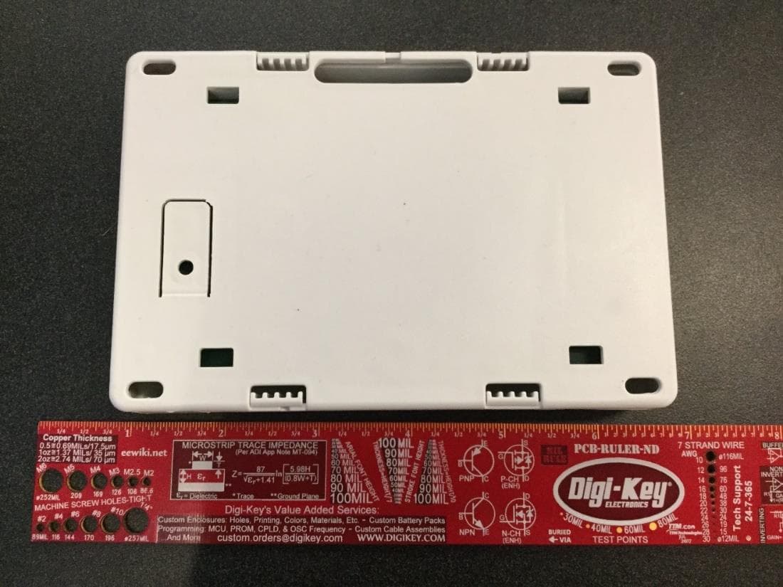
CCKPC0245
Apr 23, 20231101 Receiver
Equipment Class
DSS - Part 15 Spread Spectrum Transmitter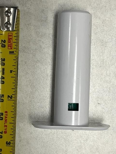
CCKPC0241
Dec 29, 20221132 Recessed contact
Equipment Class
DSS - Part 15 Spread Spectrum Transmitter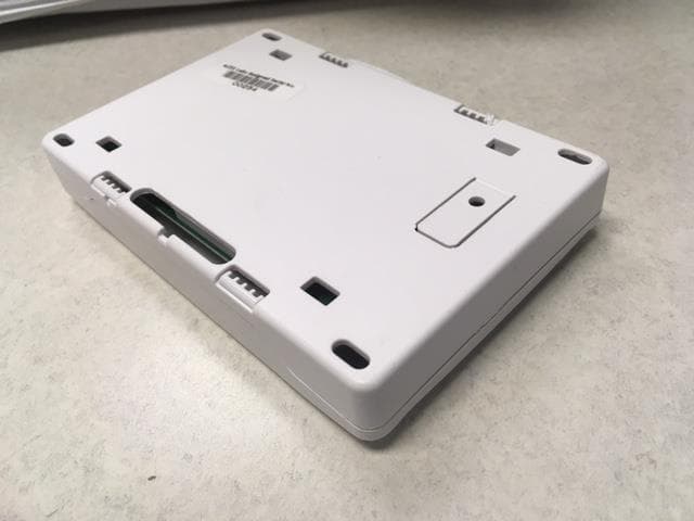
CCKPC0114R9
May 10, 2021Life Safety and security wireless receiver.
Equipment Class
DSS - Part 15 Spread Spectrum Transmitter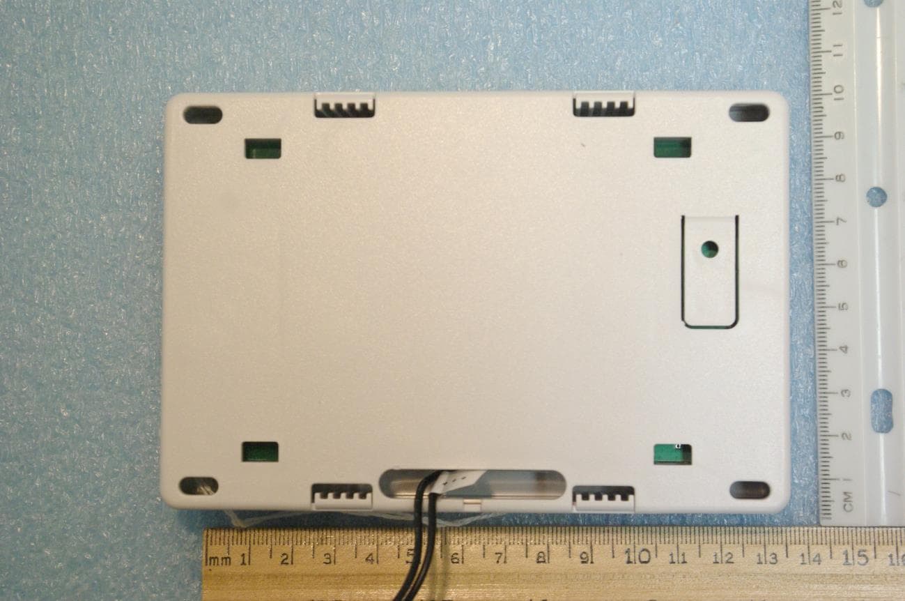
CCKPC0225
Jan 06, 2021900 MHz FHSS Transceiver System
Equipment Class
DSS - Part 15 Spread Spectrum Transmitter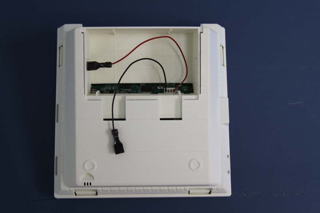
CCKPC0156
Oct 21, 2015Personal Emergency Response Base Unit
Equipment Class
DXX - Part 15 Low Power Communication Device Transmitter