DZL201544Wireless PC Camera Transmitter
Logitech Inc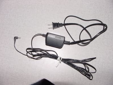
Click to zoom
Application Details
- Equipment Class
- DXX - Part 15 Low Power Communication Device Transmitter
- Date of Grant
- Jul 15, 2002
- Application Purpose
- Original Equipment
- Date of Application
- Jul 15, 2002
- Equipment Note
- Wireless PC Camera Transmitter
- Frequency Range
- 2415.00000000 - 2468.50000000
- Company
- Logitech Inc
- Country
- United States
Documents & Files
Document Text
Text extracted from the exhibit documents filed with the FCC. Open a document above to read the original.
Users Manual
QuickCam ® Cordless Setup ii © 2002 Logitech. All Rights Reserved. Logitech, the Logitech logo, and other Logitech marks are owned by Logitech and may be registered. All other trademarks are the property of their respective owners. Logitech assumes no responsibility for any errors that may appear in this manual. Information contained herein is subject to change without notice. Part Number: 623021-0914 FCC Compliance and Advisory Statement. This hardware device complies with Part 15 of the FCC Rules. Operation is subject to the following two conditions: 1) this device may not cause harmful interference, and 2) this device must accept any interference received, including interference that may cause undesired operation. This equipment has been tested and found to comply with the limits for a Class B digital device, pursuant to Part 15 of the FCC Rules. These limits are designed to provide reasonable protection against harmful interference in a residential installation. This equipment generates, uses, and can radiate radio frequency energy and, if not installed or used in accordance with the instructions, may cause harmful interference to radio communications. However, there is no guarantee that interference will not occur in a particular installation. If this equipment does cause harmful interference to radio or television reception, which can be determined by turning the equipment off and on, the user is encouraged to try to correct the interference by one or more of the following measures: 1) reorient or relocate the receiving antenna; 2) increase the separation between the equipment and the receiver; 3) connect the equipment to an outlet on a circuit different from that to which the receiver is connected; 4) consult the dealer or an experienced radio/TV technician for help. Any changes or modifications not expressly approved by the party responsible for compliance could void the user's authority to operate the equipment. Where shielded interface cables have been provided with the product or specified additional components or accessories elsewhere defined to be used with the installation of the product, they must be used in order to ensure compliance with FCC regulations. Canadian DOC Statement. This digital device does not exceed the Class B limits for radio noise emissions from digital apparatus specified in the interference-causing equipment standard entitled “Digital Apparatus,” ICES-003 of the Department of Communications. This device complies with RSS-210 of Industry and Science Canada. Operation is subject to the following two conditions: 1) this device may not cause interference, and 2) this device must accept any interference, including interference that may cause undesired operation of the device. © 2002 Logitech. Tous droits réservés. Logitech, le logo Logitech et les autres marques Logitech sont la propriété exclusive de Logitech et sont susceptibles d’être des marques déposées. Toutes les autres marques sont la propriété exclusive de leurs détenteurs respectifs. Logitech décline toute responsabilité en cas d'erreurs dans ce manuel. Les informations énoncées dans le présent document peuvent faire l’objet de modifications sans avis préalable. Déclaration FCC. Cet équipement a été testé et déclaré conforme à la section 15 du règlement de la FCC. Son fonctionnement est soumis aux conditions suivantes: 1) l'équipement concerné ne doit pas causer d'interférences dangereuses, et 2) il doit accepter toute interférence reçue, y compris les interférences risquant d'engendrer un fonctionnement indésirable. Cet équipement a été testé et déclaré conforme aux limitations prévues dans le cadre de la catégorie B des appareils numériques défini par la section 15 du règlement de la FCC. Ces limitations sont stipulées aux fins de garantir une protection raisonnable contre les interférences gênantes en installation résidentielle. Cet équipement génère, utilise et diffuse des ondes radio, et s'il n'est pas installé ni utilisé en conformité avec les instructions dont il fait l'objet, peut causer des interférences gênantes avec les communications radio. Cependant, nous ne pouvons vous garantir qu'une interférence ne se produira pas dans une installation particulière. Si cet équipement produit des interférences graves lors de réceptions radio ou télévisées qui peuvent être détectées en allumant et en éteignant l'équipement, vous êtes invités à les supprimer de plusieurs manières: 1) Réorienter ou déplacer l'antenne de réception; 2) Augmenter la distance séparant l'équipement et le récepteur; 3) Connecter l'équipement à un circuit différent de celui auquel le récepteur est connecté; 4) Contacter votre revendeur ou un technicien radio/TV qualifié. Toutes modifications ou tous changements effectués sans l'accord exprès de la partie responsable de la conformité aux normes pourraient contraindre l'utilisateur à ne plus utiliser son équipement. Afin d'assurer la conformité avec les règlements FCC, les câbles d'interface blindés fournis avec le produit doivent être utilisés, ainsi que tout autres composants ou accessoires également spécifiés, lors de l'installation du produit. Déclaration du Ministère des Communications Canadien. Cet appareil numérique est conforme aux limitations concernant l'émission d'interférences radio par des appareils numériques de catégorie B, telles que stipulées dans le cadre de la norme Appareils numériques ICES-003 édictée par le Ministère canadien de l’Industrie. Cet équipement a été déclaré conforme à la norme RSS-210 édictée par le Ministère canadien des Sciences et de l'Industrie. Son fonctionnement est soumis aux conditions suivantes: 1) l'équipement concerné ne doit pas causer d'interférences, et 2) il doit accepter toute interférence reçue, y compris les interférences risquant d'engendrer un fonctionnement indésirable. iii iv v Contents English . . . . . . . . . . . . . . . . . . . . . . . . . . . . . . . . . . . . . . . . . . . . . . . . . . . . . . . . . . . . . . 1 De…
Text truncated - open the document above for the full version.
Block Diagram
Cordless QuickCam Block Diagram for EMI evaluation P. Thompson 6-17-02 Microprogrammer f xtal = 8.064 MHz f max =8.064 MHz FM Modulator f xtal = 8 MHz 2400 to 2483 MHz Video Amp 0 to 6 MHz Sensor and NTSC f xtal = 14.3 MHz fmax= 14.3 MHz Power Amp 2400 to 2483 MHz Audio Modulator f xtal = 8 MHz 5.97 to 6.03 MHz DRAM Microprogrammer f xtal = 8.064 MHz f max =8.064 MHz NTSC to YUV f xtal = 27 MHz f max =54 MHz Audio Codec f xtal = 24.576 fmax=24.576 USB and Compress f xtal = 48 MHz f max =48 MHz LNA 2400 to 2488 MHz Local Osc. f xtal = 8.00 MHz 1920 to 2003 MHz Mixer 2400 to 2488 MHz IF 480 MHz 472 to 496 MHz Video Demod. f lc = 480MHz 472 to 496 MHz LC osc Video Amp. 0 to 6 MHz Audio Demod. F ceram = 6.00 MHz 5.97 to 6.03 MHz USB Camera Receiver Digital Data BusDigital Data Bus
Cover Letter(s)
Intertek Testing Services NA Inc. 7250 Hudson Blvd., Suite 100 Oakdale, MN 55128 Tele :(650) 463-2900 Bharat Shah July 2, 2002 Sub. Request for Making some information Confidential on FCC file for FCC ID # DZL201544 Hello, Could you please make following information confidential on Logitech File? 1. Circuit diagram It proprietary circuit and we do not want our competitor to see this information. Thank you for your anticipated assistance. Regards, Bharat Shah EMC Engineer 6505 Kaiser Drive Fremont, CA 94555 Voice: 510-713-4777 Fax: 419-828-4405
External Photos
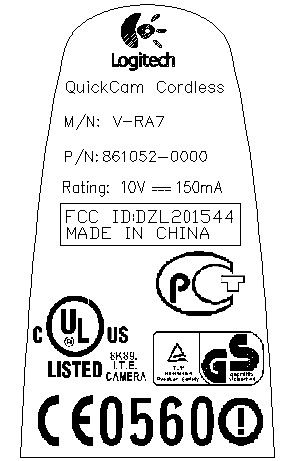
1365 Adams Court Menlo Park, CA 94025 Logitech Inc, Model No. V-RA7 FCC ID: DZL201544 1365 Adams Court Menlo Park, CA 94025 Logitech Inc, Model No. V-RA7 FCC ID: DZL201544 1365 Adams Court Menlo Park, CA 94025 Logitech Inc, Model No. V-RA7 FCC ID: DZL201544 1365 Adams Court Menlo Park, CA 94025 Logitech Inc, Model No. V-RA7 FCC ID: DZL201544 1365 Adams Court Menlo Park, CA 94025 Logitech Inc, Model No. V-RA7 FCC ID: DZL201544 1365 Adams Court Menlo Park, CA 94025 Logitech Inc, Model No. V-RA7 FCC ID: DZL201544
Internal Photos
1365 Adams Court Menlo Park, CA 94025 Logitech Inc, Model No. V-RA7 FCC ID: DZL201544 1365 Adams Court Menlo Park, CA 94025 Logitech Inc, Model No. V-RA7 FCC ID: DZL201544 1365 Adams Court Menlo Park, CA 94025 Logitech Inc, Model No. V-RA7 FCC ID: DZL201544 1365 Adams Court Menlo Park, CA 94025 Logitech Inc, Model No. V-RA7 FCC ID: DZL201544 1365 Adams Court Menlo Park, CA 94025 Logitech Inc, Model No. V-RA7 FCC ID: DZL201544 1365 Adams Court Menlo Park, CA 94025 Logitech Inc, Model No. V-RA7 FCC ID: DZL201544 1365 Adams Court Menlo Park, CA 94025 Logitech Inc, Model No. V-RA7 FCC ID: DZL201544 1365 Adams Court Menlo Park, CA 94025 Logitech Inc, Model No. V-RA7 FCC ID: DZL201544 1365 Adams Court Menlo Park, CA 94025 Logitech Inc, Model No. V-RA7 FCC ID: DZL201544 1365 Adams Court Menlo Park, CA 94025 Logitech Inc, Model No. V-RA7 FCC ID: DZL201544 1365 Adams Court Menlo Park, CA 94025 Logitech Inc, Model No. V-RA7 FCC ID: DZL201544 1365 Adams Court Menlo Park, CA 94025 Logitech Inc, Model No. V-RA7 FCC ID: DZL201544
Operational Description
7/10/02Revision 1.1 201545 Truckee 2.4GHz FM TV Transmitter RF Module operational Description and Specification V ALON T ECHNOLOGY , LLC1of 47/10/02 sdr 1.0 General Description: The Truckee 2.4GHz FM Transmitter is an RF module that is capable transmitting video and audio NTSC or PAL television signals in the 2400-2485MHz ISM frequency band. The transmitter accepts a composite video signal from any video source. The transmitter also accepts audio from any high level source. The transmit RF output frequency and audio sub-carrier frequency are set by the 3-wire, serial interface. Output power this transmitter is approximately 1mW. 2.0 Transmitter Topology Figure 1 above; shows the block of the FM transmitter topology. The transmitter is essentially PLL stabilized VCO, operating at the output frequency, that is a directly modulated by the video signal. The VCO is controlled by a PLL and tuneable over the 2400- 2485MHz ISM band. The input composite video signal is filtered by a video pre-emphasis network and applied to tuning port of the RF VCO to provide wideband FM modulation. The video deviation is not adjustable and is set by design. The RF VCO is controlled by the RF section of the dual synthesizer/PLL integrated circuit. This is a integer-N PLL with very low loop bandwidth. The audio signal is filtered by an audio pre-emphasis network and applied directly to the one of the two tuning ports of the 6.0MHz sub-carrier VCO to provide an FM modulated audio sub-carrier. The audio deviation is set by design. The frequency of the sub- carrier VCO is tuned and stabilized by the digital synthesizer/PLL through the other VCO tuning port. The 6 MHz audio sub-carrier is then amplitude limited by the diode limiter circuit in order to maintain a constant sub-carrier level. The limited sub-carrier signal is then amplified and buffered by the sub-carrier buffer amplifier in order to increase the signal level and isolate the VCO. The buffered sub-carrier is then filtered to remove harmonics by a narrow band bandpass filter. A secondary output from the buffer amplifier is further amplified and amplitude limited by the PLL Amp. The PLL Amp squares and limits the amplitude of the 6.0MHz sub-carrier signal in order to ensure positive clocking of the Synthesizer/PLL. The filtered sub-carrier output from the bandpass filter is combined with the pre-emphasised video signal, and the buffered RF loop filter signal at the summing node at the VCO tuning port. The summing node is simply a resistive adder circuit that combines the tuning signal with the video and audio sub-carrier modulation in the correct proportion for proper deviation and frequency control of the VCO. The RF VCO output at 2.4GHz is further amplified to provide an output level of approximately -0dBm to the antenna. The output lowpass filter removes the harmonics created by the VCO and amplifiers. The antenna is a dipole antenna realised on a FR4 PCB with about 1dBi gain. Figure 1 Antenna Video In 2.4GHz PA 2.4GHz VCO 3-wire serial frequency control Dual Synthesizer/PLL 8MHz Reference Audio In Video pre-emphasis Audio pre-emphasis 6 MHz VCO Limiter 6MHz BPF Harmonic LPF Test-port/ Switch Buffer/Amp PLL Amp 6MHz VCO loop filter 2.4GHz VCO loop filter filter switch loop filter buffer 7/10/02Revision 1.1 201545 Truckee 2.4GHz FM TV Transmitter RF Module operational Description and Specification V ALON T ECHNOLOGY , LLC2of 47/10/02 sdr The RF and sub carrier VCOs are controlled an integer-N PLL locked to the 8.00MHz crystal reference. The PLL is programmed via the 3-wire serial interface. The 8.00MHz crystal reference is provided by a single transistor discrete crystal oscillator. Measurement conditions Ambient temperature range: 0 to 40°C 3.0 Input dc Power DescriptionValueLimit / ToleranceUnits 3.1Input dc Voltage 3.3 ±10 V 3.2 Input current 44<50mA 3.3Noise (dc-10MHz BW)-<200 uV RMS 4.0 RF Specification DescriptionValueLimit / ToleranceUnits 4.1RF Output Frequency Range2400-2485min-maxMHz 4.2Tuning Increment50-kHz 4.3Frequency accuracy and stability- ±100 ppm 4.4Lock time<100mS 4.5Antenna port Output impedance50- Ω 4.6Antenna port VSWR1.00:1<2:1- 4.7Output power 0dBm ±1.5 (tbd) dB 4.8Harmonics (FCC 15.249 limits) typ. <-50<-40dBc 4.9Spurious output (FCC 15.249 Limits)typ. <-60<-50dBc 5.0 Video Specification DescriptionValueLimit / ToleranceUnits 5.1Video input voltage (single ended)0.5-V pk-pk 5.2Video input impedance4.5K>4.0K Ω 5.3 Video frequency response (after CCIT-405 equalization) 30Hz-4.2MHz reference at 500kHz 10Hz-4.2MHz -±0.5 ±1.5 dB 5.4 Video pre-emphasisCCIT-405 standard 5.5 Video modulation deviation (peak) Modulation slope is positive (positive voltage swing results in highe r frequency) 10kHz @ 1.0Vpk-pk 100kHz @ 1.0Vpk-pk 1MHz@ 1.0Vpk-pk MHz 5.6Video signal to noise ratiodB 5.7Luminance pulse response 2t P&B - <1% 5.8Color differential phase- <1deg. 5.9Color differential gain-<1% 5.10APL response per field residual-% 5.11Group delay 30Hz-4.2MHz- <±100 nS 6.0 Audio System Specifications DescriptionValueLimit / Tolerance Units 6.1Audio input Voltage (Maximum)500<1000mV p-p 6.2Audio input impedance100>50 KΩ 6.3 Audio total harmonic distortion (THD) 500mV pk-pk sine wave at 1kHz0.4<1.0% 6.4 Audio Sub-carrier level -25 tbddB 6.5Audio S/N>70dB 6.6 Audio frequency response 100-8kHz reference at 1kHz 0 ±1 dB 6.7Audio pre-emphasis50uS 6.8 Deviation (FM) for audio frequencies below pre-emphasis break- point . at 1kHz 23 ±2.3 kHz pk 7/10/02Revision 1.1 201545 Truckee 2.4GHz FM TV Transmitter RF Module operational Description and Specification V ALON T ECHNOLOGY , LLC3of 47/10/02 sdr 6.9Audio sub carrier frequency6.0 ±30 kHz 8.0 Interface and Channel Programming. The tuning of the transmitter is accomplished by programming the RF and audio PLL though the 3-wire serial interface. The tables below show the programming information for the local oscillator PLL programming. A fourth signal, SDO is used to read the internal state of the synthesiser. T…
Text truncated - open the document above for the full version.
Test Report
TEST REPORT Report Number: 30264991 Project Number: 3026499 ReportDate: June 25, 2002 Testing performed on the Wireless PC Camera transmitter Model Number: V -RA 7 FCC ID: DZL201544 to FCC Part 15.249 for Logitech, Inc. Test Performed by: Intertek Testing Services 1365 Adams Court Menlo Park, CA 94025 Test Authorized bv: Logitech 6505 Kaiser Dr . Fremont, CA 94555 Warnock Hersey --- .ie- ~/23/()Z Date: ..6~.." ".. ~ Prepared by: ~IJ {!/il;t"o~ J<:. David Chernomordik =;~iewed o-;J2/. ~" ~, OllieMoyrong O O G>()f5(a1.-- Date: enx:c l Intertek Testing Services NA, Inc. 1365 Adams Court, Menlo Park. CA 94025 Telephone 650-463-2900 Fax 650-463-2910 Home Page www.etlsemko.com Intertek Testing Services EMC Report for Logitech Inc. on the V-RA7, FCC ID: DZL201544 File: 30264991, FCC Part 15.249Page 2 of 25 TABLE OF CONTENTS 1.0Summary of Tests.......................................................................................................................3 2.0General Description....................................................................................................................4 2.1Product Description.........................................................................................................4 2.2Related Submittal(s) Grants..............................................................................................5 2.3Test Methodology............................................................................................................5 2.4Test Facility....................................................................................................................5 3.0System Test Configuration..........................................................................................................6 3.1Support Equipment and description...................................................................................6 3.2Block Diagram of Test Setup............................................................................................7 3.3Justification.....................................................................................................................8 3.4Software Exercise Program...............................................................................................8 3.5Mode of operation during test...........................................................................................8 3.6Modifications required for Compliance..............................................................................8 3.7Additions, deviations and exclusions from standards..........................................................8 4.0Measurement Results..................................................................................................................9 4.1Transmitter Radiated Emissions........................................................................................9 4.2AC Line Conducted Emission.........................................................................................12 4.3Out of Band Emission Plots............................................................................................17 5.0Antenna Requirement...............................................................................................................23 6.0List of test equipment...............................................................................................................24 7.0Document History.....................................................................................................................25 Intertek Testing Services EMC Report for Logitech Inc. on the V-RA7, FCC ID: DZL201544 File: 30264991, FCC Part 15.249Page 3 of 25 1.0 Summary of Tests TESTREFERENCERESULT Field Strength of Fundamental15.249aComplies Field Strength of Harmonics15.249aComplies Radiated Emissions outside the band15.249cComplies Radiated Emissions in restricted bands15.205Complies Line Conducted Emissions15.207Complies Antenna requirement15.203Complies Intertek Testing Services EMC Report for Logitech Inc. on the V-RA7, FCC ID: DZL201544 File: 30264991, FCC Part 15.249Page 4 of 25 2.0General Description 2.1 Product Description EUT is a wireless video camera. The camera can be used within a 75-foot radius (minimum) of the host PC in a home or office environment. • A wireless PC Camera for the High End retail market segment. • Wireless camera has an integral antenna, microphone, 4 channel selection, viewfinder with integrated siting/tally/streaming LED, on/off power pushbutton, LCM display for status, pushbutton shutter switch, battery and wall adapter power jack. • Indoor use only. • Camera uses a “desktop” power adapter of 12-foot total length with 3’ to mains and 9’ to camera. • Camera case design supports a fixed antenna not to exceed 57 x 10 x 3 mm in size. • Camera horizontal Field of View when pointed straight: 45 ± 3 degrees. • Low-battery indication: 3 level ICON will display battery life. • Camera will automatically power down after 5 minutes if the LCM mode is set to “Auto-off” and the AC adapter is not plugged into the camera or a video is not being captured. This feature can be overridden. • A battery connection that allows a “9 Volt” rectangular type of battery to power the camera. • Battery life, for a standard alkaline battery must be greater than 2 hours continuous service. Overview of the EUT Applicant name & address Logitech Inc. 6505 Kaiser Drive Fremont, CA 94555, USA Manufacturer name & address Suzhou Logitech Electronic, Ltd. No. 168 Bin He Road Standard Plant Suzhou City, P.R.C. Trade Name & Model No.Model # V-RA7 FCC IdentifierDZL201544 Use of ProductA wireless PC Camera for the High End retail market segment Type of TransmissionAnalog Type of Modulation Video modulation: FM, BW: 8 MHz Audio modulation: FM, BW:10 kHz Rated RF Output Output1 mW Frequency Range2415 – 2468.5 MHz Number of Channel(s)4 selectable channels Antenna(s) & Gainpermanently connected antenna, dipole type, 1 dBi gain, omni- directional …
Text truncated - open the document above for the full version.
Test Setup Photos
1365 Adams Court Menlo Park, CA 94025 Logitech Inc, Model No. V-RA7 FCC ID: DZL201544 1365 Adams Court Menlo Park, CA 94025 Logitech Inc, Model No. V-RA7 FCC ID: DZL201544 1365 Adams Court Menlo Park, CA 94025 Logitech Inc, Model No. V-RA7 FCC ID: DZL201544
Contact Information
Applicant
Paul Zahra(Regulatory Compliance Manager)
Technical Contact
Intertek Testing Services NA Inc.David Chernomordik
[email protected](650)463-2900
1365 Adams Court · Menlo Park, California · United States
Non-Technical Contact
Intertek Testing Services NA Inc,Stephanie Smith
[email protected](650)463-2900
Test Firm
Intertek Testing Services NA Inc.John Quigley
Technical Specifications
| # | Rule Parts | Frequency Range | Power Output |
|---|---|---|---|
| 1 | 15C | 2.42 GHz - 2.47 GHz | - |
Other Applications from Logitech Inc
DZLS00118
Oct 06, 2011AIR SPEAKER
Equipment Class
DTS - Digital Transmission System
DZLA00032
Aug 07, 2011Nano Receiver
Equipment Class
DSS - Part 15 Spread Spectrum Transmitter
DZLA00031
Jul 24, 2011Wireless Headset H600
Equipment Class
DSS - Part 15 Spread Spectrum Transmitter
DZLS00114
Jul 20, 2011Wireless module
Equipment Class
DSS - Part 15 Spread Spectrum Transmitter
DZLA00033
Jul 18, 2011Wireless Headset H800
Equipment Class
DSS - Part 15 Spread Spectrum Transmitter