DZLS00118AIR SPEAKER
Logitech Inc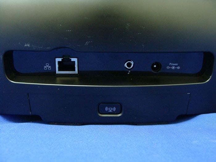
Click to zoom
Application Details
- Equipment Class
- DTS - Digital Transmission System
- Date of Grant
- Oct 06, 2011
- Application Purpose
- Original Equipment
- Date of Application
- Oct 06, 2011
- Equipment Note
- AIR SPEAKER
- Frequency Range
- 2412.00000000 - 2462.00000000
- Company
- Logitech Inc
- Country
- United States
Documents & Files
Document Text
Text extracted from the exhibit documents filed with the FCC. Open a document above to read the original.
Users Manual
for iPad, iPhone, iPod touch and iTunes Getting started with Première utilisation Logitech® Air Speaker Logitech® Air Speaker 2 for iPad, iPhone, iPod touch and iTunes Getting started with Première utilisation Logitech® Air Speaker Logitech® Air Speaker 3 Contents English 4 Français 9 Español 14 www.logitech.com/support 19 Logitech® Air Speaker 44 English Features 1. Status indicator Green: normal operation Orange: network or firmware issue (Refer to the Troubleshooting section for more details.) 2. Ethernet port RJ45 connector for direct connection to a network. Visit www.logitech.com/support/ airspeaker for setup instructions using an Ethernet cable 3. Wi-Fi Connect button For use with computer setup (optional) 4. Auxiliary input 3.5mm audio input for other music devices (optional) 5. AC power input 6. Mute Press to mute and unmute. 7. Volume Turn clockwise to increase volume; counterclockwise to decrease volume. 8. Power At each full power on, boot time is about 35 seconds. Thereafter, press for sleep mode; press again to begin playing music. 678 2345 1 Back Front To p Logitech® Air Speaker 5English 5 Setup AirPlay using an iOS device (preferred) 1. Connect the AC power supply and turn on the speaker. The speaker powers up in 35 seconds. 2. Press to open the device dock. Do not dock your iOS device while the speaker is powering up. 3. Make sure your iOS device is connected to the same Wi-Fi network on which you want to operate the speaker. 4. Dock your iOS device after the speaker powers up. A notification will appear on your screen. Select Yes to install the Logitech Air Speaker app. 5. Keep your iOS device docked, launch the APP, and then follow the on-screen instructions. Be ready to enter your Wi-Fi network password. When the Status indicator turns solid green, the Wi-Fi network connection is made. 2345 1 Logitech® Air Speaker 66 English Setup AirPlay using a computer (optional) 1. Connect the AC power supply and turn on the speaker. The speaker powers up in 35 seconds. Do not proceed with setup until the speaker power up cycle finishes. 2. Press and hold the Wi-Fi Connect button for more than 5 Seconds (the Status indicator will blink green) 3. On your computer find Wi-Fi network settings. Select the network called “Logitech Air Speaker Setup”. (For Help refer to your computer documentation.) 4. Launch an Internet browser. Enter http://192.168.1.12 in the address bar. A configuration page launches. 5. Follow the on-screen instructions. Be ready to select your Wi-Fi network and enter your password. When the Status indicator turns green, the Wi-Fi connection is made. Continue to step 6. Note: If the Status indicator changes to blinking orange, the speaker was unable to connect to your network. Please visit www.logitech.com/support/airspeaker for help and try again. 6. Reconnect your computer to your Wi-Fi network. Playing music The speaker plays music from only one device at a time. To switch from one wireless device to another wireless device, stop the current device before playing the new one. Playing music from a docked device automatically terminates play from a wireless device. Using the Air Speaker’s Auxiliary input terminates play from either a wireless or docked device. To resume play from a wireless or docked device, disconnect the audio cable from the Auxiliary input. AirPlay with iOS device (wireless) 1 1. Make sure Wi-Fi is turned on for your iOS device and your iOS device is connected to the same network as the Air Speaker 2. Tap the iPod app or a music app. 3. Find the AirPlay icon and tap it. 4. Choose the Air Speaker from the list of speakers. 5. Select a song or track to play it. 1 You can also dock your iOS device directly to the speaker to play music. Logitech® Air Speaker 7English 7 AirPlay with iTunes on your computer (wireless) 1. Open iTunes. Open Preferences. Select Devices tab. 2. Activate “Allow iTunes control from remote speakers.” Click “OK.” Close Preferences. 3. Find the AirPlay icon and click it. 4. Choose the Air Speaker from the list of speakers. 5. Select a song or track to play it. Auxiliary device 1. Connect audio device (e.g., MP3 player) to auxiliary input. 2. Select a song or track to play it. Troubleshooting The speaker is not working • Are you trying to play music from a wireless or docked device? Check the Auxiliary input and disconnect any device that might be connected. • Is the power cable connected? Is the speaker powered on? • Check the volume on the speaker and at the source. Is the speaker mute on? • Is the speaker, iOS device, or computer within range of your Wi-Fi network? Are they connected to the same Wi-Fi network? The power icon on the top of the speaker blinks orange when the speaker encounters a network issue. • Have you selected the “Logitech Air Speaker” as the output device? • Is your router (modem or gateway) working properly? Is there a disruption in your Internet service? • Security software and firewalls may block ports used by AirPlay to stream content. To resolve this issue, try updating or reconfiguring your firewall or security products. (Refer to your firewall or security documentation for more information.) • Does your iOS device have the latest software? Logitech® Air Speaker 88 English I don’t know my Wi-Fi network name (SSID) and password Please consult your router or ISP modem/ gateway documentation. If you need help, contact your router manufacturer or ISP (Internet service provider) if you’re using an ISP modem/gateway with a built-in wireless router. Status indicator Speaker conditionSTANDBYON Boot-up (up to 35 seconds)n/aslow blinking green Network connectingn/ablinking green Network connection OKbreathing greensolid green Network problembreathing orangeblinking orange Critical firmware problembreathing orangefast blinking orange Wi-Fi Connect n/afast blinking green Additional help If you have more questions about the Logitech Air Speaker, visit www.logitech.com/support/ airspeaker. What do you think? Ple…
Text truncated - open the document above for the full version.
Cover Letter(s)
Logitech Inc. 6505 Kaiser Drive, Fremont, CA 94555 USA TEL No: 360-817-1303 FAX No.: 360-817-1331 Attestation for FCC Declaration of Conformity FCC ID: DZLS00118 Data: Sep. 30, 2011 Please be notified that we, the undersigned, Logitech Inc. declares that the product which bears the above FCC ID is also compliant with the FCC requirements for DoC. The test report number supporting the DoC is DOCTR0001 (118476R-ITUSP02V02). Testing in regards to this report was done by QuieTek Corporation, located at 2F, No.345, Xinhu 2nd Rd., Neihu District,Taipei City 114,Taiwan,R.O.C. which has been accredited in accordance to all of the requirements of 47CFR 2.948 (d) and (e) of the FCC rules and KDB349827. Sincerely, Mark Ohnstad / Sr. Manager, Product Regulatory Compliance Logitech Inc. Tel: 360-817-1303 Fax: 360-817-1331 Email: [email protected]
Cover Letter(s)
October 27,2011 Subject: Supersede request for confidential letter and relateddocuments To Whom It May Concern, We, Logitech, Inc., has requested the supersede for theconfidentialletter in order to putexternal photo, internal photo and test set up photo into the list of the short-term confidentialdocuments under themarketingreason. We alsorequest to supersede the labellocationand label samples because they also reveal the part of the product photo. At the same time, we haveunderstoodthat the grant has been issued on October 7 th , 2011 and thedocuments werequested to be put into short term confidential documents has been seen in front ofpublicover 20 days. Please kindlyacceptour request and supersede thosedocuments. Sincerely, By: Sr. Manager, Product Regulatory ComplianceMark Ohnstand (Signature/ Title)(Print Name)
External Photos
Report No.: 118476R-RFUSP42V01 Page : 1 of 17 Attachment 2 : EUT Detailed Photographs (1) EUT Photo (2) EUT Photo Report No.: 118476R-RFUSP42V01 Page : 2 of 17 (3) EUT Photo (4) EUT Photo Report No.: 118476R-RFUSP42V01 Page : 3 of 17 (5) EUT Photo (6) EUT Photo
ID Label/Location Info
Logitech Inc. FCC ID.: DZLS00118 6505 Kaiser Drive, Fremont, CA 94555 USA.Tel : 360-817-1303 FCC ID Label The FCC ID Label will be placed on the equipment as shown in the photograph below.
ID Label/Location Info
Logitech Inc. FCC ID.: DZLS00118 6505 Kaiser Drive, Fremont, CA 94555 USA.Tel : 360-817-1303 FCC ID Label The FCC ID Label will be placed on the equipment as shown in the photograph below.
Internal Photos
Report No.: 118476R-RFUSP42V01 Page : 4 of 17 (7) EUT Photo (8) EUT Photo Report No.: 118476R-RFUSP42V01 Page : 5 of 17 (9) EUT Photo (10) EUT Photo Report No.: 118476R-RFUSP42V01 Page : 6 of 17 (11) EUT Photo (12) EUT Photo WiFi Antenna WiFi Antenna Report No.: 118476R-RFUSP42V01 Page : 7 of 17 (13) EUT Photo (14) EUT Photo Report No.: 118476R-RFUSP42V01 Page : 8 of 17 (15) EUT Photo (16) EUT Photo Report No.: 118476R-RFUSP42V01 Page : 9 of 17 (17) EUT Photo (18) EUT Photo Report No.: 118476R-RFUSP42V01 Page : 10 of 17 (19) EUT Photo (20) EUT Photo Report No.: 118476R-RFUSP42V01 Page : 11 of 17 (21) EUT Photo (22) EUT Photo Report No.: 118476R-RFUSP42V01 Page : 12 of 17 (23) EUT Photo (24) EUT Photo Report No.: 118476R-RFUSP42V01 Page : 13 of 17 (25) EUT Photo (26) EUT Photo Report No.: 118476R-RFUSP42V01 Page : 14 of 17 (27) EUT Photo (28) EUT Photo Report No.: 118476R-RFUSP42V01 Page : 15 of 17 (29) EUT Photo (30) EUT Photo Report No.: 118476R-RFUSP42V01 Page : 16 of 17 (31) EUT Photo (32) EUT Photo Report No.: 118476R-RFUSP42V01 Page : 17 of 17 (33) EUT Photo (34) EUT Photo
RF Exposure Info
Report No. 118476R-RFUSP42V01 Page: 1 of 3 RF Exposure Evaluation declaration Product Name Air Speaker Model No. S-00118 FCC ID DZLS00118 Applicant Logitech Inc. Address 6505 Kaiser Drive, Fremont, CA 94555 USA Date of Receipt Aug. 24, 2011 Date of Declaration Sep. 27, 2011 Report No. 118476R-RFUSP42V01 The declaration results relate only to the samples calculated. The declaration shall not be reproduced except in full without the written approval of QuieTek Corporation. This report must not be used to claim product endorsement by NVLAP any agency of the U.S. Government Report No. 118476R-RFUSP42V01 Page: 2 of 3 1. RF Exposure Evaluation 1.1. Limits According to FCC 1.1310: The criteria listed in the following table shall be used to evaluate the environment impact of human exposure to radio frequency (RF) radiation as specified in 1.1307(b) LIMITS FOR MAXIMUM PERMISSIBLE EXPOSURE (MPE) Frequency Range (MHz) Electric Field Strength (V/m) Magnetic Field Strength (A/m) Power Density (mW/cm 2 ) Average Time (Minutes) (A) Limits for Occupational/ Control Exposures 300-1500 -- -- F/300 6 1500-100,000 -- -- 5 6 (B) Limits for General Population/ Uncontrolled Exposures 300-1500 -- -- F/1500 6 1500-100,000 -- -- 1 30 F= Frequency in MHz Friis Formula Friis transmission formula: Pd = (Pout*G)/(4*pi*r 2 ) Where Pd = power density in mW/cm 2 Pout = output power to antenna in mW G = gain of antenna in linear scale Pi = 3.1416 R = distance between observation point and center of the radiator in cm Pd id the limit of MPE, 1 mW/cm 2 . If we know the maximum gain of the antenna and the total power input to the antenna, through the calculation, we will know the distance r where the MPE limit is reached. 1.2. Test Procedure Software provided by client enabled the EUT to transmit and receive data at lowest, middle and highest channel individually. The temperature and related humidity: 18°Cand 78% RH. Report No. 118476R-RFUSP42V01 Page: 3 of 3 1.3. Test Result of RF Exposure Evaluation Product : Air Speaker Test Item : RF Exposure Evaluation Test Site : No.3 OATS External Antenna Gain Antenna Gain: The maximum Gain measured in fully anechoic chamber is 5.21 dBi in logarithm scale. 802.11b Output Power Into Antenna & RF Exposure Evaluation Distance (5.21dBi): Channel Frequency (MHz) Output Power to Antenna (mW) Power Density at R = 20 cm (mW/cm2) 1 2412.00 105.1962 0.069459 6 2437.00 162.5549 0.107332 11 2462.00 113.2400 0.074771 802.11g Output Power Into Antenna & RF Exposure Evaluation Distance ( 5.21 dBi): Channel Frequency (MHz) Output Power to Antenna (mW) Power Density at R = 20 cm (mW/cm2) 1 2412.00 199.5262 0.131744 6 2437.00 272.8978 0.180190 11 2462.00 129.7179 0.085651 The distance r (4 th column) calculated from the Fries transmission formula is far shorter than 20 cm separation requirement.
Test Report
Report No. 118476R-RFUSP42V01 Page : 1 of 78 Test Report Product Name Air Speaker Model No S-00118 FCC ID. DZLS00118 Applicant Logitech Inc. Address 6505 Kaiser Drive, Fremont, CA 94555 USA Date of Receipt Aug. 24, 2011 Issue Date Sep. 27, 2011 Report No. 118476R-RFUSP42V01 Report Version V1.0 The test results relate only to the samples tested. The test report shall not be reproduced except in full without the written approval of QuieTek Corporation. This report must not be used to claim product endorsement by NVLAP any agency of the U.S. Government Report No. 118476R-RFUSP42V01 Page : 2 of 78 Test Report Certification Issue Date: Sep. 27, 2011 Report No.: 118476R-RFUSP42V01 Product Name Air Speaker Applicant Logitech Inc. Address 6505 Kaiser Drive, Fremont, CA 94555 USA Manufacturer DONG GUAN G-COM COMPUTER CO., LTD. Model No. S-00118 FCC ID. DZLS00118 EUT Rated Voltage AC 100-240V, 50/60Hz EUT Test Voltage AC 120V/60Hz Trade Name Logitech Applicable Standard FCC CFR Title 47 Part 15 Subpart C: 2010 ANSI C63.4: 2009 Test Result Complied The test results relate only to the samples tested. The test report shall not be reproduced except in full without the written approval of QuieTek Corporation. This report must not be used to claim product endorsement by NVLAP any agency of the U.S. Government Documented By : (Senior Adm. Specialist / Leven Huang ) Tested By : (Assistant Engineer / Jack Hsu ) Approved By : ( Manager / Vincent Lin ) Accredited by NIST (NVLAP) NVLAP Lab Code: 200533-0 Report No. 118476R-RFUSP42V01 Page : 3 of 78 TABLE OF CONTENTS Description Page 1. GENERAL INFORMATION .....................................................................................................5 1.1. EUT Description............................................................................................................................5 1.2. Operational Description ................................................................................................................7 1.3. Tested System Details....................................................................................................................8 1.4. Configuration of Tested System ....................................................................................................8 1.5. EUT Exercise Software .................................................................................................................8 1.6. Test Facility ...................................................................................................................................9 2. Conducted Emission..................................................................................................................10 2.1. Test Equipment............................................................................................................................10 2.2. Test Setup ....................................................................................................................................10 2.3. Limits ..........................................................................................................................................11 2.4. Test Procedure .............................................................................................................................11 2.5. Uncertainty ..................................................................................................................................11 2.6. Test Result of Conducted Emission.............................................................................................12 3. Peak Power Output ...................................................................................................................14 3.1. Test Equipment............................................................................................................................14 3.2. Test Setup ....................................................................................................................................14 3.3. Limits ..........................................................................................................................................14 3.4. Test Procedure .............................................................................................................................14 3.5. Uncertainty ..................................................................................................................................14 3.6. Test Result of Peak Power Output...............................................................................................15 4. Radiated Emission .....................................................................................................................17 4.1. Test Equipment............................................................................................................................17 4.2. Test Setup ....................................................................................................................................18 4.3. Limits ..........................................................................................................................................19 4.4. Test Procedure .............................................................................................................................20 4.5. Uncertainty ..................................................................................................................................20 4.6. Test Result of Radiated Emission................................................................................................21 5. RF antenna conducted test........................................................................................................29 5.1. Test Equipment............................................................................................................................29 5.2. Test Setup .........................................................…
Text truncated - open the document above for the full version.
Test Setup Photos
Report No.: 118476R-RFUSP42V01 Page : 1 of 3 Attachment 1: EUT Test Setup Photographs Front View of Conducted Test Back View of Conducted Test Report No.: 118476R-RFUSP42V01 Page : 2 of 3 Front View of Radiated Test Back View of Radiated Test Report No.: 118476R-RFUSP42V01 Page : 3 of 3 Front View of Radiated Test (Horn) Back View of Radiated Test (Horn)
Contact Information
Applicant
Paul Zahra(Regulatory Compliance Manager)
Test Firm
DEKRA TESTING AND CERTIFICATION CO., LTD. LinKouMirenda Liao
Technical Specifications
| # | Rule Parts | Frequency Range | Power Output |
|---|---|---|---|
| 1 | 15C | 2.41 GHz - 2.46 GHz | 273.00 mW |
Other Applications from Logitech Inc

DZLA00032
Aug 07, 2011Nano Receiver
Equipment Class
DSS - Part 15 Spread Spectrum Transmitter
DZLA00031
Jul 24, 2011Wireless Headset H600
Equipment Class
DSS - Part 15 Spread Spectrum Transmitter
DZLS00114
Jul 20, 2011Wireless module
Equipment Class
DSS - Part 15 Spread Spectrum Transmitter
DZLA00033
Jul 18, 2011Wireless Headset H800
Equipment Class
DSS - Part 15 Spread Spectrum Transmitter
DZLS00112
Jul 12, 2011S-00112
Equipment Class
DTS - Digital Transmission System