DZLA0363BA-0363B
Logitech Inc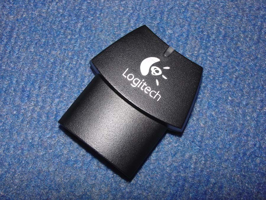
Click to zoom
Application Details
- Equipment Class
- DTS - Digital Transmission System
- Date of Grant
- Nov 22, 2004
- Application Purpose
- Original Equipment
- Date of Application
- Nov 22, 2004
- Equipment Note
- A-0363B
- Frequency Range
- 2402.00000000 - 2480.00000000
- Company
- Logitech Inc
- Country
- United States
Documents & Files
Document Text
Text extracted from the exhibit documents filed with the FCC. Open a document above to read the original.
Users Manual
1. Make sure the headset is charged and turned off. 2. Plug the headset communicator into your Xbox® controller. 3. Turn on your Xbox®. 4. Turn on your headset. 5. If your headset LED is blinking green, your headset is linked and ready for use. 6. If your headset loses the link to your Xbox® communicator, you will hear a disconnect warning tone and the headset LED will flash green continuously. 7. To re-establish the link between headset and communicator, press multi-function button and volume up simultaneously. Headset LED will blink green every 3 seconds once link is re-established. 1. Assurez-vous que le casque est chargé et éteint. 2. Branchez le Communicateur à la Xbox®. 3. Mettez la console Xbox® sous tension. 4. Mettez le casque sous tension. 5. Si le voyant du casque clignote en vert, le casque est connecté et prêt à l'emploi. 6. Si le casque perd la connexion au Communicateur Xbox®, vous entendez une tonalité d'avertissement de déconnexion et le témoin du casque clignote en vert continuellement. 7. Pour rétablir la liaison entre le casque et le Communicateur, appuyez simultanément sur le bouton multifonction et sur le bouton de hausse du volume. Une fois la connexion rétablie, le témoin du casque clignote en vert toutes les trois secondes. 1. El casco telefónico debe estar cargado y apagado. 2. Conecte el comunicador del casco telefónico al controlador Xbox ®. 3. Encienda el controlador Xbox®. 4. Encienda el casco telefónico. 5. Si el diodo del casco telefónico emite destellos verdes, indica que el casco telefónico está emparejado y listo para usar. 6. Si el casco telefónico se desempareja del comunicador Xbox®, sonará un tono de advertencia de desconexión y el diodo del casco emitirá destellos verdes. 7. Para volver a emparejar el casco y el comunicador, pulse simultáneamente los botones de varias funciones y aumento de volumen. Cuando los dispositivos vuelvan a estar emparejados, el diodo emitirá un destello verde cada 3 segundos. Technical Specifications: • Full duplex communication • Rechargeable lithium-ion battery • Range: up to 30 feet • Talk time: up to 7 hours • Weight: < 1 ounce Caractéristiques techniques: • Communication duplex intégrale • Batterie lithium ion rechargeable • Portée: jusqu’à 9 mètres • Autonomie en communication: 7 heures maximum • Poids: inférieur à 28,4 g Especificaciones técnicas: • Comunicación con dúplex completo • Pila recargable de ion litio • Radio de acción: hasta 9 metros • Tiempo en conversación: hasta 7 horas • Peso: < 28,4 g Headset Overview Présentation du casque Introducción Linking to your Xbox ® Connexion à la Xbox® Emparejamiento con Xbox® Logitech® Cordless Headset for Xbox® Quick Start Guide Casque Sans Fil Pour Xbox® Guide de démarrage rapide Functionality & Specs Fonctionnalité et caractéristiques Funciones y especificaciones 3 4 1 A C 1. When the headset battery level is low, the LED will flash red and you will hear a warning tone every few seconds. 2. Turn off the headset and connect the power adapter. 3. Plug the power adapter into an electrical outlet. 4. The charging LED will be orange when charging. If the LED does not light, the connection is not sufficient. 5. When the charging LED turns off, your headset is fully charged. Charging can take up to 1.5 hours. 1. Lorsque le niveau de charge du casque est faible, le témoin clignote en rouge. Vous entendez également une tonalité d'avertissement, qui se répète à quelques secondes d'intervalle. 2. Mettez le casque hors tension et branchez l'adaptateur secteur sur le casque. 3. Branchez l'adaptateur secteur dans la prise électrique. 4. Le témoin est de couleur orange lorsque le chargement est en cours. Si la connexion est mauvaise, le témoin ne s’allume pas. 5. Lorsque le témoin de chargement s'éteint, le casque est entièrement chargé. Le premier chargement dure environ une heure et demie. 1. Cuando el nivel de la pila sea bajo, el diodo emitirá destellos rojos y sonará un tono de advertencia cada pocos segundos. 2. Apague el casco telefónico y conecte el adaptador de alimentación. 3. Conecte el adaptador de alimentación a una toma de corriente. 4. La luz naranja constante del diodo de carga indica que el procedimiento de carga se está realizando. Si el diodo no se ilumina, se debe a que la conexión es insuficiente. 5. Una vez completada la carga, el diodo se apaga. El proceso de carga puede tardar hasta 1,5 horas. Charging the Headset Chargement du casque Carga del casco telefónico A. LED indicator B. Volume down (-) C. Volume up (+) D. Multi-function button: Power on/off, mute E. Charging LED F. Charger connection G. Ear Clip Turning the headset on and off: Push and hold the multi-function button for 3 seconds. The headset will automatically link to the Communicator. If the LED blinks green, your headset is linked and ready for use. When the headset is on, the green LED will blink every 3 seconds. Adjusting headset volume: Push volume up to raise it, or volume down to lower it. To mute your voice: Push the multi-function button (Do not hold). To disengage the mute, push the multi-function button. B D G www.logitech.com Quick Start Guide Guide de démarrage rapide © 2004 Logitech. Reservados todos los derechos. Logitech, el logotipo de Logitech y las demás marcas de Logitech pertenecen a Logitech y pueden estar registradas. Las demás marcas comerciales pertenecen a sus respectivos propietarios. ©2004 Logitech. Tous droits réservés. Logitech, le logo Logitech et les autres marques Logitech sont la propriété exclusive de Logitech et sont susceptibles d'être des marques déposées. Toutes les autres marques de commerce sont la propriété exclusive de leurs détenteurs respectifs. ©2004 Logitech. All rights reserved. Logitech, the Logitech logo, and other Logitech marks are owned by Logitech and may be registered. All other trademarks are the property of their respective owners. E 2 A. Témoin lumineux B. Volume (-) C. Volume (+) D. Bouton multifonction: marche/arrêt, coupure du son E. Té…
Text truncated - open the document above for the full version.
Cover Letter(s)
October 19, 2004 Federal Communications Commission Authorization and Evaluation Division 7435 Oakland Mills Road Columbia, Maryland 21046 To whom it may concern, We, the undersigned, hereby authorize Northwest EMC, Inc., to act on our behalf, as our agent, in the following matters related to the FCC approval of our products: report submittal, related correspondence, the signing of all documents relating to these matters, and any other lawful activity necessary to obtain such certification. Any act carried out by Northwest EMC, Inc. within the scope of this authorization shall have the same affect as our own. This authorization shall expire 12 months from original date. Sincerely, Mitchell Phillipi Sr. Compliance Engineer
Cover Letter(s)
Northwest EMC TCB Compliance Opinion Rev. 9/15/03 LABT0110 Information about the Applicant Company Name Logitech, Inc. Grantee Mitchell A. Phillipi Address 1499 SE Tech Center Place Suite 350 City, State, Zip Vancouver, WA 98683 Job Number LABT0110 Model A-0363B Dongle FCC ID DZLA0363B Agent Northwest EMC Approval Type Original Equipment Class DTS Digital Transmission System Rule Part 15.247 (15C) Overview The head mounted transceiver is a low power, battery powered, cordless transceiver which is designed to be worn over the ear of the user to enable a cordless two-way transmission with the Logitech A-0363B dongle. Recommendation All items have been resolved and completed to my satisfaction; therefore I recommend this application for approval. Signature 11/22/2004 Dave Tolman, TCB Committee Northwest EMC TCB Compliance Opinion Rev. 9/15/03 LABT0110 Findings Opinions Specification Requirements Description 47 Cfr 2.1033(b)(3) Installation guide, operating instructions,user manual Opinion The device meets the requirements of the rule. Discussion The client has provided the necessary exhibit. Reference User Manual.pdf Specification Requirements Description 47 Cfr 2.1033(b)(4) Operational description Opinion The device meets the requirements of the rule. Discussion The client has provided the necessary exhibit. Reference Operational Description.pdf Specification Requirements Description 47 Cfr 2.1033(b)(5) Frequency block diagram Opinion The device meets the requirements of the rule. Discussion The client has provided the necessary exhibit. Reference Block Diagram.pdf Specification Requirements Description 47 Cfr 2.1033(b)(5) Schematic diagram Opinion The device meets the requirements of the rule. Discussion The client has provided the necessary exhibit. Reference Schematics.pdf Specification Requirements Description 47 Cfr 2.1033(b)(7) Internal and external photos Opinion The device meets the requirements of the rule. Discussion The client has provided the necessary exhibit. Reference Internal Photos.pdf, External Photos.pdf Specification Requirements Description 47 Cfr 2.1033(b)(6) Conversions showing how the test results were achieved Opinion The device meets the requirements of the rule. Discussion The client has provided the necessary exhibit. Reference LABT0109_Report.pdf Northwest EMC TCB Compliance Opinion Rev. 9/15/03 LABT0110 Specification Requirements Description Required Exhibit Test Setup Photo Exhibit Opinion The device meets the requirements of the rule. Discussion The client has provided the necessary exhibit. Reference LABT0109_Report.pdf Specification Requirements Description 47 Cfr 1.1307(b),2.1091,2.1093 RF Exposure Hazzard Opinion The device meets the requirements of the rule. Discussion The client has provided the necessary exhibit. Reference LABT0109_Report.pdf Specification Requirements Description 47 Cfr 15.19 Labeling Opinion The device meets the requirements of the rule. Discussion The client has provided the necessary exhibit. Reference User Manual.pdf, Label.pdf Specification Requirements Description 47 Cfr 15.21 Information for user Opinion The device meets the requirements of the rule. Discussion The client has provided the necessary exhibit. Reference User Manual.pdf Specification Requirements Description 47 Cfr 15.27 Special accessories Opinion The device meets the requirements of the rule. Discussion The client has provided the necessary exhibit. The device was tested with all approved accessories. Reference LABT0109_Report.pdf Specification Requirements Description 47 Cfr 15.33 Frequency range of tests Opinion The device meets the requirements of the rule. Discussion The client has provided the necessary exhibit. Reference LABT0109_Report.pdf Specification Requirements Description 47 Cfr 15.35 Measurement detectors Opinion The device meets the requirements of the rule. Discussion The client has provided the necessary exhibit. Reference LABT0109_Report.pdf Northwest EMC TCB Compliance Opinion Rev. 9/15/03 LABT0110 Specification Requirements Description ANSI C63.4 EUT Ports All EUT ports populated,emissions maximized,Antenna height adjusted Opinion The device meets the requirements of the rule. Discussion The client has provided the necessary exhibit. Reference LABT0109_Report.pdf Specification Requirements Description 47 Cfr 15.203 Antenna Requirements Opinion The device meets the requirements of the rule. Discussion The client has provided the necessary exhibit. Reference Antenna Info.pdf Specification Requirements Description 47 Cfr 15.205 Restricted bands Opinion The device meets the requirements of the rule. Discussion The client has provided the necessary exhibit. Reference LABT0109_Report.pdf Specification Requirements Description 47 Cfr 15.207 Power line Conducted emissions Opinion The device meets the requirements of the rule. Discussion The client has provided the necessary exhibit. Reference LABT0109_Report.pdf Specification Requirements Description 47 Cfr 15.209 Spurious Emissions Opinion The device meets the requirements of the rule. Discussion The client has provided the necessary exhibit. Reference LABT0109_Report.pdf Specification Requirements Description 47 Cfr 15.247(a) Occupied Bandwidth Opinion The device meets the requirements of the rule. Discussion The client has provided the necessary exhibit. Reference LABT0109_Report.pdf Specification Requirements Description 47 Cfr 15.247(b) Output Power Opinion The device meets the requirements of the rule. Discussion The client has provided the necessary exhibit. Reference LABT0109_Report.pdf Northwest EMC TCB Compliance Opinion Rev. 9/15/03 LABT0110 Specification Requirements Description 47 Cfr 14.247(c) Band Edge Compliance Opinion The device meets the requirements of the rule. Discussion The client has provided the necessary exhibit. Reference LABT0109_Report.pdf Specification Requirements Description 47 Cfr 14.247(c) Spurious Conducted Emissions Opinion The device meets the requirements of the …
Text truncated - open the document above for the full version.
Cover Letter(s)
October 19, 2004 FCC Authorization and Evaluation Division 7434 Oakland Mills Road Columbia, MD 21046 Subject: Cover Letter To Whom It May Concern: Logitech is requesting an original certification for our unlicensed Bluetoot h Cordless Headset and Dongle (A-0363A and A- 0363B). The Logitech Bluetooth Cordless Headset and Dongle will operate under FCC Part 15.247 and consists of a head mounted, over the ear type transceiver, as well as a cordless transceiver designed to plug into a Microsoft X-Box gaming controller. The head mounted transceiver is a low power, battery powered, cordless transceiver which is designed to be worn over the ear of the user to enable a two-way transmission with the Dongle. Logitech’s Bluetooth Cordless headset and dongle will be utilizing the frequency range of 2402MHz – 2480MHz and employing a GFSK/FHSS modulation scheme. If further clarification of Logitech’s PAN is needed, please feel free to contact me at (360) 944-3708, via e-mail at [email protected] , or fax (360) 896-2020. Sincerely, Mitchell A. Phillipi Sr. Compliance Engineer Logitech, Inc.
Cover Letter(s)
October 19, 2004 Federal Communications Commission Authorization and Evaluation Division 7435 Oakland Mills Road Columbia, Maryland 21046 To whom it may concern, We hereby respectfully request that under the provision of 47 CFR 0.459, the documents listed below and attached with this application for certification be provided with confidential status. • Schematics • Theory of Operation • Frequency Block Diagrams Any exhibit / information for which we have requested confidentiality, but which may not be accorded such treatment by the FCC, should be returned to us. The documents listed above contain trade secrets that are treated as confidential by us. Substantial competitive harm to us could result should they be made available to the public. Sincerely, Mitchell Phillipi Sr. Compliance Engineer
ID Label/Location Info
M/N: A-0363B FCC ID: DZLA0363B IC: 1807D-A0363B 20.50mm 21.4mm 3.00mm DIE LINES SPOT COLORS PROCESS COLORS DIE LINE - NO PRINT COLOR SPECIFICATIONS BRAND: Logitech 08.2004 PROJECT TITLE: Desmond Dongle Nameplate DETAILS: AMR / Box M 5 25 50 75 95 C 5 25 50 75 95 Y 5 25 50 75 95 K 5 25 50 75 95 MY CY CM SPECIFICATIONS / NOTES: n/a MODIFICATION DATE: September 9th, 2004' THIS PRINT SIZE / SCALE: 100% of original Designer: Sam Lee Location: Vancouver, WA
Operational Description
Per 15.203, the antenna is internal and permanently attached. It is not intended to be serviced by the customer and is, therefore only serviceable by Logitech, Inc. authorized personnel. The antenna is an inverted L antenna with 2.01dBi gain.
RF Exposure Info
Compliance with 47 CFR 15.247(i) “Systems operating under the provisions of this section shall be operated in a manner that ensures that the public is not exposed to radio frequency energy levels in excess of the Commission's guidelines. See § 1.1307(b)(1) of this chapter.” The EUT is a cordless transceiver which is designed to be installed in an X-Box Hand-held Game Controller which allows the user to enable a two-way transmission with a Bluetooth X-Box Headset. It can be considered a portable transmitter per 47 CFR 2.1093(b). The antenna is internal to the unit and permanently attached. The antenna is an inverted L antenna with 2.01dBi gain. The maximum peak conducted output power is 2.41 mW. The maximum peak power is 3.8 mW (EIRP) for FCC ID: DZLA0363B. The transmit frequency is 2402 to 2480 MHz, therefore the EUT does not require routine SAR evaluation per “TCB Exclusions List”, footnote 3 (dated July 17, 2002). See below: The exposure category is “General Population”. The distance is < 2.5 cm. Therefore the “Low Threshold” is 24.5 mW (EIRP) – above which routine SAR evaluation would be required. Since the maximum peak power of the EUT is 3.8 mW (EIRP), routine SAR evaluation is not required. The applicant’s Bluetooth radio, FCC ID: DZLA0363B, is compliant with the requirements of 15.247(b)(5). DZLA0363B
Test Report
Logitech, Inc. Cordless Dongle for X-Box Model A-0363B November 10, 2004 Report No. LABT0109 Rev 01 Report Prepared By www.nwemc.com 1-888-EMI-CERT © 2004 Northwest EMC, Inc 22975 NW Evergreen Parkway Suite 400 Hillsboro, Oregon 97124 Certificate of Test Issue Date: November 10, 2004 Logitech, Inc. Model: A-0363B Cordless Dongle for X-Box Emissions Specification Test Method Pass Fail FCC 15.207 AC Powerline Conducted Emissions:2004 ANSI C63.4:2003 FCC 15.247(a) Occupied Bandwidth: 2004 ANSI C63.4:2003 FCC 15.247(b) Output Power: 2004 ANSI C63.4:2003 FCC 15.247(d) Band Edge Compliance: 2004 ANSI C63.4:2003 FCC 15.247(d) Spurious Conducted Emissions: 2004 ANSI C63.4:2003 FCC 15.247(d) Spurious Radiated Emissions: 2004 ANSI C63.4:2003 FCC 15.247(e) Power Spectral Density: 2004 ANSI C63.4:2003 Modifications made to the product See the Modifications section of this report Test Facility The measurement facility used to collect the data is located at: Northwest EMC, Inc. 22975 NW Evergreen Parkway, Suite 400; Hillsboro, OR 97124 Phone: (503) 844-4066 Fax: 844-3826 This site has been fully described in a report filed with and accepted by the FCC (Federal Communications Commission) and Industry Canada. Approved By: Greg Kiemel, Director of Engineering This report must not be used to claim product certification, approval, or endorsement by NVLAP, NIST, or any agency of the federal government of the United States of America. Product compliance is the responsibility of the client, therefore the tests and equipment modes of operation represented in this report were agreed upon by the client, prior to testing. This Report may only be duplicated in its entirety. The results of this test pertain only to the sample(s) tested, the specific description is noted in each of the individual sections of the test report supporting this certificate of test. Northwest EMC Revision History Revision 05/05/03 Revision Number Description Date Page Number 01 Changed EUT Model number per client request 11/23/04 Entire report Northwest EMC Accreditations and Authorizations Revision 04/01/04 FCC: Accredited by NVLAP for performance of FCC radio, digital, and ISM device testing. Our Open Area Test Sites, certification chambers, and conducted measurement facilities, have been fully described in reports filed with the FCC and accepted by the FCC in letters maintained in our files. Northwest EMC has been accredited by ANSI to ISO / IEC Guide 65 as a product certifier. We have been designated by the FCC as a Telecommunications Certification Body (TCB). This allows Northwest EMC to certify transmitters to FCC specifications in accordance with 47 CFR 2.960 and 2.962. NVLAP: Northwest EMC, Inc. is recognized under the United States Department of Commerce, National Institute of Standards and Technology, National Voluntary Laboratory Accreditation Program for satisfactory compliance with the requirements of ISO/IEC 17025 for Testing Laboratories. The NVLAP accreditation encompasses Electromagnetic Compatibility Testing in accordance with the European Union EMC Directive 89/336/EEC, ANSI C63.4, MIL-STD 461E, DO-160D and SAE J1113. Additionally, Northwest EMC is accredited by NVLAP to perform radio testing in accordance with the European Union R&TTE Directive 1999/5/EEC, the requirements of FCC, and the RSS radio standards for Industry Canada. Accreditation has been granted to Northwest EMC, Inc. under Certificate Numbers: 200629-0, 200630-0, and 200676-0. Industry Canada: Accredited by NVLAP for performance of Industry Canada RSS and ICES testing. Our Open Area Test Sites and certification chambers comply with RSS 212, Issue 1 (Provisional) and have been filed with Industry Canada and accepted. Northwest EMC has been accredited by ANSI to ISO / IEC Guide 65 as a product certifier. We have been designated by NIST and recognized by Industry Canada as a Certification Body (CB) per the APEC Mutual Recognition Arrangement (MRA). This allows Northwest EMC to certify transmitters to Industry Canada technical requirements. CAB: Designated by NIST and validated by the European Commission as a Conformity Assessment Body (CAB) to conduct tests and approve products to the EMC directive and transmitters to the R&TTE directive, as described in the U.S. - EU Mutual Recognition Agreement TÜV Product Service: Included in TUV Product Service Group's Listing of Recognized Laboratories. It qualifies in connection with the TUV Certification after Recognition of Agent's Testing Program for the product categories and/or standards shown in TUV's current Listing of CARAT Laboratories available from TUV. A certificate was issued to represent that this laboratory continues to meet TUV's CARAT Program requirements. Certificate No. USA0401C Northwest EMC Accreditations and Authorizations Revision 04/01/04 TÜV Rheinland: Authorized to carryout EMC tests by order and under supervision of TÜV Rheinland. This authorization is based on "Conditions for EMC- Subcontractors" of November 1992. NEMKO: Assessed and accredited by NEMKO (Norwegian testing and certification body) for European emissions and immunity testing. As a result of NEMKO's laboratory assessment, they will accept test results from Northwest EMC, Inc. for product certification (Authorization No. ELA 119). Technology International: Assessed in accordance with ISO Guide 25 defining the general international requirements for the competence of calibration and testing laboratories and with ITI assessment criteria LACO196. Based upon that assessment Interference Technology International, Ltd., has granted approval for specifications implementing the EU Directive on EMC (89/336/EEC and amendments). The scope of the approval was provided on a Schedule of Assessment supplied with the certificate and is available upon request. Australia/New Zealand: The National Association of Testing Authorities (NATA), Australia has been appointed by the ACA as an accreditation body to accredit test laboratories and competent b…
Text truncated - open the document above for the full version.
Test Report
Northwest EMC Power Spectral Density Revision 10/1/03 Justification The individuals and/or the organization requesting the test provided the modes, configurations and settings available to evaluate. While scanning the radiated emissions, all of the EUT parameters listed below were investigated. This includes, but may not be limited to, antennas, tuned transmit frequency ranges, operating modes, and data rates. Channels in Specified Band Investigated: Low Mid High Operating Modes Investigated: No Hop Data Rates Investigated: Maximum Output Power Setting(s) Investigated: Maximum Power Input Settings Investigated: 120 VAC, 60 Hz. Software\Firmware Applied During Test Exercise software Unknown Version Unknown Description The system was tested using special firmware developed to test all functions of the device during the test. The firmware put the radio into a no-hop mode with a modulated carrier. Transmit channels were selectable between the lowest, a middle, and the highest channels in the operating band. EUT and Peripherals Description Manufacturer Model/Part Number Serial Number EUT - Bluetooth Dongle for Game Pad Logitech, Inc. A-0363B Dongle none Video Game System Microsoft, Inc Xbox 412407321303 Xbox Game Pad Microsoft X08-17160 047355112 Cables Cable Type Shield Length (m) Ferrite Connection 1 Connection 2 Game Pad PA 1.9 PA Xbox Game Pad Video Game System AC Power No 2.0 Yes Video Game System AC Mains PA = Cable is permanently attached to the device. Shielding and/or presence of ferrite may be unknown. Northwest EMC Power Spectral Density Revision 10/1/03 Measurement Equipment Description Manufacturer Model Identifier Last Cal Interval Spectrum Analyzer Tektronix 2784 AAO 02/26/2003 24 mo Test Description Requirement: Per 47 CFR 15.247(e), the peak power spectral density conducted from the antenna port of a direct sequence transmitter must not be greater than +8 dBm in any 3 kHz band during any time interval of continuous transmission. Configuration: The peak power spectral density measurements were measured with the EUT set to low, mid, and high transmit frequencies. The measurement was made using a direct connection between the RF output of the EUT and the spectrum analyzer. The EUT was transmitting at its maximum data rate using direct sequence modulation. Per the procedure outlined in FCC 97-114, the spectrum analyzer was used as follows: The emission peak(s) were located and zoom in on within the passband. The resolution bandwidth was set to 3 kHz, the video bandwidth was set to greater than or equal to the resolution bandwidth. The sweep speed was set equal to the span divided by 3 kHz (sweep = (SPAN/3 kHz)). For example, given a span of 1.5 MHz, the sweep should be 1.5 x 10⁶ ÷ 3 x 103 = 500 seconds. External attenuation was used and added to the reading. The following FCC procedure was used for modifying the power spectral density measurements: “If the spectrum line spacing cannot be resolved on the available spectrum analyzer, the noise density function on most modern conventional spectrum analyzers will directly measure the noise power density normalized to a 1 Hz noise power bandwidth. Add 34.8 dB for correction to 3 kHz.” Completed by: NORTHWEST2 EMC Rev BETA 01/30/01 EUT: A-0363B Work Order: Serial Number:Date: Customer: Logitech, Inc.Temperature: 70 °F Attendees: NoneTested by: Greg KiemelHumidity: 47% RH Customer Ref. No.:Power: 120VAC/60HzJob Site: EV06 TEST SPECIFICATIONS Specification: 47 CFR 15.247(e)Year: 2004Method: FCC 97-114, ANSI C63.4Year: 2003 SAMPLE CALCULATIONS Meter reading on spectrum analyzer is internally compensated for cable loss and external attenuation. Power Spectral Density per 3kHz bandwidth = Power Spectral Density per 1 Hz bandwidth + Bandwidth Correction Factor. Bandwidth Correction Factor = 10*log(3kHz/1Hz) = 34.8 dB COMMENTS EUT OPERATING MODES DEVIATIONS FROM TEST STANDARD REQUIREMENTS RESULTSAMPLITUDE PassPower Spectral Density = -5.9 dBm / 3kHz SIGNATURE Tested By: DESCRIPTION OF TEST EMISSIONS DATA SHEET Power Spectral Density - Low Channel None Modulated by PRBS at maximum data rate Maximum peak power spectral density conducted from a DSSS transmitter does not exceed 8 dBm in any 3 kHz band LABT0109 10/21//2004 NORTHWEST2 EMC Rev BETA 01/30/01 EUT: A-0363B Work Order: Serial Number:Date: Customer: Logitech, Inc.Temperature: 70 °F Attendees: NoneTested by: Greg KiemelHumidity: 47% RH Customer Ref. No.:Power: 120VAC/60HzJob Site: EV06 TEST SPECIFICATIONS Specification: 47 CFR 15.247(e)Year: 2004Method: FCC 97-114, ANSI C63.4Year: 2003 SAMPLE CALCULATIONS Meter reading on spectrum analyzer is internally compensated for cable loss and external attenuation Power Spectral Density per 3kHz bandwidth = Power Spectral Density per 1 Hz bandwidth + Bandwidth Correction Factor. Bandwidth Correction Factor = 10*log(3kHz/1Hz) = 34.8 dB COMMENTS EUT OPERATING MODES DEVIATIONS FROM TEST STANDARD REQUIREMENTS RESULTSAMPLITUDE PassPower Spectral Density = -5.6 dBm / 3kHz SIGNATURE Tested By: DESCRIPTION OF TEST EMISSIONS DATA SHEET Power Spectral Density - Mid Channel None Modulated by PRBS at maximum data rate Maximum peak power spectral density conducted from a DSSS transmitter does not exceed 8 dBm in any 3 kHz band LABT0109 10/21//2004 NORTHWEST2 EMC Rev BETA 01/30/01 EUT: A-0363B Work Order: Serial Number:Date: Customer: Logitech, Inc.Temperature: 70 °F Attendees: NoneTested by: Greg KiemelHumidity: 47% RH Customer Ref. No.:Power: 120VAC/60HzJob Site: EV06 TEST SPECIFICATIONS Specification: 47 CFR 15.247(e)Year: 2004Method: FCC 97-114, ANSI C63.4Year: 2003 SAMPLE CALCULATIONS Meter reading on spectrum analyzer is internally compensated for cable loss and external attenuation Power Spectral Density per 3kHz bandwidth = Power Spectral Density per 1 Hz bandwidth + Bandwidth Correction Factor. Bandwidth Correction Factor = 10*log(3kHz/1Hz) = 34.8 dB COMMENTS EUT OPERATING MODES DEVIATIONS FROM TEST STANDARD REQUIREMENTS RESULTSAMPLITUDE PassPower Spect…
Text truncated - open the document above for the full version.
Contact Information
Applicant
Paul Zahra(Regulatory Compliance Manager)
Technical Contact
Northwest EMC, Inc.Greg Kiemel
503-844-4066
22975 NW Evergreen Parkway · Hillsboro, Oregon · United States
Test Firm
Northwest EMC, Inc.Greg Kiemel
Technical Specifications
| # | Rule Parts | Frequency Range | Power Output |
|---|---|---|---|
| 1 | 15C | 2.40 GHz - 2.48 GHz | 2.41 mW |
Other Applications from Logitech Inc
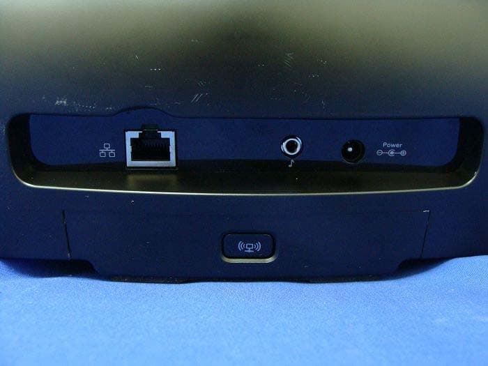
DZLS00118
Oct 06, 2011AIR SPEAKER
Equipment Class
DTS - Digital Transmission System
DZLA00032
Aug 07, 2011Nano Receiver
Equipment Class
DSS - Part 15 Spread Spectrum Transmitter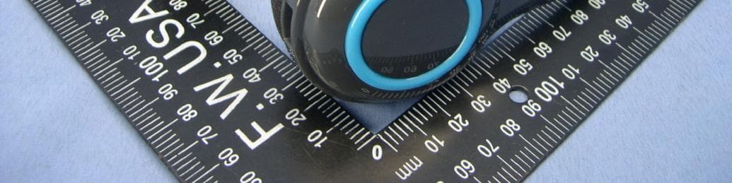
DZLA00031
Jul 24, 2011Wireless Headset H600
Equipment Class
DSS - Part 15 Spread Spectrum Transmitter
DZLS00114
Jul 20, 2011Wireless module
Equipment Class
DSS - Part 15 Spread Spectrum Transmitter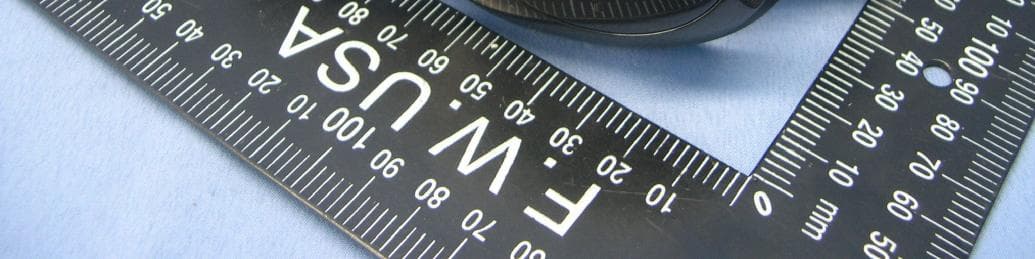
DZLA00033
Jul 18, 2011Wireless Headset H800
Equipment Class
DSS - Part 15 Spread Spectrum Transmitter