DZLF0506AF-0506A
Logitech Inc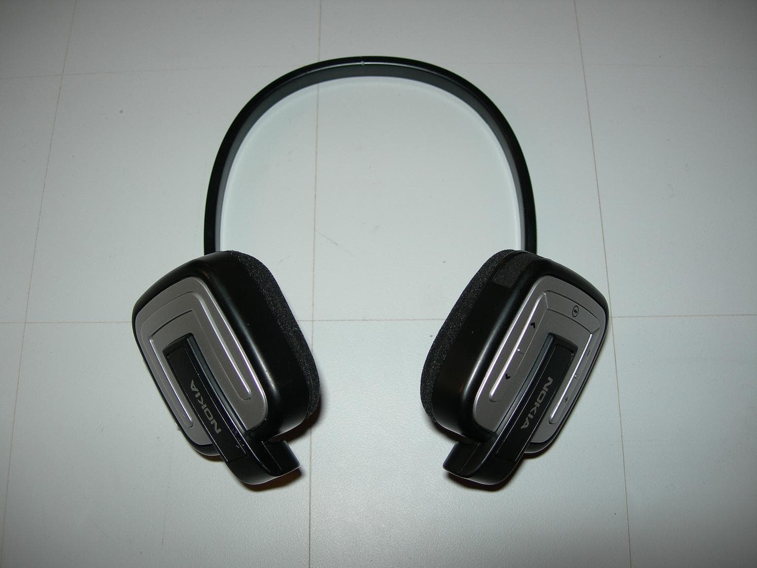
Click to zoom
Application Details
- Equipment Class
- DTS - Digital Transmission System
- Date of Grant
- Oct 24, 2006
- Application Purpose
- Original Equipment
- Date of Application
- Oct 24, 2006
- Equipment Note
- F-0506A
- Frequency Range
- 2402.00000000 - 2480.00000000
- Company
- Logitech Inc
- Country
- United States
Documents & Files
Document Text
Text extracted from the exhibit documents filed with the FCC. Open a document above to read the original.
Users Manual
User manual Manuel de l’utilisateur Logitech ® Mobile Stereo ™ HS210 Headset / Casque ® 1 English 2 English • Read these instructions. • Keep these instructions. • Heed all warnings. • Follow all instructions. • Do not use this apparatus near water. • Clean only with dry cloth. • Do not push objects into apparatus vents or slots because fire or electric shock hazards could result. • No naked (open) flame sources, such as lighted candles, should be placed on or near the apparatus. • Protect the power cord from being walked on or pinched particularly at plugs, convenience receptacles, and the point where they exit from the apparatus. • Only use attachments/accessories specified by the manufacturer. • Refer all servicing to qualified service personnel. Servicing is required when the apparatus has been damaged in any way, such as power-supply cord or plug is damaged, liquid has been spilled or objects have fallen into the apparatus, the apparatus has been exposed to rain or moisture, does not operate normally, or has been dropped. • The apparatus shall be disconnected from the mains by unplugging the power cord of the apparatus from the AC mains receptacle. • The socket-outlet shall be installed near the equipment and shall be easily accessible. WARNING: TO REDUCE THE RISK OF FIRE OR ELECTRIC SHOCK, DO NOT EXPOSE THIS APPARATUS TO RAIN OR MOISTURE. IMPORTANT SAFETY INFORMATION CAUTION ELECTRIC SHOCK HAZARD Headset Overview A. Volume controls B. Charge connector C. Multifunction button D. LED indicator (headset LED) E. WindStop ™ microphone F. Charge LED indicator G. Track controls H. Reset button Introduction Safety A F C D E B H G 3 English 4 English Check for Phone Compatibility The Logitech® Mobile Stereo™ HS210 is compatible with most Bluetooth® mobile phones. Consult your phone manufacturer for more information on compatibility. Charge Headset Battery The Logitech® Mobile Stereo™ HS210 comes with a lithium-ion rechargeable battery that must be fully charged before you use the headset for the fi rst time. 1. Turn off the headset. Connect the power adapter to the headset. Plug the AC adapter into the electrical outlet. 2. The charge LED will be green while headset is charging. If the LED is not green, check the connection. 3. When the headset is fully charged, the green LED turns off. Charging can take up to 3 hours. 4. Remove the AC adapter from the headset. 5. Your headset is now ready for pairing. See page 4, or the Quick-start Guide for details on pairing. Pairing Your Host to a Mobile Phone Using Bluetooth® Wireless Technology You must pair your headset to a mobile phone using Bluetooth® wireless technology. For more details, refer to your mobile phone user guide or contact the phone’s manufacturer. 1. Turn on your phone. Make sure the battery is charged in both devices. Turn off the headset. 2. Press and hold the Multifunction button until the headset indicator light fl ashes blue and red (about 10 seconds). 3. The headset now is in Pairing mode. Release the button. The indicator light will continue fl ashing red and blue. 4. Follow the pairing instructions for your Bluetooth® phone. Typically, this is done by going to a “setup” or “connect” menu on your phone and then selecting the options to “discover” Bluetooth® devices. 5. Your phone should fi nd the ‘Logi_HS210’ headset. Confi rm to pair. 6. Your phone should prompt you for a passkey or PIN. The PIN/passkey is: 0000. 7. If pairing was successful, the headset LED will fl ash blue. 8. If pairing fails, turn the headset and phone off and repeat the process. 9. If headset and phone are not paired within 3 minutes, the indicator light will fl ash red 3 times and the host will turn off. Wearing and Using Your Headset Pairing Your Headset Multifunction button Charge LED 5 English 6 English Using Your Logitech ® Mobile Stereo ™ HS210 Note: The features listed below are phone dependent. Check your phone user’s manual. 1. Starting a Call Dial the numbers on your mobile phone keypad. When the call is connected, your headset will automatically connect to the phone to take the call. 2. Using Voice Dialing* Press and release the Multifunction button and Volume (+) simultaneously when in standby mode. 3. Ending a Call Press and release the Multifunction button on the headset when in Call mode, or end call from mobile phone keypad. 4. Answering a Call After an incoming ring tone, press and release the Multifunction button once. Or, you can answer the call with your mobile phone’s keypad. To transfer a call to your headset, press and release the Volume (+) and Track (>) simultaneously once, or use the menu on your phone. 5. Muting a Call Press the Volume (+) and Volume (-) simultaneously for 1 second while in Call mode. You will hear a double beep the fi rst time. 6. Ending Mute Press the Volume (+) and Volume (-) simultaneously for 3 seconds while in Mute mode. You will hear a double beep. * Phone model dependent. Feature Summary The Logitech ® Mobile Stereo™ HS210 supports call reject and other advanced features. See the table below for a full summary of features supported. Standard Features How to What you doWhat you seeWhat you hear Turning On Press multi-function button (MFB) briefl y Repeating BLUE LED FlashesBrief low-to-high-tone Answering CallPress MFB briefl y3 BLUE fl ashesDouble beep Ending callPress MFB briefl y3 repeating BLUE fl ashesDouble beep Pairing Mode From Off state, press and hold MFB button for 10 seconds Alternating BLUE/RED LED fl ashes, BLUE fl ashing LED when paired No audio Standby or connected - - -Repeating BLUE FlashesNo audio Voice Dialing Press MFB and Vol(+) when in standby or connected Slow repeating BLUE fl ashesDouble beep Mic Mute-on Press and hold Vol(+) and Vol(-) button simultaneously for 1 second Slow repeating BLUE fl ashesDouble beep Ending mic mute Press and hold Vol(+) and Vol(-) button simultaneously for 1 second Slow repeating BLUE fl ashesDouble beep Low Battery - - -Repeating RED fl ashesDouble…
Text truncated - open the document above for the full version.
Cover Letter(s)
August 31, 2006 Federal Communications Commission Authorization and Evaluation Division 7435 Oakland Mills Road Columbia, Maryland 21046 To whom it may concern, We, the undersigned, hereby authorize Northwest EMC, Inc., to act on our behalf, as our agent, in the following matters related to the FCC approval of our products: report submittal, related correspondence, the signing of all documents relating to these matters, and any other lawful activity necessary to obtain such certification. Any act carried out by Northwest EMC, Inc. within the scope of this authorization shall have the same affect as our own. This authorization shall expire 12 months from original date. Sincerely, Mitchell Phillipi Sr. Compliance Engineer
Cover Letter(s)
Northwest EMC TCB Compliance Opinion Rev. 9/15/03 LABT0175 Information about the Applicant Company Name Logitech Grantee Mitchell Phillipi Address 1499 SE Tech Center Place Suite 350 City, State, Zip Vancouver, WA 98683 Job Number LABT0175 Model F-0506A FCC ID DZLF0506A Agent Northwest EMC Approval Type Original Equipment Class DTS Digital Transmission System Rule Part 15.247DSSS Industry Canada Information Model F-0506A 1807D-F0506A Rule Part RSS210 Overview Logitech is requesting an original certification for our unlicensed Stereo Headset Logitech MN: F- 0506A. The Stereo Headset will operate under FCC Part 15.247 and consists of a head mounted, over the ear type transceiver. The FCC ID for the Stereo Headset is DZLF0506A. The head mounted transceiver is a low power, battery powered, cordless transceiver which is designed to be worn over the ear of the user to enable a two-way transmission with a Bluetooth compatible cellular telephone. Recommendation All items have been resolved and completed to my satisfaction; therefore I recommend this application for approval. Signature 9/21/2006 Dave Tolman, TCB Committee
Cover Letter(s)
February 1, 2006 FCC Authorization and Evaluation Division 7434 Oakland Mills Road Columbia, MD 21046 Subject: Cover Letter To Whom It May Concern: Logitech is requesting an original certification for our unlicensed Stereo Bluetooth Headset (MN: F-0506A). The Stereo Bluetooth Headset will operate under FCC Part 15.247 and consists of a head mounted, over the ear type transceiver. The head mounted transceiver is a low power, battery powered, cordless transceiver which is designed to be worn over the ear of the user to enable a two-way transmission with a Bluetooth compatible cellular telephone. Logitech’s Stereo Bluetooth Headset will be utilizing the frequency range of 2402MHz – 2480MHz and employing a GFSK/FHSS modulation scheme. If further clarification of the Logitech Stereo Bluetooth Headset is needed, please feel free to contact me at (360) 944-3708, via e- mail at [email protected] , or fax (360) 896-2020. Sincerely, Mitchell A. Phillipi Sr. Compliance Engineer Logitech, Inc.
Cover Letter(s)
September 16, 2005 Federal Communications Commission Authorization and Evaluation Division 7435 Oakland Mills Road Columbia, Maryland 21046 To whom it may concern, We hereby respectfully request that under the provision of 47 CFR 0.459, the documents listed below and attached with this application for certification be provided with confidential status. • Schematics • Theory of Operation • Frequency Block Diagrams Any exhibit / information for which we have requested confidentiality, but which may not be accorded such treatment by the FCC, should be returned to us. The documents listed above contain trade secrets that are treated as confidential by us. Substantial competitive harm to us could result should they be made available to the public. Sincerely, Mitchell Phillipi Sr. Compliance Engineer
ID Label/Location Info
M/N: F 0506A- IC: 1807D-F0506AID FCC: DZLF0506AID MADE IN CHINA
Operational Description
Per 15.203, the antenna is internal and permanently attached. It is not intended to be serviced by the customer and is, therefore only serviceable by Logitech, Inc. authorized personnel. The antenna is a Rufa 2.4GHz SMD Antenna by gigaAnt , with 2.67dBi max peak gain once installed on the PCBA. The gigaAnt product specification sheet is included in this exhibit. Product Specification Product Specification Rufa 2.4 GHz SMD Antenna Rev : AE020157-F / April 30 2004 Rufa 2.4 GHz SMD Antenna 2 (10)Subject to changes without prior notice 1. FEATURES - Designed for 2.4 GHz applications [Bluetooth TM , WiFi TM (802.11b/g), Zigbee TM , WiMedia TM etc.] - Intended for SMD mounting - Supplied in tape on reel 2. DESCRIPTION - Mobile phones - PDAs - Headsets - Laptops - PC- Cards - CF- Cards 3. APPLICATION The Rufa antenna is intended for use with all 2.4 GHz applications. The antenna requires a groundplane, i.e your device acts as an active part of the antenna and thus demand careful consideration concerning its placement TABLE OF CONTENT 1. Features ......................................................................................................................................................................... 2 2. Description ..................................................................................................................................................................... 2 3. Application ...................................................................................................................................................................... 2 4. Model names .................................................................................................................................................................. 3 5. General data ................................................................................................................................................................... 3 6. Electrical characteristics ................................................................................................................................................. 3 7. Electrical performance .................................................................................................................................................... 4 7.1 Voltage Standing Wave Ratio ............................................................................................................................... 4 7.2 3D-Radiation ........................................................................................................................................................ 4 7.3 Radiation patterns ................................................................................................................................................ 4 8. Antenna Dimensions ....................................................................................................................................................... 5 9. Antenna Foot print .......................................................................................................................................................... 5 10. Electrical interface ........................................................................................................................................................ 6 10.1 Transmission line and matching ......................................................................................................................... 6 10.2 Test board dimensions ....................................................................................................................................... 6 10.3 Test board matching ........................................................................................................................................... 6 11. Soldering ....................................................................................................................................................................... 6 11.1 Recommended soldering conditions .................................................................................................................. 6 11.2 Leadfree soldering ............................................................................................................................................. 6 12. Reliability ...................................................................................................................................................................... 7 12.1 Temperature and Humidity ................................................................................................................................. 7 12.2 Mechanical ......................................................................................................................................................... 7 12.3 Miscellaneous .................................................................................................................................................... 7 12.4 Judgement standard .......................................................................................................................................... 7 13. Hazardous Material Reguration Conformance .............................................................................................................. 7 14. Application example ...................................................................................................................................................... 8 15. Packaging ..................................................................................................................................................................... 9 15.1 Shelf storage recommendation .......................................................................................................................... 9 15.2 Tape characteristics ..............................................................................................…
Text truncated - open the document above for the full version.
RF Exposure Info
Compliance with 47 CFR 15.247(i) “Systems operating under the provisions of this section shall be operated in a manner that ensures that the public is not exposed to radio frequency energy levels in excess of the Commission's guidelines. See § 1.1307(b)(1) of this chapter.” The EUT is a cordless Bluetooth transceiver which is designed to be worn over the ear of the user to enable a two-way transmission with a Bluetooth compatible cellular telephone. The headset is considered portable per 47 CFR 2.1093(b). The Antenna is internal to the unit and has 2.59 dB max gain. The maximum peak conducted output power is 1.86 mW. The maximum peak power is 3.38 mW (EIRP) for FCC ID: DZLF0506A. The transmit frequency is 2402 to 2480 MHz, therefore the EUT does not require routine SAR evaluation per "TCB Exclusions List", footnote 3 (dated July 17, 2002). See below: The exposure category is "General Population." The distance is < 2.5 cm. Therefore the "Low Threshold" is 24.5 mW (EIRP) -- above which routine SAR evaluation would be required. Since the maximum peak power of the EUT is 3.38 mW (peak (EIRP), routine SAR evaluation is not required. The applicant's Bluetooth radio, FCC ID: DZLF0506A, is compliant with the requirements of 15.247(i).
Test Report
Logitech, Inc. F-0506A September 21, 2005 Report No. LABT0175 Report Prepared By www.nwemc.com 1-888-EMI-CERT © 2005 Northwest EMC, Inc 22975 NW Evergreen Parkway Suite 400 Hillsboro, Oregon 97124 Certificate of Test Issue Date: September 21, 2005 Logitech, Inc. Model: F-0506A Emissions Specification Test Method Pass Fail FCC 15.207 AC Powerline Conducted Emissions:2005-04 ANSI C63.4:2003 FCC 15.247(a) Occupied Bandwidth:2005-04 ANSI C63.4:2003 FCC 15.247(b) Output Power:2005-04 ANSI C63.4:2003 FCC 15.247(d) Band Edge Compliance:2005-04 ANSI C63.4:2003 FCC 15.209(d) Spurious Radiated Emissions :2005-04 ANSI C63.4:2003 FCC 15.247(d) Spurious Conducted Emissions:2005-04 ANSI C63.4:2003 FCC 15.247(e) Power Spectral Density:2005-04 ANSI C63.4:2003 FCC 15.109(g) (CISPR 22:1997) Class B:2005-04 Radiated Emissions ANSI C63.4:2003 Modifications made to the product See the Modifications section of this report Test Facility The measurement facility used to collect the data is located at: Northwest EMC, Inc. 22975 NW Evergreen Parkway, Suite 400; Hillsboro, OR 97124 Phone: (503) 844-4066 Fax: 844-3826 This site has been fully described in a report filed with and accepted by the FCC (Federal Communications Commission) and Industry Canada. Approved By: Greg Kiemel, Director of Engineering This report must not be used to claim product certification, approval, or endorsement by NVLAP, NIST, or any agency of the federal government of the United States of America. Product compliance is the responsibility of the client, therefore the tests and equipment modes of operation represented in this report were agreed upon by the client, prior to testing. This Report may only be duplicated in its entirety. The results of this test pertain only to the sample(s) tested, the specific description is noted in each of the individual sections of the test report supporting this certificate of test. Northwest EMC Revision History Revision 05/05/03 Revision Number Description Date Page Number 00 None Northwest EMC Accreditations and Authorizations Revision 03/18/05 FCC: Accredited by NVLAP for performance of FCC radio, digital, and ISM device testing. Our Open Area Test Sites, certification chambers, and conducted measurement facilities have been fully described in reports filed with the FCC and accepted by the FCC in letters maintained in our files. Northwest EMC has been accredited by ANSI to ISO / IEC Guide 65 as a product certifier. We have been designated by the FCC as a Telecommunications Certification Body (TCB). This allows Northwest EMC to certify transmitters to FCC specifications in accordance with 47 CFR 2.960 and 2.962. NVLAP: Northwest EMC, Inc. is recognized under the United States Department of Commerce, National Institute of Standards and Technology, and National Voluntary Laboratory Accreditation Program for satisfactory compliance with the requirements of ISO/IEC 17025 for Testing Laboratories. The NVLAP accreditation encompasses Electromagnetic Compatibility Testing in accordance with the European Union EMC Directive 89/336/EEC, ANSI C63.4, MIL- STD 461E, DO-160D and SAE J1113. Additionally, Northwest EMC is accredited by NVLAP to perform radio testing in accordance with the European Union R&TTE Directive 1999/5/EEC, the requirements of FCC, and the RSS radio standards for Industry Canada. 200629-0 200630-0 200676-0 Industry Canada: Accredited by NVLAP for performance of Industry Canada RSS and ICES testing. Our Open Area Test Sites and certification chambers comply with RSS 212, Issue 1 (Provisional) and have been filed with Industry Canada and accepted. Northwest EMC has been accredited by ANSI to ISO / IEC Guide 65 as a product certifier. We have been designated by NIST and recognized by Industry Canada as a Certification Body (CB) per the APEC Mutual Recognition Arrangement (MRA). This allows Northwest EMC to certify transmitters to Industry Canada technical requirements. CAB: Designated by NIST and validated by the European Commission as a Conformity Assessment Body (CAB) to conduct tests and approve products to the EMC directive and transmitters to the R&TTE directive, as described in the U.S. - EU Mutual Recognition Agreement. TÜV Product Service: Included in TUV Product Service Group's Listing of Recognized Laboratories. It qualifies in connection with the TUV Certification after Recognition of Agent's Testing Program for the product categories and/or standards shown in TUV's current Listing of CARAT Laboratories, available from TUV. A certificate was issued to represent that this laboratory continues to meet TUV's CARAT Program requirements. Certificate No. USA0401C. TÜV Rheinland: Authorized to carryout EMC tests by order and under supervision of TÜV Rheinland. This authorization is based on "Conditions for EMC-Subcontractors" of November 1992. Northwest EMC Accreditations and Authorizations Revision 03/18/05 NEMKO: Assessed and accredited by NEMKO (Norwegian testing and certification body) for European emissions and immunity testing. As a result of NEMKO's laboratory assessment, they will accept test results from Northwest EMC, Inc. for product certification (Authorization No. ELA 119). Technology International: Assessed in accordance with ISO Guide 25 defining the general international requirements for the competence of calibration and testing laboratories and with ITI assessment criteria LACO196. Based upon that assessment, Interference Technology International, Ltd., has granted approval for specifications implementing the EU Directive on EMC (89/336/EEC and amendments). The scope of the approval was provided on a Schedule of Assessment supplied with the certificate and is available upon request. Australia/New Zealand: The National Association of Testing Authorities (NATA), Australia has been appointed by the ACA as an accreditation body to accredit test laboratories and competent bodies for EMC standards. Accredited test reports or assessments by competent bodies must carry the NATA logo.…
Text truncated - open the document above for the full version.
Contact Information
Applicant
Paul Zahra(Regulatory Compliance Manager)
Test Firm
Northwest EMC, Inc.Greg Kiemel
Technical Specifications
| # | Rule Parts | Frequency Range | Power Output |
|---|---|---|---|
| 1 | 15C | 2.40 GHz - 2.48 GHz | 1.86 mW |
Other Applications from Logitech Inc
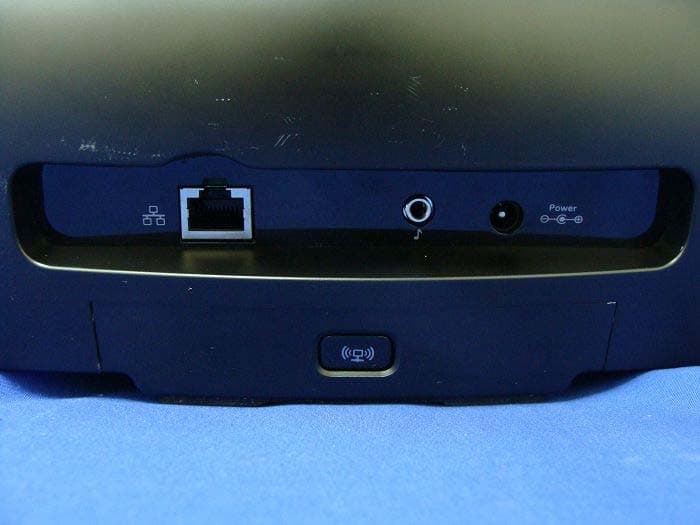
DZLS00118
Oct 06, 2011AIR SPEAKER
Equipment Class
DTS - Digital Transmission System
DZLA00032
Aug 07, 2011Nano Receiver
Equipment Class
DSS - Part 15 Spread Spectrum Transmitter
DZLA00031
Jul 24, 2011Wireless Headset H600
Equipment Class
DSS - Part 15 Spread Spectrum Transmitter
DZLS00114
Jul 20, 2011Wireless module
Equipment Class
DSS - Part 15 Spread Spectrum Transmitter
DZLA00033
Jul 18, 2011Wireless Headset H800
Equipment Class
DSS - Part 15 Spread Spectrum Transmitter