ENPESTEEM192CHPData Packet Radio
Electronic Systems Technology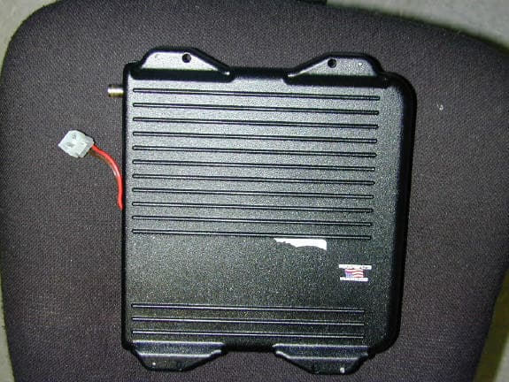
Click to zoom
Application Details
- Equipment Class
- TNB - Licensed Non-Broadcast Station Transmitter
- Date of Grant
- Sep 10, 2003
- Application Purpose
- Original Equipment
- Date of Application
- Sep 10, 2003
- Equipment Note
- Data Packet Radio
- Frequency Range
- 450.10000000 - 470.00000000
- Country
- United States
Documents & Files
Document Text
Text extracted from the exhibit documents filed with the FCC. Open a document above to read the original.
Users Manual
Revision: 2.0Date: March 26, 2001 Electronic Systems Technology (EST) copyrights this manual and the firmware described in it, with all rights reserved. Under the copyright laws, this manual or the firmware internal to the ESTeem unit may not be copied, in whole or part, without the written consent of EST. Under the law, copying includes translating into another language. EST cannot guarantee that you will receive notice of a revision to the firmware described in the manual, even if you have returned a registration/warranty card received with the product. You should periodically check with your authorized EST dealer or call factory direct. EST and the EST logo are registered trademarks of Electronic Systems Technology, Inc. Simultaneously published in the United States and Canada. All rights reserved. ESTEEM USERS MANUAL for MODELS 192C/F/M Firmware Versions 1.46 and above. March 2001 Revised: 26 Mar 01 PRODUCT WARRANTY Electronic Systems Technology, Inc., (hereinafter EST) expressly warrants its products as free of manufacturing defects for a period of one year from the date of sale to first user/customer. THERE ARE NO OTHER WARRANTIES, EXPRESS OR IMPLIED AND THERE IS EXPRESSLY EXCLUDED ALL WARRANTIES OF MERCHANTABILITY OR FITNESS FOR A PARTICULAR PURPOSE. NO OTHER WARRANTY GIVEN BY ANY EMPLOYEE, AGENT, DISTRIBUTOR OR OTHER PERSON WITH RESPECT TO THE PRODUCT SHALL BE BINDING ON EST. LIMITATION OF LIABILITY: EST's liability shall be limited to refunding of purchase price, repair or replacement of product. IN NO EVENT SHALL EST HAVE LIABILITY FOR CONSEQUENTIAL, INCIDENTAL, SPECIAL OR EXEMPLARY DAMAGES CAUSED DIRECTLY OR INDIRECTLY BY THE PRODUCT, INCLUDING BUT NOT LIMITED TO ANY INTERRUPTION OF SERVICES, LOSS OF BUSINESS OR ANTICIPATORY PROFITS. IN NO EVENT SHALL EST BE LIABLE FOR ANY DAMAGES WHATSOEVER IN EXCESS OF THE PURCHASE PRICE OF THE PRODUCT. In the event that a unit or part requires replacement or factory servicing, the following conditions apply: a) Customer must obtain from EST an authorized RMA (Return Materials Authorization) number (call 509-735-9092 Customer Support) before shipment of product or parts to EST for any reason; b) If the whole unit is shipped, it must be in its original carton and shipping components, or a carton and shipping components supplied by EST, or if parts only are shipped, they must be packaged and cushioned so as to prevent damage in transit and shipped freight prepaid; PRODUCT WILL BE CONSIDERED OUT OF WARRANTY IF: a) If the product is damaged due to improper or abnormal use, abuse, mishandling, accident or improper maintenance or failure to follow operating instruction; b) If the product is defective as a result of sand, dirt, or water damage; c)If any factory-sealed enclosure has been opened or shows evidence of an attempt to be opened; d) If defects or damage are caused by the use of unauthorized parts or unauthorized service; e)If the product has had its serial numbers altered or removed. Warranty repair form must be accompanied by proof of user's purchase of unit. Product must be shipped to the manufacturer at the following address: Electronic Systems Technology 415 North Quay Street Kennewick, Washington USA 99336 ADDITIONAL SERVICE: If EST releases an improvement update to firmware internal to the ESTeem unit during the 90 day period after the unit was purchased by the first user/customer, EST will update the applicable unit with the revised version at no charge other than for UPS handling and shipping to and from your location to the EST factory. Return of any such item must be accompanied with proof of purchase. TABLE OF CONTENTS Revised: 26 Mar 01 CHAPTER 1 - STARTING OUT Before You Start.................................................. 1-2 ESTeem Utility.................................................... 1-2 Installing ESTeem Utility Software...................... 1-2 Running The Program ......................................... 1-2 Starting Out......................................................... 1-3 Basic ESTeem Programming ............................... 1-5 Help Functions .................................................... 1-5 Saving a Program ................................................ 1-6 Restoring Factory Defaults................................... 1-6 CHAPTER 2 - MODES OF OPERATION Command Mode .................................................. 2-2 Converse Mode.................................................... 2-2 Transparent Mode ............................................... 2-3 Semi-Transparent Mode ...................................... 2-3 Hardware Mode Control ...................................... 2-3 CHAPTER 3 - PROGRAMMING ESTEEM FEATURES Digi-Repeating Feature........................................ 3-2 Global Broadcast Feature..................................... 3-2 Auto Transmit Feature......................................... 3-3 Auto Connect Feature .......................................... 3-3 Multi-Connect Feature......................................... 3-3 Remote Programming Feature ............................. 3-4 Security Feature.................................................. .3-4 Hardware Ring Line.............................................3-5 Packet Monitor Feature ........................................3-5 Using The Infrared Communications Port ............3-5 Updating Flash Memory.......................................3-6 CHAPTER 4 - ESTEEM APPLICATION PROGRAMS Transparent Auto-Connect ...................................4-2 Transparent Auto-Connect Global........................4-2 Interactive Terminal Applications ........................4-3 Programmable Logic Controllers..........................4-3 CHAPTER 5 - RS-232C/422/485 INTERFACING DTE vs DCE........................................................5-2 Flow Control........................................................5-2 Memory Buffers ...................................................5-3 Data Terminal Ready .............…
Text truncated - open the document above for the full version.
Cover Letter(s)
ELECTRONIC SYSTEMS TECHNOLOGY, INC. 415 North Quay St. • Kennewick, WA 99336 • Phone (509) 735-9092 • Fax (509) 783-5475 September 10, 2003 Federal Communications Commission 7435 Oakland Mills Road Columbia, MD 21046 To Whom It May Concern, 0.459 Request that materials or information submitted to the Commission be withheld from public inspection. The information included in this filing contains innovative new design specifications for the new ESTeem 192CHP product. We have spent considerable time researching and developing this product to out perform our competitors and request for the Schematics, Parts List and Block Diagram not be released to the public. Sincerely, D. Brent Strecker Engineer Cc: dbs/lb
External Photos
Bottom Top
ID Label/Location Info
Label Location ELECTRONIC SYSTEMS TECHNOLOGY, INC. Kennewick, Washington • U.S.A. www.esteem.com ESTeem Tested To Comply With FCC Standards Model 192CHP RS-232C/422/485 SETUP SWITCH TABLE BIT 1 OFF Default baud rate 19.2K, N, 8,1 BIT 1 ON Use software to select baud rate BIT 2 OFF Enter Command Mode upon initialization BIT 2 ONEnter Conversation Mode upon initialization FCC ID: ENPESTEEM192CHP CANADA ?????? MADE IN USA Restoring Factory Defaults 1. Set Bit 1 & 2 OFF 2. Reset ESTeem 3. Type FA Printed on 2 in. X 5 in. Label Shown by dotted line
Internal Photos
PCB Top PCB Bottom Chassis Shells
Operational Description
192 C Description of device and circuitry for Determining and stabilizing operating frequency The ESTeem 192 utilizes 2 VCO’s for the transmitter. The local oscillator (540 to 560 MHz) consists of a synthesized VCO locked to a 9.6 Mhz TCXO. The Exciter 90 MHz VCO uses a 12MHz TCXO. Each VCO uses a low pass filter and is independently shielded. The loop bandwidth of each VCO is optimized for frequency stability and low susceptibility to microphonics. See overall transceiver block diagram. The transmitter power up circuit consist of 3 stages. The first stage starts the Exciter VCO. Stage two turns on stages 1 and 2 of the power amp, while allowing time for the Exciter VCO to stabilize. Stage three turns on stages 3 and 4 of the power amp, and ramps the final section of the power amplifier on. Upon turn off the stages are delayed from each other in the reverse order. This power up sequence provides a clean stable turn on and off sequence of the transmitter. Suppression of Spurious Radiation Modulation and Power Limiting Spurious Radiation Suppression The transmit signal is passed through 2, three pole band pass filters before amplified by the power amp. The power amp output is fed to a 2 pole filter for harmonic attenuation and suppression of spurious emissions. Modulation Modulation is supplied by a 4 level FSK modem data pump. The signal is passed through a RC low pass filter. Then through a 3 pole low pass Gaussian pre-mod filter with a cut off of 6.8 kHz, 18db per octave. Note: Primary bandwidth control is by the data pump. Clock spurs and quantization are filtered in the Gaussian pre-mod filter. The signal is modulated using a VCXO with a maximum worst case mod of 5 kHz. Power Limiting The RF power output is limited by regulator U707 which supplies 8 VDC to stages 1 and 2 of the power amp U702. The power amp U702 is also limited in design.
Parts List/Tune Up Info
ELECTRONIC SYSTEMS TECHNOLOGY, INC. 415 North Quay St. • Kennewick, WA 99336 • Phone (509) 735-9092 • Fax (509) 783-5475 September 10, 2003 Federal Communications Commission 7435 Oakland Mills Road Columbia, MD 21046 To Whom It May Concern, The 192CHP is tuned during factory production and requires no additional tuning by the installer or end user. Sincerely, D. Brent Strecker Engineer Cc: dbs/lb
RF Exposure Info
RF Exposure FCC ID.: ENPESTEEM192CHP RF exposure requirements for this device are dealt with at the time of licensing. The radio transmits short data bursts.
Test Report
Nemko Test Report: 3L0216RUS1 Applicant: Electronic Systems Technology 415 N. Quay St. Suit 4 Kennewick, WA 99336 Equipment Under Test: 192CHP (E.U.T.) Narrow Band Packet Burst Wireless Modem In Accordance With: FCC Part 90, Subpart I Private Land Mobile Transmitter Tested By: Nemko USA Inc. 802 N. Kealy Lewisville, TX 75057-3136 Authorized By: Tom Tidwell, Frontline Manager Date: 9/3/03 Total Number of Pages: 43 Nemko USA Inc. FCC PART 90, SUBPART I PRIVATE LAND MOBILE TRANSMITTER EQUIPMENT: 190CHP PROJECT NO.: 3L0216R Page 2 of 43 Table of Contents Section 1. Summary of Test Results.......................................................................... 3 Section 1. Summary of Test Results.......................................................................... 3 Section 2. General Equipment Specification.............................................................. 5 Section 3. RF Power Output ...................................................................................... 7 Section 4. Modulation Characteristics........................................................................ 8 Section 5. Occupied Bandwidth................................................................................. 9 Section 6. Spurious Emissions at Antenna Terminals ............................................. 14 Section 7. Field Strength of Spurious Emissions..................................................... 23 Section 8. Frequency Stability................................................................................. 27 Section 9. Transient Frequency Behavior ................................................................ 29 Section 10. Test Equipment List ................................................................................ 32 ANNEX A - TEST METHODOLOGIES.......................................................................... 33 ANNEX B - TEST DIAGRAMS ...................................................................................... 39 Nemko USA Inc. FCC PART 90, SUBPART I PRIVATE LAND MOBILE TRANSMITTER EQUIPMENT: 190CHP PROJECT NO.: 3L0216R Page 3 of 43 Section 1. Summary of Test Results Manufacturer: Electronic Systems Technology Model No.: 192CHP Serial No.: CHP 12040 General: All measurements are traceable to national standards. These tests were conducted on a sample of the equipment for the purpose of demonstrating compliance with FCC Part 90, Subpart I. New Submission Production Unit Class II Permissive Change Pre-Production Unit THIS TEST REPORT RELATES ONLY TO THE ITEM(S) TESTED. THE FOLLOWING DEVIATIONS FROM, ADDITIONS TO, OR EXCLUSIONS FROM THE TEST SPECIFICATIONS HAVE BEEN MADE. See “ Summary of Test Data”. TESTED BY: ___Eldon Berry________________ DATE: ___August 28, 2003___ Nemko USA, Inc. authorizes the above named company to reproduce this report provided it is reproduced in its entirety and for use by the company’s employees only. Any use which a third party makes of this report, or any reliance on or decisions to be made based on it, are the responsibility of such third parties. Nemko USA, Inc. accepts no responsibility for damages, if any, suffered by any third party as a result of decisions made or actions based on this report. This report applies only to the items tested. Nemko USA Inc. FCC PART 90, SUBPART I PRIVATE LAND MOBILE TRANSMITTER EQUIPMENT: 190CHP PROJECT NO.: 3L0216R Page 4 of 43 Summary Of Test Data NAME OF TEST PARA. NO. SPEC. MEAS. RESULT RF Power Output 90.205 10W/30W Complies Audio Frequency Response TIA EIA- 603.3.2.6 N/A N/A N/A Audio Low-Pass Filter Response TIA EIA- 603.3.2.6 N/A N/A N/A Modulation Limiting TIA EIA- 603.3.2.6 N/A 2.5kHz/ 3.5 kHz Complies Occupied Bandwidth 90.210 Mask C or D Plots Complies Spurious Emissions at Antenna Terminals 90.210 Mask C or D Plots Complies Field Strength of Spurious Emissions 90.210 Mask C or D Table Complies Frequency Stability 90.213 5 ppm 1.74 ppm Complies Transient Frequency Behavior 90.214 Plot Plots Complies Footnotes: The EUT does not provide for voice modulation. Nemko USA Inc. FCC PART 90, SUBPART I PRIVATE LAND MOBILE TRANSMITTER EQUIPMENT: 190CHP PROJECT NO.: 3L0216R Page 5 of 43 Section 2. General Equipment Specification Transmitter Supply Voltage Input: 13 Vdc nominal Frequency Range: 450-470 MHz Tunable Bands: One Necessary Bandwidth: 16.6 kHz or 9.8 kHz Type(s) of Modulation: F3E (Voice) F1D F2D D7W (QAM) Other Data Rate(s) 9,600 bps or 19,000 bps Internal/External Data Source: External Emission Designator: 9K8F2D (9,600 bps) or 16K6F2D (19,200 bps) Output Impedance: 50 ohm RF Power Output (rated): 10, 20, 30 W Channel Spacing(s): 12.5 or 25 kHz Operator Selection of Operating Frequency: U.S.A. Selectable by user. Canada Set at factory Power Output Adjustment Capability: Pre-programmed. Nemko USA Inc. FCC PART 90, SUBPART I PRIVATE LAND MOBILE TRANSMITTER EQUIPMENT: 190CHP PROJECT NO.: 3L0216R Page 6 of 43 Theory of Operation The EUT is a wireless data transceiver that operates in the 450 – 470 MHz band. Modulation level is 4 level FSK. The radio can generate a data rate of 9,600 bps in a 12.5 kHz channel or 19,200 bps in a 25 kHz channel. Modulation Description and Necessary Bandwidth 9K8F2D Necessary Bandwidth: Bn = 2M + 2d M = 2,400 Hz D = 2,500 Hz Bn = 9.8 kHz 16K6F2D Necessary Bandwidth: Bn = M + 2d M = 4,800 Hz D = 3,500 Hz Bn = 16.6 kHz Nemko USA Inc. FCC PART 90, SUBPART I PRIVATE LAND MOBILE TRANSMITTER EQUIPMENT: 190CHP PROJECT NO.: 3L0216R Page 7 of 43 Section 3. RF Power Output NAME OF TEST: RF Power Output PARA. NO.: 2.985 TESTED BY: Eldon Berry DATE: 25Aug03 Measurement Results: Complies. Measurement Data: RF Power Output (Conducted) Job No.:3L0216RDate:8/25/2003 Specification:FCC part 90Temperature(°C):22 Tested By: Eldon BerryHumidity(%)50 E.U.T.:192CHP Configuration:Test software control Detector: Peak Test Equipment Used: Power Meter:Directional Coupler:1054 Power Sensor:Cable #1:1629 Load:Cable #2: Spectrum Analyzer:1036Cable #3: Attenuator #11064Cable #…
Text truncated - open the document above for the full version.
Contact Information
Applicant
Todd Elliott(Engineer)
Technical Contact
Nemco Dallas, Inc.David Light
[email protected]972 436-9600
802 N. Kealy · Lewisville, Texas · United States
Non-Technical Contact
Nemko Dallas, Inc.David Light
[email protected]972 436-9600
Test Firm
Nemko Dallas, Inc.Michael Cantwell
Technical Specifications
| # | Rule Parts | Frequency Range | Power Output | Emission | Tolerance |
|---|---|---|---|---|---|
| 6 | 9 | 450.1 MHz - 470 MHz | 30 W | 16K6F2D | 1.74 ppm |
Other Applications from Electronic Systems Technology
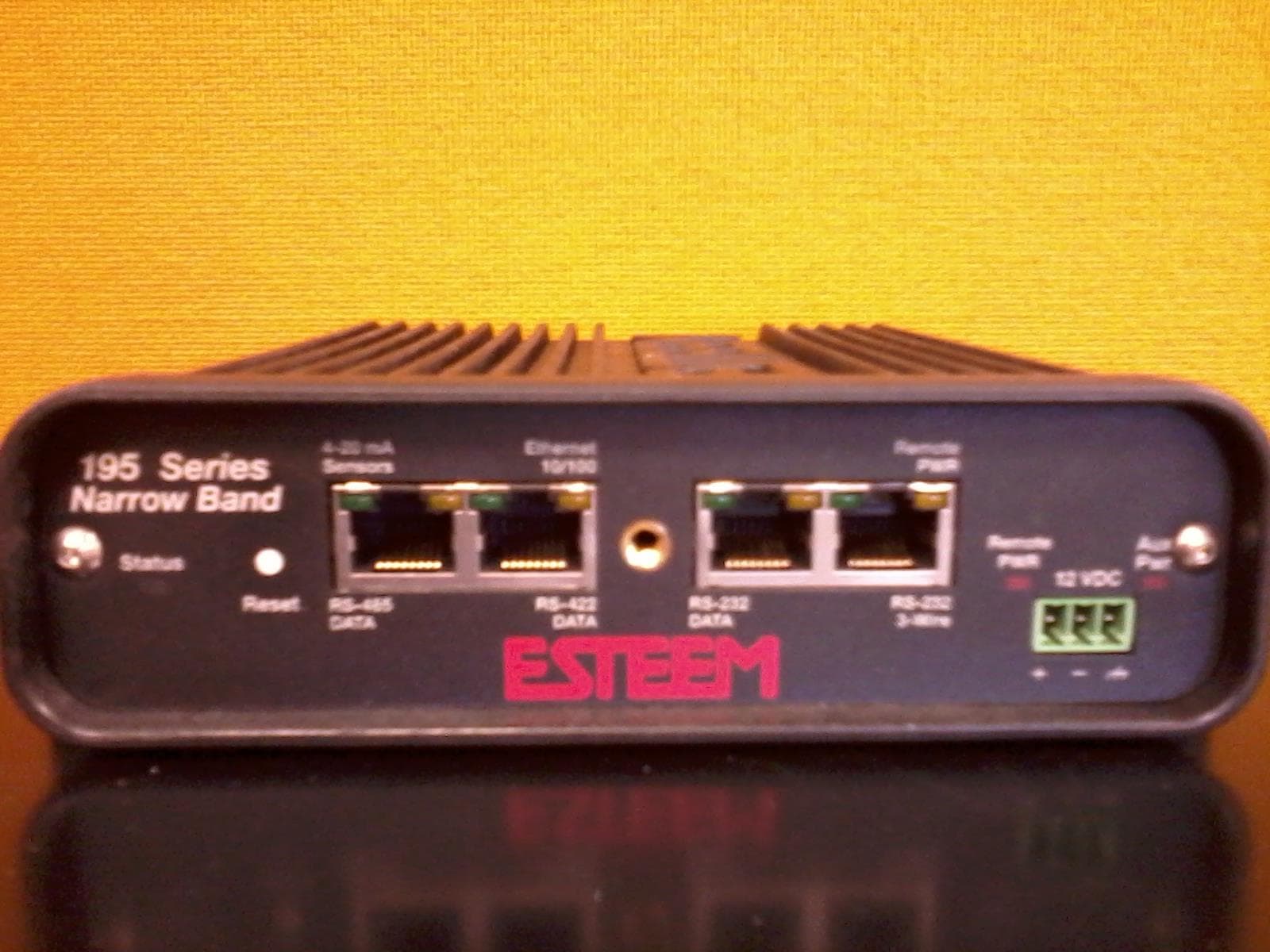
ENPESTEEM195H
Aug 12, 2014217-220MHz VHF Telemetry Modem
Equipment Class
TNB - Licensed Non-Broadcast Station Transmitter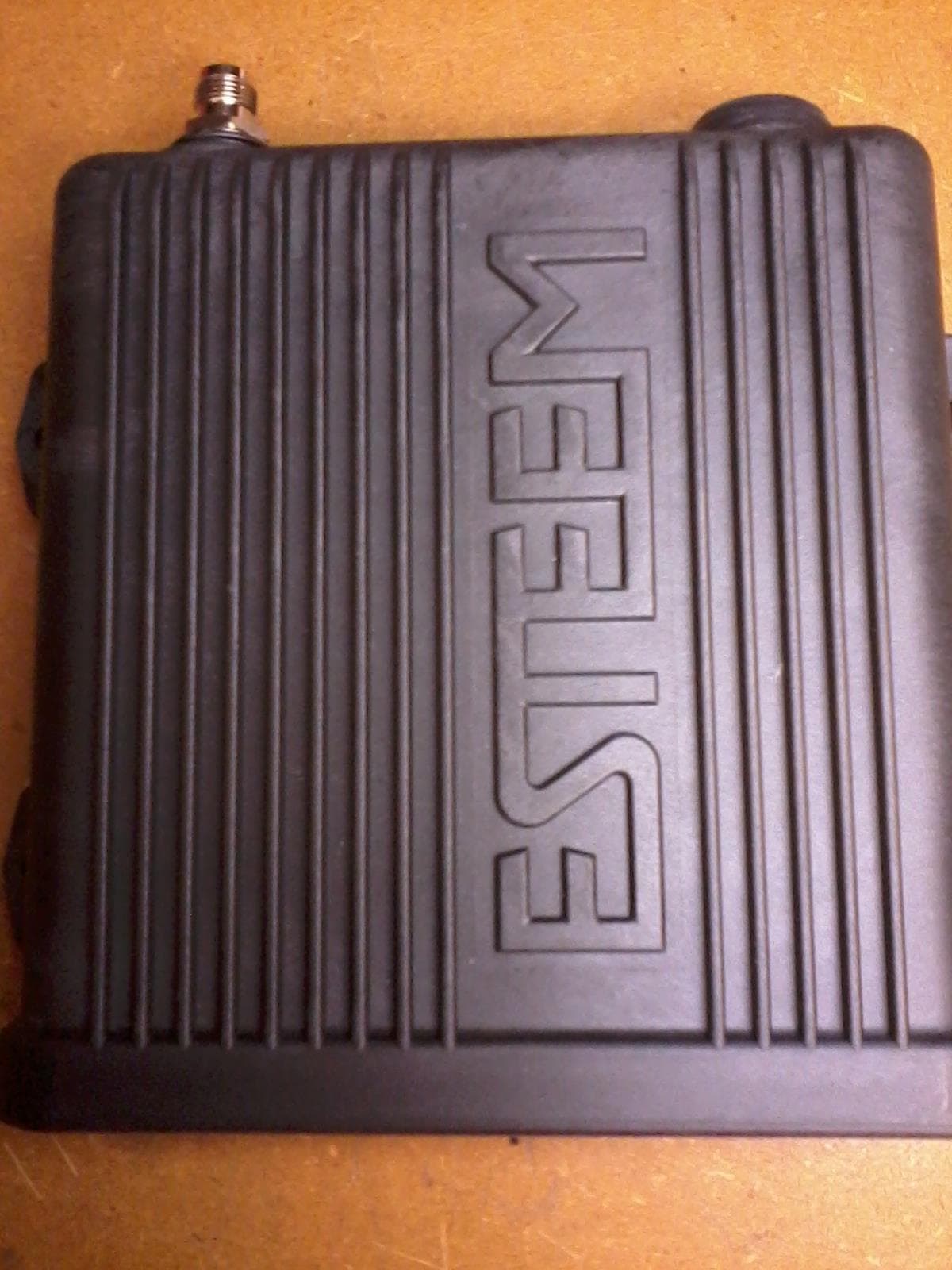
ENPESTEEM195C
Dec 19, 2013450-470MHz Narrow-band UHF modem
Equipment Class
TNB - Licensed Non-Broadcast Station Transmitter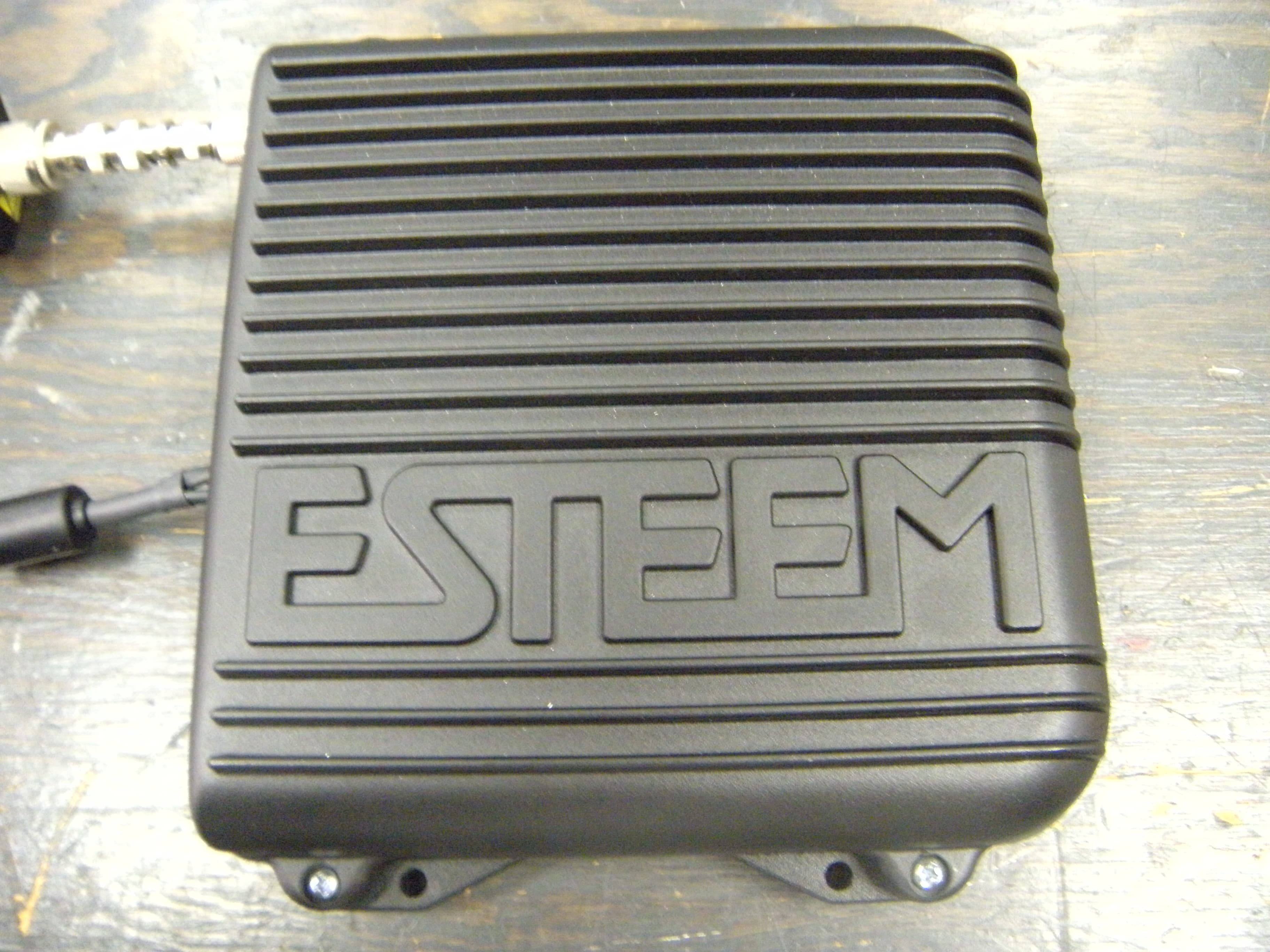
ENPESTEEM210M
Sep 05, 2013Data radio modem
Equipment Class
TNB - Licensed Non-Broadcast Station Transmitter
ENPESTEEM210C
Mar 10, 2013Data radio modem
Equipment Class
TNB - Licensed Non-Broadcast Station Transmitter
ENPESTEEM195EA
Feb 12, 2012Wireless LAN transceiver
Equipment Class
DTS - Digital Transmission System