ENPESTEEM195EAWireless LAN transceiver
Electronic Systems Technology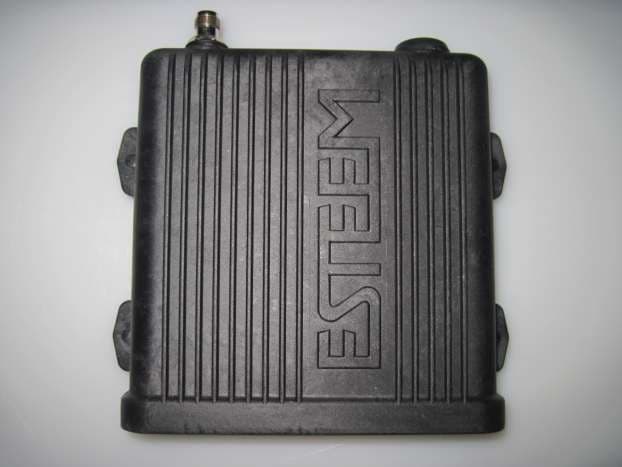
Click to zoom
Application Details
- Equipment Class
- DTS - Digital Transmission System
- Date of Grant
- Feb 12, 2012
- Application Purpose
- Original Equipment
- Date of Application
- Feb 12, 2012
- Equipment Note
- Wireless LAN transceiver
- Frequency Range
- 5745.00000000 - 5825.00000000
- Country
- United States
Documents & Files
Document Text
Text extracted from the exhibit documents filed with the FCC. Open a document above to read the original.
Users Manual
ESTeem MODEL 195Ea USER’S MANUAL Manual Revision 1 July 2011 Electronic Systems Technology, Inc. ESTeem MODEL 195Ea USER’S MANUAL Manual Revision 1.0 Firmware Version XXX and above July 2011 Prepared by: Date: Name: Eric P. Marske Title: Product Manager Approved by: Date: Name: Tom L. Kirchner Title: President COPYRIGHT INFORMATION This manual and the firmware described in it are copyrighted by EST, with all rights reserved. Under the copyright laws, this manual or the firmware internal to the ESTeem unit may not be copied, in whole or part, without the written consent of EST. Under the law, copying includes translating into another language. Electronic Systems Technology (EST) cannot guarantee that you will receive notice of a revision to the firmware described in the manual, even if you have returned a registration/warranty card received with the product. You should periodically check with your authorized EST dealer or call factory direct. EST and the EST logo are registered trademarks of Electronic Systems Technology, Inc. Simultaneously published in the United States and Canada. All rights reserved. WARRANTY INFORMATION Electronic Systems Technology, Inc., (hereinafter EST) expressly warrants its products as free of manufacturing defects for a period of one year from the date of sale to first user/customer. THERE ARE NO OTHER WARRANTIES, EXPRESS OR IMPLIED AND THERE IS EXPRESSLY EXCLUDED ALL WARRANTIES OF MERCHANTABILITY OR FITNESS FOR A PARTICULAR PURPOSE. NO OTHER WARRANTY GIVEN BY ANY EMPLOYEE, AGENT, DISTRIBUTOR OR OTHER PERSON WITH RESPECT TO THE PRODUCT SHALL BE BINDING ON EST. LIMITATION OF LIABILITY: EST's liability shall be limited to refunding of purchase price, repair or replacement of product. IN NO EVENT SHALL EST HAVE LIABILITY FOR CONSEQUENTIAL, INCIDENTAL, SPECIAL OR EXEMPLARY DAMAGES CAUSED DIRECTLY OR INDIRECTLY BY THE PRODUCT, INCLUDING BUT NOT LIMITED TO ANY INTERRUPTION OF SERVICES, LOSS OF BUSINESS OR ANTICIPATORY PROFITS. IN NO EVENT SHALL EST BE LIABLE FOR ANY DAMAGES WHATSOEVER IN EXCESS OF THE PURCHASE PRICE OF THE PRODUCT. In the event that a unit or part requires replacement or factory servicing, the following conditions apply: a) Customer must obtain from EST an authorized RMA (Return Materials Authorization) number (call 509-735-9092 Customer Support) before shipment of product or parts to EST for any reason; b) If the whole unit is shipped, it must be in its original carton and shipping components, or a carton and shipping components supplied by EST, or if parts only are shipped, they must be packaged and cushioned so as to prevent damage in transit and shipped freight prepaid; PRODUCT WILL BE CONSIDERED OUT OF WARRANTY IF: a) If the product is damaged due to improper or abnormal use, abuse, mishandling, accident or improper maintenance or failure to follow operating instruction; b) If the product is defective as a result of sand, dirt, or water damage; c) If any factory-sealed enclosure has been opened or shows evidence of an attempt to be opened; d) If defects or damage are caused by the use of unauthorized parts or unauthorized service; e) If the product has had its serial numbers altered or removed. Warranty repair form must be accompanied by proof of user's purchase of unit. Product must be shipped to the manufacturer at the following address: Electronic Systems Technology Building B1 415 North Quay Street Kennewick, Washington USA 99336 ADDITIONAL SERVICE: If EST releases an improvement update to firmware internal to the ESTeem unit during the 90 day period after the unit was purchased by the first user/customer, EST will update the applicable unit with the revised version at no charge other than for UPS handling and shipping to and from your location to the EST factory. Return of any such item must be accompanied with proof of purchase. TABLE OF CONTENTS Revised: 22 Aug 11 Page 1 EST P/N AA107A CHAPTER 1 – Introduction Before You Begin 1-1 Model 195Ea Overview 1-1 Model 195Ea Configuration Modes 1-1 Access Point Modes --------------------------------------------- 1-2 Access Point Repeater --------------------------------------------- 1-3 Self-Healing Mesh Network --------------------------------------------- 1-4 Mobile Station Modes --------------------------------------------- 1-4 Serial Applications --------------------------------------------- 1-4 CHAPTER 2 – Starting Out Three Configuration Phases 2-1 Model 195Ea Hardware Description 2-1 Front Panel Layout --------------------------------------------- 2-2 Antenna Connection Overview --------------------------------------------- 2-2 Model 195Ea Hardware Configuration 2-3 CHAPTER 3 – Example Applications Modes of Operation Description and Examples 3-1 Ethernet Bridge Mode --------------------------------------------- 3-1 Router Modes --------------------------------------------- 3-3 Mobile Client Modes --------------------------------------------- 3-4 Access Point Modes --------------------------------------------- 3-5 Programming Examples 3-7 Using ESTeem Network Configuration (ENC) Utility --------------------------------------------- 3-7 Example 1 – Point to Point Ethernet Bridge --------------------------------------------- 3-9 Example 2 – Point to Point Ethernet Bridge with Repeater --------------------------------------------- 3-10 Example 3 – Point to Multipoint with Mesh Repeater --------------------------------------------- 3-11 Example 4 – Point to Multipoint Router Mode --------------------------------------------- 3-13 Example 5 – Mobile Client Mode --------------------------------------------- 3-15 Example 6 – Access Point Mode --------------------------------------------- 3-16 Router Addressing Examples --------------------------------------------- 3-17 CHAPTER 4 – Utilities and Features ESTeem Network Configuration (ENC) Utility --------------------------------------------- 4-1 Using ESTeem Discovery Program --------------------------------------------- 4-2 Using EtherStation Sta…
Text truncated - open the document above for the full version.
Users Manual
APPENDIX A FCC INFORMATION Revised: 27 Jan 12 APX A-1 EST P/N AA107A INFORMATION TO USERS The ESTeem Model 195Ea complies with Part 15 of the FCC Rules. Operation is subject to the following two conditions: (1) This device may not cause harmful interference, and (2) this device must accept any interference received, including interference that may cause undesired operation. Note to User: Changes or modifications to this equipment not expressly approved by Electronic Systems Technology for compliance could void the user's authority to operate the equipment. Other Information Model 195Ea OFDM Spread Spectrum Device FCC Type Acceptance No: Pending Canadian Certification Number: 2163A-195EA The equipment has been tested and found to comply with the limits for a Class A digital device, pursuant to Part 15 of the FCC Rules. These limits are designed to provide reasonable protection against harmful interference when the equipment is operated in a commercial environment. This equipment generates, uses, and can radiate radio frequency energy and, if not installed and used in accordance with the instruction manual, may cause harmful interference to radio communications. Operation of this equipment in a residential area is likely to cause harmful interference in which case the user will be required to correct the interference at his own expense. APPENDIX A FCC INFORMATION Revised: 27 Jan 12 APX A-2 EST P/N AA107A FEDERAL COMMUNICATIONS COMMISSION FIELD OFFICES ALASKA 1011 E. Tudor Rd. Rm 240 Box 2955 Anchorage, AK 99510 CALIFORNIA Interstate Office Park 4542 Ruffner St., Room 370 San Diego, CA 92111-2216 Los Angeles Office (LA) Ceritos Corporate Tower 18000 Studebaker Rd., Room 660 Cerritos, CA 90701-3684 San Francisco Office (SF) 5653 Stoneridge Drive, Suite 105 Pleasanton, CA 94588-8543 COLORADO Denver Office (DV) 215 S. Wadsworth Blvd., Suite 303 Lakewood, CO 80226-1544 FLORIDA 919 Federal Bldg 51 SE First Ave. Miami, FL 33130 Tampa Office (TP) 2203 N. Lois Ave., Room 1215 Tampa, FL 33607-2356 GEORGIA Atlanta Office (AT) 3575 Koger Blvd., Suite 320 Duluth, GA 30096-4958 HAWAII 7304 Prince Kuhi Federal Building Honolulu, HI ILLINOIS Chicago Office (CG) Park Ridge Office Ctr., Room 306 1550 Northwest Highway Park Ridge, IL 60068-1460 LOUISIANA New Orleans Office (OR) 2424 Edenborn Ave. Suite 460 Metarie, LA 70001 MARYLAND 1017 Geo. Fallon Building 31 Hopkins Plaza Baltimore, MD MASSACHUSETTS Boston Office (BS) 1 Batterymarch Park Quincy, MA 02169-7495 MICHIGAN Detroit Office (DT) 24897 Hathaway Street Farmington Hills, MI 48335-1552 MINNESOTA 691 Federal Building 316 N Robert St. St. Paul, MN MISSOURI Kansas City Office (KC) 520 NE Colbern Road Second Floor Lee’s Summit, MO 64086 NEW YORK 1307 Federal Building 111 W. Huron Buffalo, NY 14202 NEW YORK New York Office (NY) 201 Varick Street, Suite 1151 New York, NY 10014-4870 OREGON 1782 Federal Building 1220 SW 3rd Avenue Portland, OR 97204 PENNSYLVANIA Philadelphia Office (PA) One Oxford Valley Office Bld. Room 404 2300 E. Lincoln Hwy Langhorne, PA 19047-1859 PUERTO RICO 747 Federal Building Carlo Chardon Ave. Hato Rey, PR 00918 TEXAS Dallas Office (DL) 9330 LBJ Freeway, Room 1170 Dallas, TX 75243-3429 5636 Federal Building 515 Rusk Avenue Houston, TX 77002 WASHINGTON DC Columbia Office (CF) 9300 East Hampton Drive Capitol Heights, MD 20743 WASHINGTON Seattle Office (ST) 11410 NE 122 nd Way Room 312 Kirkland, WA 98034-6927
Users Manual
APPENDIX B SPECIFICATIONS Model 195Ea Specifications Revised: 27 Jan 12 APX B-1 EST P/N AA107A LED Indicators Power On/Off Receiver On/Off Carrier Detect On/Off Transmitter On/Off Link Status On/Off I/O Connectors Ethernet 10/100Base T RJ-45 RS-232C Programming/Data Port RJ-45 Dual Antenna input/Outputs TNC Reverse Female Remote Input Power Power Over Ethernet Cable Direct Input Power Optional, Header Screw Connector Transmiter Frequency of Operation 5.745 to 5.825 GHz Software Selectable in 17 Channels RF Data Rates 6 to 54 Mbps (8 steps) Tx Peak Output Power 250mW to 1 Watt (Pk) (4-levels) RF Output Impedance 50 ohms Receiver Rx Sensitivity -72 dBm @54 Mbps to –92 dBm @ 6 Mbps Frame Error Rate <10% Power Power over Ethernet IEEE 802.3at Power Supply, 48 VDC @ 30 Watts Power Connector on Unit 10 to 28 VDC Receive 250 ma @ 12 VDC Transmit 1.25 A @ 12 VDC Case Dimensions 1.9 in. H x 6.7 in. W x 6.2 in. L Weight 1.25 lbs. Outdoor Pole Mounting Kit Optional, EST P/N 195PM Other Warranty 1 Year Temperature Range -30 to +60 C Humidity 95% Non-condensing FCC Type Acceptance Pending Industry Canada Type Acceptance Pending Specifications Subject to Change Without Notice APPENDIX B SPECIFICATIONS Model 195Ea Case Specifications Revised: 27 Jan 12 APX B-2 EST P/N AA107A Model AA20DMEg APPENDIX B SPECIFICATIONS Antenna Specifications Revised: 27 Jan 12 APX B-3 EST P/N AA107A Model: AA20DMEa Applications: Model 195Ea direct case mount Antenna Type: Omni-Directional, Sleeve dipole Frequency: 5.735 to 5.835 GHz Polarization: Vertical Impedance: 50 ohms Gain: 4.5 dBi (2.5 dBd) VSWR: < 1.5:1 Power: 10 W Front To Back Ratio: n/a Horizontal Beamwidth: n/a Vertical Beamwidth: n/a Antenna Material: Polyurethane Plastic Radome Recommended Mounting Hardware: n/a Antenna Connector: TNC-R Male Flexibility: +/- 20 Antenna Envelope: 7.36 in. length by .51 in. width Temperature: -20 to +65 C Weight: 28.4 grams Model No: AA20Ea Antenna Type: Omni Directional, DC Grounded Applications: Fixed base Frequency: 5.725-5.825 GHz Polarization: Vertical Impedance: 50 ohms Gain: 6 dBi (8 dBd) VSWR: 1.5:1 Typical Vertical Beamwidth: 6 degrees @ ½ power Recommended Mounting Hardware: Pole Mounting Bracket, Supplied Antenna Connector: TNC male reverse polarity with 18 in. pigtail and weatherproof boot Maximum Power Input: 25 Watts Wind Survival: 125 mph Antenna Envelope: 20.2 in. L x 1.25 in. Equivalent Flat Plate Area: .06 sq. ft Lateral Thrust at Rated Wind: 5.2 lbs feet Radome: White UV resistant fiberglass Weight: 0.5 lbs. AA20DMEa AA20Ea Caution To comply with the FCC exposure compliance requirements, a separation distance of at least ~113 cm must be maintained between the antenna and all persons. APPENDIX B SPECIFICATIONS Antenna Specifications Revised: 27 Jan 12 APX B-4 EST P/N AA107A Model No: AA205Ea Applications: Fixed base mounting Antenna Type: Directional, Linear Polarized Panel, DC grounded, Integral Bandpass Filter Frequency: 5.725-5.875 GHz Polarization: Vertical or Horizontal Impedance: 50 ohms Gain: 22 dBi (20 dBd) nominal VSWR: <1.5:1 nominal Front to Back Ratio: ≥ 25 dB Horizontal Beamwidth: 9 degrees @ ½ power Vertical Beamwidth: 9 degrees @ ½ power Antenna Material: White UV Resistant Polypropylene Recommended Mounting Hardware: Adjustable Mounting Bracket provided for wall mounting or masts between 1 in and 2.75 in. O.D. Antenna Connector: TNC male reverse polarity with 18 in. pig-tail and weatherproof boot. Maximum Power Input: 20 Watts Antenna Envelope: 14.5 in. length by 14.5 in. height by 1.75 in. depth Operating Temperature: -40 to +85 F. Weight: 3.5 lbs. Model AA205Ea Caution To comply with the FCC exposure compliance requirements, a separation distance of at least ~113 cm must be maintained between the antenna and all persons.
Users Manual
CHAPTER 8 ANTENNA SETUPS Revised: 27 Jan 12 8-1 EST P/N AA107A ANTENNA AND CABLE CONFIGURATIONS Warning: Only the tested cable lengths and antennas provided by EST meet the FCC and DOC maximum peak output power requirements. Any other combination of antennas or coax cables is not authorized. EST offers different types of antennas for both indoor and outdoor configurations. This device has been designed to operate with the antennas listed below, and having a maximum gain of 22 dBi. Antennas not included in this list or having a gain greater than 22dBi are strictly prohibited for use with this device. The required antenna impedance is 50 ohms. Part Number: AA20DMa Omni-directional direct mount antenna, 4.5 dBi gain. Indoor and outdoor applications. There must be a minimum separation distance of 23 cm. from the antenna to the user. See Warnings. Part Number: AA20Ea Omni-directional external pole mount antenna, 10 dBi gain with 18 inch integral feedline and connector. Outdoor applications. There must be a minimum separation distance of 23 cm. from the antenna to the user. See Warnings. Part Number: AA205Ea Directional linear panel, pole mount antenna, 22 dBi gain with 18 inch integral feedline, bandpass filter and connector. Point to point and point to multi-point outdoor applications. There must be a minimum separation distance of 50 cm. from the antenna to the user. See Warnings. This radio transmitter (ESTeem 195Ea - 2163A-195EA) has been approved by Industry Canada to operate with the antenna types listed above with the maximum permissible gain and required antenna impedance for each antenna type indicated. Antenna types not included in this list, having a gain greater than the maximum gain indicated for that type, are strictly prohibited for use with this device. (Le présent émetteur radio (ESTeem 195Ea – 2163A-195EA) a été approuvé par Industrie Canada pour fonctionner avec les types d'antenne énumérés au-dessous et ayant un gain admissible maximal et l'impédance requise pour chaque type d'antenne. Les types d'antenne non inclus dans cette liste, ou dont le gain est supérieur au gain maximal indiqué, sont strictement interdits pour l'exploitation de l'émetteur.) Antenna Port A Warnings: Only pre-made coax cables from the factory used in conjunction with either the omni-directional and directional antennas meet all FCC Section 15.247(b) EIRP maximum power requirements. To comply with the FCC exposure compliance requirements, a separation distance of at least 20 cm must be maintained between the antenna and all persons. CHAPTER 8 ANTENNA SETUPS Revised: 27 Jan 12 8-2 EST P/N AA107A ASSEMBLING THE AA195PM TWO HOLE OUTDOOR POLE MOUNTING KIT The AA195PM mounting kit contains everything required for pole mounting and weatherproofing the ESTeem Model 195E for outdoor installations. The 195E with AA195PM mounting kit can be directly mounted to a round pole from 1.25” to a diameter of 2.25” OD. Any mounting structure greater than 2” requires hose clamp strapping run through the Pole Mount Brackets. The mounting kit requires the following assembly: 1. If you purchased an AA195PM mounting kit with your Model 195E, the kit will be packed in the same packing box as the ESTeem (Figure 1). 2. Remove and inventory the two (2) Pole Mounting Brackets, one (1) Two-Hole Face Plate Cover (with single port cover installed), one (1) Heat Shield and (1) AA195PM Hardware bag from the packing box (Figure 1). Report any missing or damaged items to ESTeem Customer Support (509-735-9092 Phone) as soon as possible for replacement. Figure 1: Packet Box Contents Figure 2: AA195PM Hardware Contents (2) Square Bend U-Bolts with Hardware (2) Pole Mount Clamps (4) 10-24 Pan Screws (2) Ethernet Cable Boot (1) Weather Proof Boot for Antenna Port B (if not used) (2) Direct Mount Antenna Boots for ESTeem Approved Direct Mount Antenna Only CHAPTER 8 ANTENNA SETUPS Revised: 27 Jan 12 8-3 EST P/N AA107A 3. Inventory the AA195PM Hardware bag for all the components listed in Figure 2. 4. Assemble the two Pole Mounting Brackets with the included U-bolts, hardware and Pole Mount Clamps. Reference Figure 3. 5. Place the four supplied 10-24 x 1” Phillips Pan Head screws through the mounting holes of the Heat Shield and attach to the to the top of the ESTeem 195E (Figure 4). Figure 3: Pole Mount Assembly Figure 4: Heat Shield Attachment CHAPTER 8 ANTENNA SETUPS Revised: 27 Jan 12 8-4 EST P/N AA107A 6. Attach the two Pole Mounting Brackets to the ESTeem Model 195E with the 10-24 x 1” Phillips Pan Head screws through the top of the heat shield. Reference Figure 5 (Heat Shield removed for detail). 7. Assemble the outdoor rated CAT-5e Ethernet cable (Not Provided) with the supplied Ethernet Cable Boot (Figure 6). 8. Feed the CAT-5e Ethernet connector(s) through the Face Plate Cover and secure the Ethernet Cable Boot to the cover. Reference Figure 7. NOTE: The Ethernet cable boot must be installed before the RJ-45 end is installed. If using the ESTeem AA09.1 outdoor Ethernet cable, verify that the Ethernet cable boot end is routed toward the ESTeem 195E. Figure 5: Pole Mount Connection to Case (Heat Shield Removed for Detail) Ethernet Cable Boot Figure 6: Ethernet Cable Assembly CHAPTER 8 ANTENNA SETUPS Revised: 27 Jan 12 8-5 EST P/N AA107A 9. Route the CAT-5e Ethernet cable through the molded strain-relief fins in the Face Plate Cover (Figure 8) to secure the cable and provide strain-relief for the connector. If a second Ethernet cable is installed, remove the second port cover and route cable. 10. Plug the CAT-5e Ethernet cable to the Model 195E’s Ethernet port and secure the Face Plate Cover with the attached thumb screw. Verify that the weatherproof seal on the Face Plate Cover is sealed against the outer rim of the Model 195E. Reference Figure 9. 11. Attach the antenna connector boots as show in Figure 10 for either dual attached antennas or external antennas. You are now ready to mount the ESTeem Model 195E Figure 8…
Text truncated - open the document above for the full version.
Cover Letter(s)
DATE: 12/1/2011 FCC ID: ___ENPESTEEM195EA________ Product Name: ___ESTEEM 195EA________ Request for Confidentiality Pursuant to Sections 0.457 and 0.459 of the commissions rules, we hereby request that the following documents be held confidential: (List here the documents for which you are seeking confidentiality – for example) •Schematics •Block diagram •Operational Description These materials contain trade secrets and proprietary information and are not customarily released to the public. The public disclosure of this information might be harmful to the company and provide unjustified benefits to our competitors. Dated thisDecember Day of 1st 20 11 By:D. Brent Strecker Signature Printed Title:V.P. Engineering On behalf of :Electronic Systems Technology Telephone:509 735-9092 x105 ELECTRONIC SYSTEMS TECHNOLOGY, INC. 415 North Quay St. • Kennewick, WA 99336 • Phone (509) 735-9092 • Fax (509) 783-5475
RF Exposure Info
§ 15.247(i) Maximum Permissible Exposure RF Exposure Requirements: §1.1307(b)(1) and §1.1307(b)(2): Systems operating under the provisions of this section shall be operated in a manner that ensures that the public is not exposed to radio frequency energy levels in excess of the Commission’s guidelines. RF Radiation Exposure Limit: §1.1310: As specified in this section, the Maximum Permissible Exposure (MPE) Limit shall be used to evaluate the environmental impact of human exposure to radiofrequency (RF) radiation as specified in Sec. 1.1307(b), except in the case of portable devices which shall be evaluated according to the provisions of Sec. 2.1093 of this chapter. MPE Limit Calculation: EUT’s operating frequencies @ 5725-5850MHz; highest conducted power = 29.99 dbm (peak) therefore, Limit for Uncontrolled exposure: 1 mW/cm 2 or 10 W/m 2 EUT maximum antenna gain = 22 dBi. Equation from page 18 of OET 65, Edition 97-01 S = PG / 4R 2 or R = √PG / 4S where, S = Power Density (1 mW/cm 2 ) P = Power Input to antenna (997.7mW) G = Antenna Gain (158.5 numeric) R = (997.7*158.5/ 4*3.14*1.0) 1/2 = (158124.8 / 12.56) 1/2 = 112.2cm
RF Exposure Info
INFRASTRUCTURE ANTENNAS Directional Panels Directional Linear Polarized Panel Antennas Technical Data Maximum Power: 20 watts Polarization: Vertical Linear Nominal Impedance: 50 ohms VSWR: < 2.0 (FP8241850-10VP only) < 1.5 (all models except FP8241850-10VP) Front to Back Ratio: 25 Radome Material: UL94-V0 ASA radome Mounting Method: Adjustable mount is included. Suitable for pipe or wall installation. The FP directional panel antenna series is designed to cover various frequen- cies, obtaining maximum gain with an attractive, low profi le package. All of the models provide effi cient and stable performance across the band and can be mounted indoors or outdoors. Features • UL94-V0 ASA radome and PC board conform to UL’s high fl ame retardant rating, allowing maximum installation fl exibility. Meets stringent building code requirements. • Attractive, low profi le housing. Blends well with indoor and outdoor envi- ronments where aesthetic considerations are important. • Adjustable mounting brackets for outdoor installation. • Panel mounted type N female connector. RF/Electrical Specifi cations Mechanical Specifi cations FRONT VIEW FP8241850-10VP14.5” x 14.5” x 1.75” (340 x 340 x 30 mm) 3.5 lbs (1.6 kg) -40°C to +85°C FP3637-18VP14.5” x 14.5” x 1.75” (340 x 340 x 30 mm) 3.5 lbs (1.6 kg) -40°C to +85°C FP4959-22VP14.5” x 14.5” x 1.75” (340 x 340 x 30 mm) 3.5 lbs (1.6 kg) -40°C to +85°C FP8241850-10VP 824-960 MHz 1710-2170 MHz 10 dBi 11 dBi 40° 30° 52° 66° FP3637-18VP3.6-3.75 GHz18 dBi18°18° FP4959-22VP4.9-5.9 GHz22 dBi9°9° MOUNT VIEW Model Frequency Range Gain 3 dB Horizontal Beamwidth 3 dB Vertical Beamwidth ModelDimensions Antenna Weight (Mass) Temperature Range PCTEL, Inc. WEB: www.antenna.com 137
RF Exposure Info
251 PCTEL Antenna Products Group, Inc. ORDER (800) 323-9122 http://www.maxrad.com XtremeWave™ MFB Series General Specifications: Radome Material: UV resistant pultruded fiberglass Polarization: Vertical Lightning Protection: Not standard, but all models can be ordered with DC grounding. Add “DC” to the part number to order the antenna with DC grounding. Nominal Impedance: 50 Ohms Mounting Base Diameter: 1.25 inches Mounting Method (sold separately): MMK1924 – L bracket mount for wall or pipe mount MMK8A - Aluminum extruded bracket for mast mounting Termination: N female N male connector option available. To order, add “NM” to part number. Features and Benefits: •UV stable, pultruded fiberglass radome. Allows outdoor installation even in harsh climates. •Vented system design. Provides reliable performance by protecting the electrical design against extreme moisture and/or temperatures. •Thread relief on connector. Improved accessibility for taping reduces installation time and improves overall effectiveness. •Internal o-ring seal in the base of the antenna with integrated connector at the base. Assures a watertight seal to prevent water from migrating into the antenna connector. The XtremeWave™ wireless broadband omnidirectional antennas are designed to provide maximum performance and reliability under the toughest weather conditions. These antennas feature a UV stable, vented radome that provides ultimate protection against weather elements. They can be mast or wall mounted. Public Safety Band, ISM,UNII and WiMAX Omnidirectional Base Station Antenna Series MMK1924 Vented System MFB49009 MFB58009 MMK8A Mechanical Specifications 252 PCTEL Antenna Products Group, Inc. ORDER (800) 323-9122 http://www.maxrad.com Specifications Model #Frequency RangeGain Bandwidth @ 1.5:1 VSWR Vertical Beamwidth @ 1/2 Power VSWR Maximum Power MFB490094.9-5.0 GHz9 dBi100 MHz8°< 1.5:125 Watts MFB515105.15-5.35 GHz10 dBi200 MHz7°< 1.5:125 Watts MFB580095.725-5.875 GHz9 dBi150 MHz8°< 1.5:125 Watts MFB580105.725-5.825 GHz10 dBi100 MHz6°< 1.5:125 Watts Model # Wind Survival Equivalent Flat Plate Area Lateral Thrust @ Rated Wind Bending Moment @ Rated Wind HeightWeight MFB49009125 mph.06 ft²5.2 lbs4.4 ft-lbs20.2” (513.1 mm)0.5 lbs (0.226 kg) MFB51510125 mph.06 ft²5.2 lbs4.4 ft-lbs20.2” (513.1 mm)0.5 lbs (0.226 kg) MFB58009125 mph.046 ft²4.1 lbs2.7 ft-lbs15.7” (398.8 mm)0.43 lbs (0.195 kg) MFB58010125 mph.06 ft²5.2 lbs4.4 ft-lbs20.2” (513.1 mm)0.5 lbs (0.226 kg) Electrical Specifications 253 PCTEL Antenna Products Group, Inc. ORDER (800) 323-9122 http://www.maxrad.com Patterns 10 190 20 200 30 210 40 220 50 230 60 240 70 250 80 260 90 270 100 280 110 290 120 300 130 310 140 320 150 330 160 340 170 350 1800 −35−35−30−30−25−25−20−20−15−15−10−10−5−5 10 190 20 200 30 210 40 220 50 230 60 240 70 250 80 260 90 270 100 280 110 290 120 300 130 310 140 320 150 330 160 340 170 350 1800 −35−35−30−30−25−25−20−20−15−15−10−10−5−5 MFB49009 Elevation Cut MFB51510 Elevation Cut 254 PCTEL Antenna Products Group, Inc. ORDER (800) 323-9122 http://www.maxrad.com 10 190 20 200 30 210 40 220 50 230 60 240 70 250 80 260 90 270 100 280 110 290 120 300 130 310 140 320 150 330 160 340 170 350 1800 −35−35−30−30−25−25−20−20−15−15−10−10−5−5 10 190 20 200 30 210 40 220 50 230 60 240 70 250 80 260 90 270 100 280 110 290 120 300 130 310 140 320 150 330 160 340 170 350 1800 −35−35−30−30−25−25−20−20−15−15−10−10−5−5 MFB58009 Elevation Cut MFB58010 Elevation Cut Patterns
Test Report
MET Laboratories, Inc. Safety Certification - EMI - Telecom Environmental Simulation 914 WEST PATAPSCO AVENUE ! BALTIMORE, MARYLAND 21230-3432 ! PHONE (410) 354-3300 ! FAX (410) 354-3313 33439 WESTERN AVENUE ● UNION CITY, CALIFORNIA 94587 ● PHONE (510) 489-6300 ● FAX (510) 489-6372 3162 BELICK STREET ● SANTA CLARA, CALIFORNIA 95054 ● PHONE (408 748-3585 ● FAX (510) 489-6372 The Nation’s First Licensed Nationally Recognized Testing Laboratory January 30, 2012 Electronic Systems Technology 415 North Quay St. Bldg. B-1 Kennewick, WA 99336 Dear Brent Strecker, Enclosed is the EMC Wireless test report for compliance testing of the Electronic Systems Technology, ESTeem 195Ea as tested to the requirements of Title 47 of the CFR, Ch. 1 (10-1-06 ed.), Part 15, Subpart B, ICES-003, Issue 4 February 2004 for a Class A Digital Device and FCC Part 15 Subpart C, RSS-210, Issue 8, Dec. 2010 for Intentional Radiators. Thank you for using the services of MET Laboratories, Inc. If you have any questions regarding these results or if MET can be of further service to you, please feel free to contact me. Sincerely yours, MET LABORATORIES, INC. Jennifer Warnell Documentation Department Reference: (\Electronic Systems Technology\EMCS33737-FCC247) Certificates and reports shall not be reproduced except in full, without the written permission of MET Laboratories, Inc. Electromagnetic Compatibility Electronic Systems Technology Cover Page ESTeem 195Ea CFR Title 47, Part 15B, 15.247; RSS-210, Issue 8, Dec. 2010 & ICES-003 MET Report: EMCS33737-FCC247 © 2012, MET Laboratories, Inc. Page ii of x DOC-EMC702 6/18/2009 Electromagnetic Compatibility Criteria Test Report for the Electronic Systems Technology ESTeem 195Ea Tested under the FCC Certification Rules contained in Title 47 of the CFR, Parts 15 Subpart B & ICES-003 for Class A Digital Devices & 15.247 Subpart C & RSS-210, Issue 8, Dec. 2010 for Intentional Radiators MET Report: EMCS33737-FCC247 January 30, 2012 Prepared For: Electronic Systems Technology 415 North Quay St. Bldg B-1 Kennewick, WA 99336 Prepared By: MET Laboratories, Inc. 3162 Belick St. Santa Clara, CA 95054 Electromagnetic Compatibility Electronic Systems Technology Cover Page ESTeem 195Ea CFR Title 47, Part 15B, 15.247; RSS-210, Issue 8, Dec. 2010 & ICES-003 MET Report: EMCS33737-FCC247 © 2012, MET Laboratories, Inc. Page iii of x DOC-EMC702 6/18/2009 Electromagnetic Compatibility Criteria Test Report for the Electronic Systems Technology ESTeem 195Ea Tested under the FCC Certification Rules contained in Title 47 of the CFR, Parts 15 Subpart B & ICES-003 for Class A Digital Devices & 15.247 Subpart C & RSS-210, Issue 8, Dec. 2010 for Intentional Radiators Anderson Soungpanya, Project Engineer Jennifer Warnell Electromagnetic Compatibility Lab Documentation Department Engineering Statement: The measurements shown in this report were made in accordance with the procedures indicated, and the emissions from this equipment were found to be within the limits applicable. I assume full responsibility for the accuracy and completeness of these measurements, and for the qualifications of all persons taking them. It is further stated that upon the basis of the measurements made, the equipment tested is capable of operation in accordance with the requirements of the FCC Rules Parts 15B, 15.247 and Industry Canada standards ICES-003, Issue 4 February 2004, RSS-210, Issue 8, Dec. 2010 under normal use and maintenance. Shawn McMillen, Wireless Manager, Electromagnetic Compatibility Lab Electromag…
Text truncated - open the document above for the full version.
Contact Information
Applicant
Todd Elliott(Engineer)
Technical Contact
Electronic Systems Technology, Inc.D. Brent Strecker
[email protected]509-739-9092
415 North Quay Street · Kennewick · United States
Non-Technical Contact
Electronic Systems Technology, Inc.Jon Correio
509-739-9092
Test Firm
EUROFINS ELECTRICAL AND ELECTRONIC TESTING NA, INCGreg Kovolenko
Technical Specifications
| # | Rule Parts | Frequency Range | Power Output |
|---|---|---|---|
| 1 | 15C | 5.75 GHz - 5.83 GHz | 997.00 mW |
Other Applications from Electronic Systems Technology
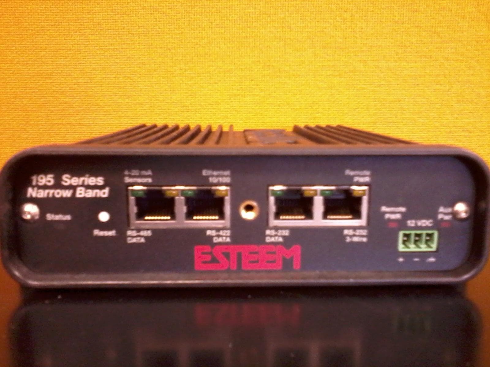
ENPESTEEM195H
Aug 12, 2014217-220MHz VHF Telemetry Modem
Equipment Class
TNB - Licensed Non-Broadcast Station Transmitter
ENPESTEEM195C
Dec 19, 2013450-470MHz Narrow-band UHF modem
Equipment Class
TNB - Licensed Non-Broadcast Station Transmitter
ENPESTEEM210M
Sep 05, 2013Data radio modem
Equipment Class
TNB - Licensed Non-Broadcast Station Transmitter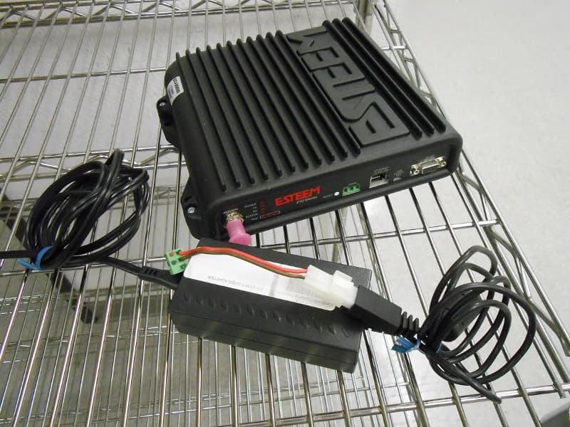
ENPESTEEM210C
Mar 10, 2013Data radio modem
Equipment Class
TNB - Licensed Non-Broadcast Station Transmitter
ENPESTEEM195ED-1
Mar 23, 2011Wireless LAN transceiver
Equipment Class
DTS - Digital Transmission System