ENPESTEEM195C450-470MHz Narrow-band UHF modem
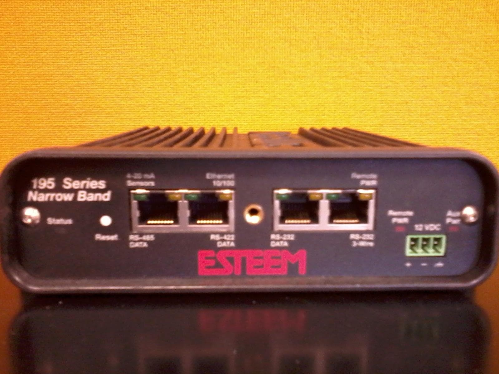
Electronic Systems Technology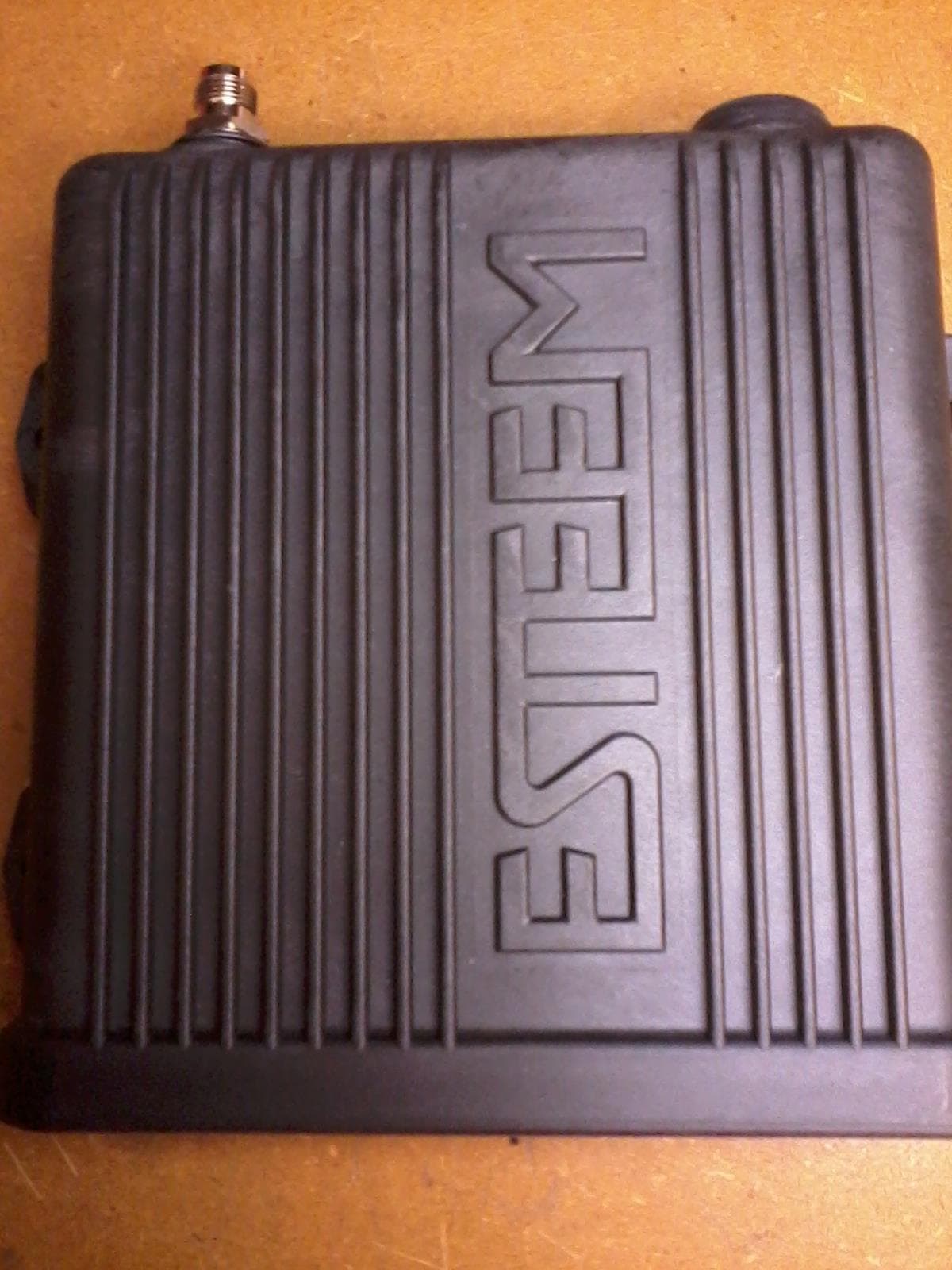
Click to zoom
Application Details
- Equipment Class
- TNB - Licensed Non-Broadcast Station Transmitter
- Date of Grant
- Dec 19, 2013
- Application Purpose
- Original Equipment
- Date of Application
- Dec 19, 2013
- Equipment Note
- 450-470MHz Narrow-band UHF modem
- Frequency Range
- 450.00000000 - 470.00000000
- Country
- United States
Documents & Files
Document Text
Text extracted from the exhibit documents filed with the FCC. Open a document above to read the original.
Users Manual
ESTeem USER’S MANUAL Models 195C – 195M Manual Revision 1.0 September 2013 Electronic Systems Technology, Inc. Author: Date: Name: Eric P. Marske Title: Product Support Manager Approved by: Date: Name: Tom L. Kirchner Title: President Electronic Systems Technology, Inc. Building B1 415 N. Quay Street Kennewick, WA 99336 Phone: 509-783-9092 Fax: 509-783-5472 E-mail: [email protected] Web Site: www.esteem.com Copyright© 2013 by Electronic Systems Technology, Inc. All rights reserved. Printed in the United States of America. No part of this publication may be reproduced, stored in a retrieval system, or transmitted, in any form or by any means, electronic, mechanical, photocopying, recording, or otherwise, without the prior written permission of Electronic Systems Technology. PRODUCT WARRANTY ELECTRONIC SYSTEMS TECHNOLOGY, INC. Specifications subject to change without notice 415 North Quay Street • Kennewick, WA 99336 www.esteem.com Phone (509) 735-9092 • Fax (509) 783-5475 Revised: 26 September 2013 Electronic Systems Technology, Inc., (hereinafter EST) expressly warrants its products as free of manufacturing defects for a period of one year from the date of sale to first user/customer. THERE ARE NO OTHER WARRANTIES, EXPRESS OR IMPLIED AND THERE IS EXPRESSLY EXCLUDED ALL WARRANTIES OF MERCHANTABILITY OR FITNESS FOR A PARTICULAR PURPOSE. NO OTHER WARRANTY GIVEN BY ANY EMPLOYEE, AGENT, DISTRIBUTOR OR OTHER PERSON WITH RESPECT TO THE PRODUCT SHALL BE BINDING ON EST. LIMITATION OF LIABILITY: EST's liability shall be limited to refunding of purchase price, repair or replacement of product. IN NO EVENT SHALL EST HAVE LIABILITY FOR CONSEQUENTIAL, INCIDENTAL, SPECIAL OR EXEMPLARY DAMAGES CAUSED DIRECTLY OR INDIRECTLY BY THE PRODUCT, INCLUDING BUT NOT LIMITED TO ANY INTERRUPTION OF SERVICES, LOSS OF BUSINESS OR ANTICIPATORY PROFITS. IN NO EVENT SHALL EST BE LIABLE FOR ANY DAMAGES WHATSOEVER IN EXCESS OF THE PURCHASE PRICE OF THE PRODUCT. In the event that a unit or part requires replacement or factory servicing, the following conditions apply: a) Customer must obtain from EST an authorized RMA (Return Materials Authorization) Number before shipment of product or parts to EST for any reason; b) If the whole unit is shipped, it must be in its original carton and shipping components, or a carton and shipping components supplied by EST, or it parts only are shipped, they must be packaged and cushioned so as to prevent damage in transit and shipped freight prepaid; PRODUCT WILL BE CONSIDERED OUT OF WARRANTY IF: a) If the product is damaged due to improper or abnormal use, abuse, mishandling, accident or improper maintenance or failure to follow operating instruction; b) If the product is defective as a result of sand, dirt, or water damage; c) If any factory-sealed enclosure has been opened or shows evidence of an attempt to be opened; d) If defects or damage are caused by the use of unauthorized parts or unauthorized service; e) If the product has had its serial numbers altered or removed. Warranty repair form must be accompanied by proof of user's purchase of unit. Product must be shipped to the manufacturer at the following address: Electronic Systems Technology 415 North Quay Street Kennewick, Washington USA 99336 ADDITIONAL SERVICE: If EST releases an improvement update to firmware internal to the ESTeem unit during the 90 day period after the unit was purchased by the first user/customer, EST will update the applicable unit with the revised version at no charge other than for UPS handling and shipping to and from your location to the EST factory. Return of any such item must be accompanied with proof of purchase. TABLE OF CONTENTS Revised: 26 Sep 13 Page 1 EST P/N AA107-195C/MCM CHAPTER 1 – Introduction Before You Begin 1-1 Model 195C/M Overview 1-1 Model 195C/M Configuration Modes 1-1 Access Point Modes ---------------------------------------------1-2 Access Point Repeater ---------------------------------------------1-3 Self-Healing Mesh Network ---------------------------------------------1-3 Station Modes ---------------------------------------------1-4 RS-232 Serial Applications ---------------------------------------------1-5 CHAPTER 2 – Starting Out Three Configuration Phases 2-1 Model 195C/M Hardware Description 2-1 Front Panel Layout ---------------------------------------------2-2 Antenna Connection Overview ---------------------------------------------2-2 CHAPTER 3 – Example Applications Modes of Operation Description and Examples 3-1 Ethernet Bridge Mode ---------------------------------------------3-1 Router Modes ---------------------------------------------3-3 Mobile Client Modes ---------------------------------------------3-4 Programming Examples 3-7 Using ESTeem Network Configuration (ENC) Utility ---------------------------------------------3-7 Example 1 – Point to Point Ethernet Bridge ---------------------------------------------3-9 Example 2 – Point to Point Ethernet Bridge with Repeater ---------------------------------------------3-10 Example 3 – Point to Multipoint with Mesh Repeater ---------------------------------------------3-11 Example 4 – Point to Multipoint Router Mode ---------------------------------------------3-13 Example 5 – Mobile Client Mode ---------------------------------------------3-15 Example 6 – Access Point Mode ---------------------------------------------3-16 Router Addressing Examples ---------------------------------------------3-17 CHAPTER 4 – Utilities and Features ESTeem Network Configuration (ENC) Utility --------------------------------------------- 4-1 Using ESTeem Discovery Program --------------------------------------------- 4-2 Using EtherStation Status Program --------------------------------------------- 4-5 Setting Local Time 195C/M --------------------------------------------- 4-6 Configuring Time Server --------------------------------------------- 4-7 Simple Network Management Protocol (SNMP) ---------------------------------------…
Text truncated - open the document above for the full version.
Users Manual
CHAPTER 7 REPEATING FEATURES Revised: 1 Oct 13 7-4 EST P/N AA107-195CM determine routing and which paths will be blocked. On a wired Ethernet network, the location of the Root Bridge is not really important, but in a wireless network selection of the Root Bridge is critical to the wireless network routing. Let’s use one of the Example network diagrams from Chapter 3 to continue the discussion (Figure 4). STP Phases The following sections describe the process of the STP in the ESTeem Model 195C/M as how it would happen in the above example. Learning Phase - Once properly configured, each Model 195C/M will begin to search out the other Model 195C/M units in radio range that are programmed in the AP Repeater Peer table. All Model 195C/M’s will calculate their routes to every Model 195C/M in the network based upon the lowest “path length” to the Root Bridge. Path length is the total number of wireless links (repeater peer links) to transmit a packet through the wireless network to the Root Bridge. Note: The Root Bridge in a network should be the Model 195C/M where the majority of the data flow is processed. In every wireless network of two or more radios, the Root Bridge should be user defined. If not defined, the ESTeem 195C/M with the lowest MAC address will be designated as the Root Bridge. In Figure 4, the Plant network (Example 1) is the most logical location for the Root Bridge based upon the amount of data flow. Setting this site as the root bridge is discussed below in Root Bridge. Blocking and Forwarding Phase – To ensure you do not have a network loop situation due to redundant paths in your wireless network, the Model 195C/M will recognize and disable (block) one or more redundant links and provide back up links should the primary link fail. This establishes a wireless mesh network with a series of forwarding links, based upon the shortest path length to the Root Bridge. For example, looking at Figure 4, the Remote Building has two routes to the Root Bridge (Plant Network – Example #1); directly to the site and through the repeater. The direct link between the two sites is the shortest route (lowest Path Length) and will be selected as the primary route unless overridden by manually changing the Path Length in the configuration. Path Length If more than one communication path to the Root Bridge is found, the 195C/M must determine which route to take based upon the lowest Path Length. The default path length to all links in the 195C/M network is 1. If the Path Lengths are equal then the lowest MAC address will determine the priority route. In the ESTeem Mesh Network we want to directly control all data flow so do not want the routes to be automatically determined. Looking again at our Example in Figure 4, if we made no changes to the default path length of 1 (note values in Figure 3) the lowest path cost would be direct from the Remote Building to the Root Bridge (Plant Network). Link Description Total Path Length Direct from Remote Building 1 Remote Build to Root Bridge Through Repeater 2 (Length 1 to repeater + Length 1 to Master = 2) To configure the 195C/M to select the repeater as the primary radio path, set the path length value for the direct link greater than 2 (such as a value of 3) to make this the primary radio path. The lowest path length will identify the highest priority. The Model 195C/M will use this routing, but also switch to direct communication if the repeater were to disappear. Root Bridge In any Access Point Repeater network consisting of more than two sites, one Model 195C/M should be designated as the Root Bridge. Only one Model 195C/M can be designated as the Root Bridge in a given network and should be located where the majority of the Ethernet data flow is processed. This site may be the Master location in a SCADA network or could be configured CHAPTER 7 REPEATING FEATURES Revised: 1 Oct 13 7-5 EST P/N AA107-195CM at a repeater site. Selection is important because all Model 195C/M’s NOT configured as the Root Bridge will choose routing based upon the Path Length to the Root Bridge. If you have any question as to which site in your AP Repeater application should be the Root Bridge, contact ESTeem Customer Support at 509-735-9092 or e-mail your application to [email protected]. The Root Bridge will be selected in one of two ways: the Root Bridge can be manually set (recommended) during the configuration of the Repeater Peer table (Figure 3) or the Root Bridge designation will default to the lowest MAC address of all the Model 195C/M’s in the network. The manual Root Bridge configuration is located in the “Advanced Settings” section. Redundant Backup Figure 4: Redundant Backup Diagram The ESTeem Model 195C/M configured in Access Point Repeater mode will automatically function as a redundant backup if two Model 195C/M’s are installed at the same location (Figure 4). If two Model 195C/M’s are connected to the same switch, one of the Model 195C/M’s will be Blocked when the Spanning Tree Protocol is completed. The network will continue to use this route until any problem with the original Model 195C/M is detected and the second Model 195C/M will begin operation at that site. Redundant Master Configuration The configuration in Figure 4 will also provide a redundant backup for the Master Site (Root Bridge). Configure both Model 195C/M’s as Root Bridges (see above) giving the primary Root Bridge a value of 1 and the secondary Root Bridge a value of 2. CHAPTER 8 ANTENNA SETUPS Revised: 1 Oct 13 8-1 EST P/N AA107-195CM ESTeem offers different types of antennas ranging from ¼ wave to 5/8 wave in physical size. The user choice is dependent on the application. Communications in the VHF and UHF bands are normally over "Line of Sight (LOS)". Looking from the antenna of one wireless modem you must be able to see the antenna of the wireless modem you wish to communicate with. If a large object obstructs the line of sight view it is unlikely that satisfactory communications…
Text truncated - open the document above for the full version.
Cover Letter(s)
ELECTRONIC SYSTEMS TECHNOLOGY, INC. 415 North Quay St. • Kennewick, WA 99336 Phone (509) 735-9092 • Fax (509) 783-5475 1 of 1 2013-11-05 MET Laboratories, Inc. 914 West Patapsco Avenue Baltimore, MD 21230 RE: CONFIDENTIALITY REQUEST FOR 195C, FCC ID: ENPESTEEM195C To Whom It May Concern: This letter serves as an official request for confidentiality under sections 0.457 and 0.459 of CFR 47. We have requested that the schematics, block diagram, bill-of-materials, and operational description documents required to be submitted with this application be permanently withheld from public review. These materials contain trade secrets and proprietary information and are not customarily released to the public. The public disclosure of this information might be harmful to the company and provide unjustified benefits to our competitors. Sincerely, Todd Elliott
RF Exposure Info
Electromagnetic Compatibility Criteria for Intentional Radiators § 15.247(b) RF Exposure RF Exposure Requirements: §1.1307(b)(1) and §1.1307(b)(2): Systems operating under the provisions of this section shall be operated in a manner that ensures that the public is not exposed to radio frequency energy levels in excess of the Commission’s guidelines. RF Radiation Exposure Limit: §1.1310: As specified in this section, the Maximum Permissible Exposure (MPE) Limit shall be used to evaluate the environmental impact of human exposure to radiofrequency (RF) radiation as specified in Sec. 1.1307(b), except in the case of portable devices which shall be evaluated according to the provisions of Sec. 2.1093 of this chapter. Calculation for Part 90 (450 - 470 MHz) Highest conducted power = 39.55 dBm, therefore, Limit for UnControlled Exposure: 0.313 mW/cm 2 (worst case) 1. EUT antenna gain (model AA202C/F) = 10 dBi. Equation from page 18 of OET 65, Edition 97-01 S = PG / 4πR 2 or R = √PG / 4πS where, S = Power Density (0.313 mW/cm2) P = Power Input to antenna (9016 mW) G = Antenna Gain (10 numeric) R. = Measurement distance R = √PG / 4πS = √ [90160/4π0.313] = 152 cm 2. EUT antenna gain (model AA19C) = 2dBi. Equation from page 18 of OET 65, Edition 97-01 S = PG / 4πR 2 or R = √PG / 4πS where, S = Power Density (0.313 mW/cm2) P = Power Input to antenna (9016 mW) G = Antenna Gain (1.58 numeric) R. = Measurement distance R = √PG / 4πS = √ [14245/4π0.313] = 60 cm 3. EUT antenna gain (model AA20C.1 ) = 4.5dBi. Equation from page 18 of OET 65, Edition 97-01 S = PG / 4πR 2 or R = √PG / 4πS where, S = Power Density (0.313 mW/cm2) P = Power Input to antenna (9016 mW) G = Antenna Gain (2.81 numeric) R. = Measurement distance R = √PG / 4πS = √ [25334.96/4π0.313] = 80.25 cm 4. EUT antenna gain (model AA19M) = 0 dBi. Equation from page 18 of OET 65, Edition 97-01 S = PG / 4πR 2 or R = √PG / 4πS where, S = Power Density (0.313 mW/cm2) P = Power Input to antenna (9016 mW) G = Antenna Gain (1 numeric) R. = Measurement distance R = √PG / 4πS = √ [9016/4π0.313] = 48 cm 5. EUT antenna gain (model AA20M) = 5.15 dBi. Equation from page 18 of OET 65, Edition 97-01 S = PG / 4πR 2 or R = √PG / 4πS where, S = Power Density (0.313 mW/cm2) P = Power Input to antenna (9016 mW) G = Antenna Gain (3.27 numeric) R. = Measurement distance R = √PG / 4πS = √ [29482.32/4π0.313] = 87 cm 6. EUT antenna gain (model AA202M) = 10.15 dBi. Equation from page 18 of OET 65, Edition 97-01 S = PG / 4πR 2 or R = √PG / 4πS where, S = Power Density (0.313 mW/cm2) P = Power Input to antenna (9016 mW) G = Antenna Gain (10 numeric) R. = Measurement distance R = √PG / 4πS = √ [90160/4π0.313] = 152 cm
Test Report
MET Laboratories, Inc. Safety Certification - EMI - Telecom Environmental Simulation 914 WEST PATAPSCO AVENUE ● BALTIMORE, MARYLAND 21230-3432 ● PHONE (410) 354-3300 ● FAX (410) 354-3313 33439 WESTERN AVENUE ● UNION CITY, CALIFORNIA 94587 ● PHONE (510) 489-6300 ● FAX (510) 489-6372 3162 BELICK STREET ● SANTA CLARA, CALIFORNIA 95054 ● PHONE (408) 748-3585 ● FAX (510) 489-6372 13301 MCCALLEN PASS ● AUSTIN, TEXAS 78753 ● PHONE (512) 287-2500 ● FAX (512) 287-2513 The Nation’s First Licensed Nationally Recognized Testing Laboratory November 20, 2013 Electronic Systems Technology 415 N. Quay Street Kennewick, WA 99336 Dear Todd Elliot, Enclosed is the EMC Wireless test report for compliance testing of the Electronic Systems Technology, 195c, tested to the requirements of Title 47 of the Code of Federal Regulations (CFR), Part 15 Subpart B and ICES- 003, Issue 5 August 2012 for a Class B Digital Device, Part 90 and RSS-119, Issue 11, June 2011 for Land Mobile Radio Services. Thank you for using the services of MET Laboratories, Inc. If you have any questions regarding these results or if MET can be of further service to you, please feel free to contact me. Sincerely yours, MET LABORATORIES, INC. Jennifer Warnell Documentation Department Reference: (\Electronic Systems Technology\EMC39952-FCC90) Certificates and reports shall not be reproduced except in full, without the written permission of MET Laboratories, Inc. MET Laboratories, Inc. Safety Certification - EMI - Telecom Environmental Simulation 914 WEST PATAPSCO AVENUE ● BALTIMORE, MARYLAND 21230-3432 ● PHONE (410) 354-3300 ● FAX (410) 354-3313 33439 WESTERN AVENUE ● UNION CITY, CALIFORNIA 94587 ● PHONE (510) 489-6300 ● FAX (510) 489-6372 3162 BELICK STREET ● SANTA CLARA, CALIFORNIA 95054 ● PHONE (408 748-3585 ● FAX (510) 489-6372 13301 MCCALLEN PASS ● AUSTIN, TEXAS 78753 ● PHONE (512) 287-2500 ● FAX (512) 287-2513 DOC-EMC700 7/9/04 Electromagnetic Compatibility Criteria Test Report For the Electronic Systems Technology 195c Tested under The FCC and IC Verification Rules Contained in Title 47 of the CFR, Part 15 B and ICES-003 for a Class B Digital Device & Part 90 and RSS-119 for Private Land Mobile Radio Services MET Report: EMC39952-FCC90 November 20, 2013 Prepared For: Electronic Systems Technology 415 N. Quay Street Kennewick, WA 99336 Prepared By: MET Laboratories, Inc. 914 W. Patapsco Ave. Baltimore, MD 21230 Electromagnetic Compatibility Electronic Systems Technology Cover Page 195c CFR Title 47 Part 15B & Part 90; ICES-003 & RSS-119 MET Report: EMC39952-FCC90 © 2013, MET Laboratories, Inc. Page ii of vii DOC-EMC700 7/9/04 Electromagnetic Compatibility Criteria Test Report For the Electronic Systems Technology 195c Tested under The FCC and IC Verification Rules Contained in Title 47 of the CFR, Part 15 B and ICES-003 for a Class B Digital Device & Part 90 and RSS-119 for Private Land Mobile Radio Services MET Report: EMC39952-FCC90 Shawn McMillen, Project Engineer Jennifer Warnell Electromagnetic Compatibility Lab Documentation Department Engineering Statement: The measurements shown in this report were made in accordance with the procedures indicated, and the emissions from this equipment were found to be within the limits applicable. I assume full responsibility for the accuracy and completeness of these measurements, and for the qualifications of all persons taking them. It is further stated that upon the basis of the measurements made, the equipment tested is capable of operation in accordance with the requirements of Part 15 B and Part 90 of the FCC Rules and ICES-003 and RSS-199 of the Industry Canada standards under normal use and maintenance. Asad Bajwa, Director, Electromagnetic Compatibility Lab Electromagnetic Compatibility Electronic Systems Technology Report Status 195c CFR Title 47 Part 15B & Part 90; ICES-003 & RSS-119 MET Report: EMC39952-FCC90 © 2013, MET Laboratories, Inc. Page iii of vii DOC-EMC700 7/9/04 Report Status Sheet Revision Report Date Reason for Revision November 20, 2013 Initial Issue. Electromagnetic Compatibility Electronic Systems Technology Table of Contents 195c CFR Title 47 Part 15B & Part 90; ICES-003 & RSS-119 MET Report: EMC39952-FCC90 © 2013, MET Laboratories, Inc. Page iv of vii DOC-EMC700 7/9/04 Table of Contents 1. Executive Summary .................................................................................................................................................... 1 1.1. Testing Summary ................................................................................................................................................... 2 2. Equipment Configuration........................................................................................................................................... 3 2.1. Overview ................................................................................................................................................................ 4 2.2. Test Site ................................................................................................................................................................. 5 2.3. Description of Test Sample .................................................................................................................................... 5 2.4. Equipment Configuration ....................................................................................................................................... 5 2.5. Support Equipment ................................................................................................................................................ 5 2.6. Ports and Cabling Information ............................................................................................................................... 5 2.7. Mode of Operation ................................................................................................................................................. 6 2.…
Text truncated - open the document above for the full version.
Test Setup Photos
Photograph 1. Conducted Emissions, Test Setup Photograph 2. Radiated Spurious Emissions, Test Setup, Below 1 GHz Photograph 3. Radiated Spurious Emissions, Test Setup, Above 1 GHz
Contact Information
Applicant
Todd Elliott(Engineer)
Technical Contact
Electronic Systems TechnologyTodd Elliott
[email protected]509-735-9092
415 North Quay Street · Kennewick, Washington · United States
Test Firm
EUROFINS ELECTRICAL AND ELECTRONIC TESTING NA, INCGreg Kovolenko
Technical Specifications
| # | Rule Parts | Frequency Range | Power Output | Emission | Tolerance |
|---|---|---|---|---|---|
| 2 | 9 | 450 MHz - 470 MHz | 9 W | 8K55D7W | 0.38 ppm |
Other Applications from Electronic Systems Technology
ENPESTEEM195H
Aug 12, 2014217-220MHz VHF Telemetry Modem
Equipment Class
TNB - Licensed Non-Broadcast Station Transmitter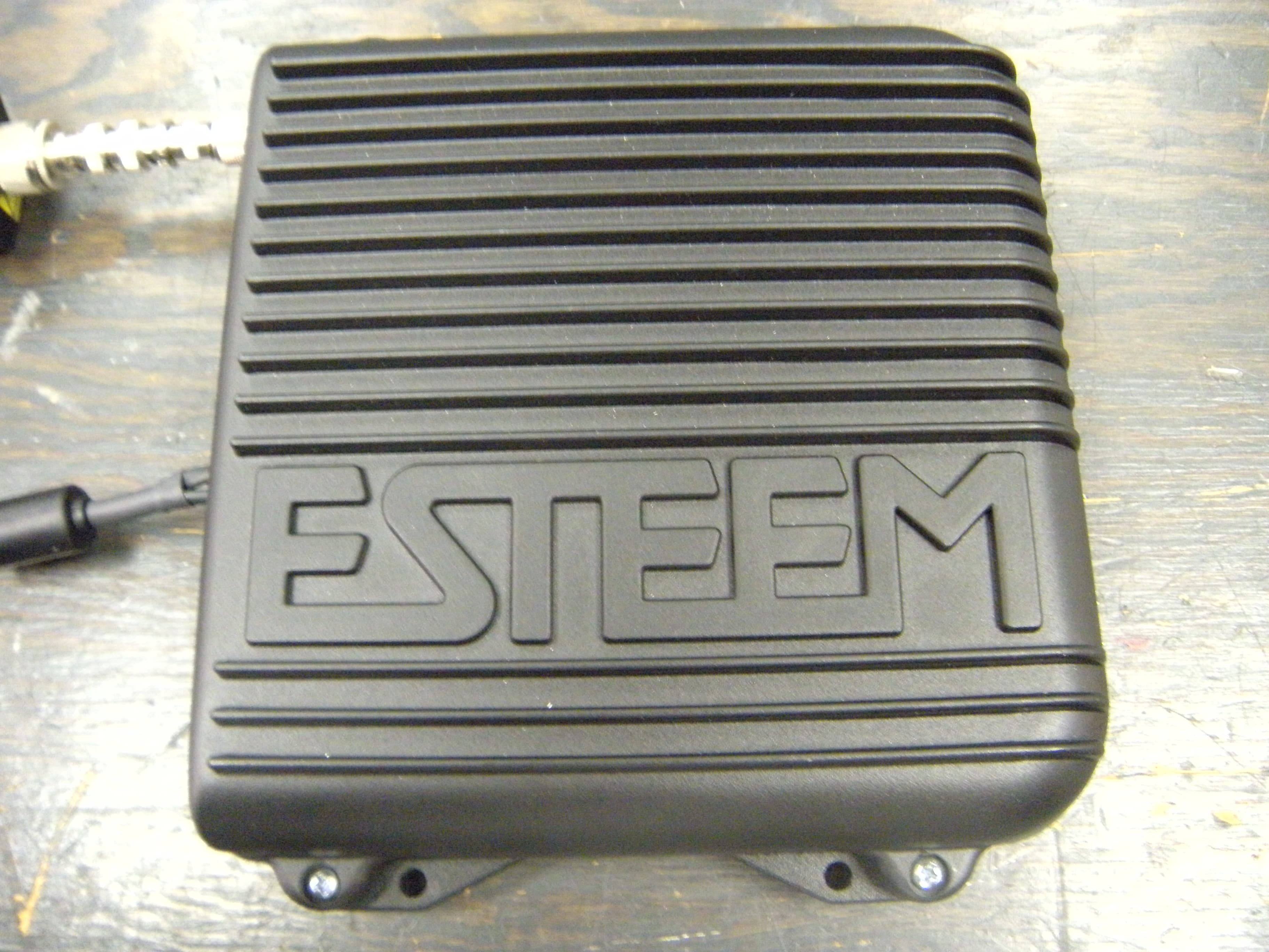
ENPESTEEM210M
Sep 05, 2013Data radio modem
Equipment Class
TNB - Licensed Non-Broadcast Station Transmitter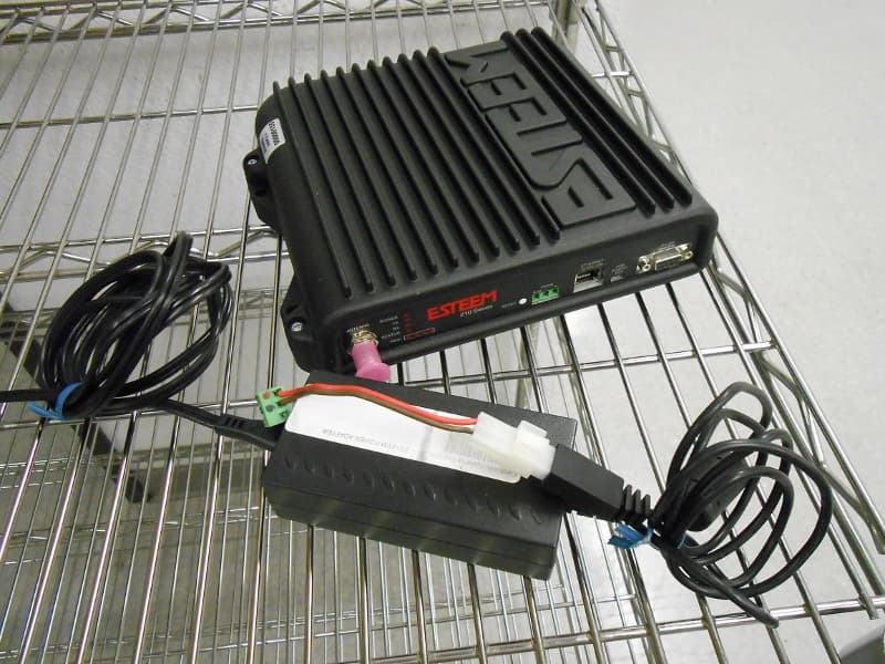
ENPESTEEM210C
Mar 10, 2013Data radio modem
Equipment Class
TNB - Licensed Non-Broadcast Station Transmitter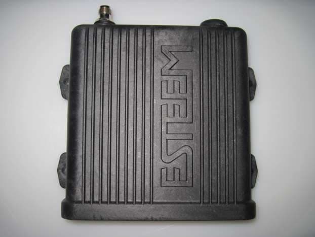
ENPESTEEM195EA
Feb 12, 2012Wireless LAN transceiver
Equipment Class
DTS - Digital Transmission System
ENPESTEEM195ED-1
Mar 23, 2011Wireless LAN transceiver
Equipment Class
DTS - Digital Transmission System