ENPESTEEM192E
Electronic Systems Technology
Click to zoom
Application Details
- Equipment Class
- DSS - Part 15 Spread Spectrum Transmitter
- Date of Grant
- Jan 07, 2003
- Application Purpose
- Original Equipment
- Date of Application
- Aug 02, 2001
- Frequency Range
- 2412.00000000 - 2462.00000000
- Country
- United States
Documents & Files
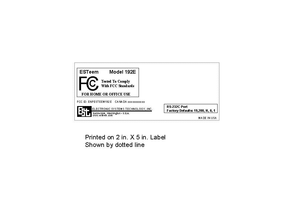
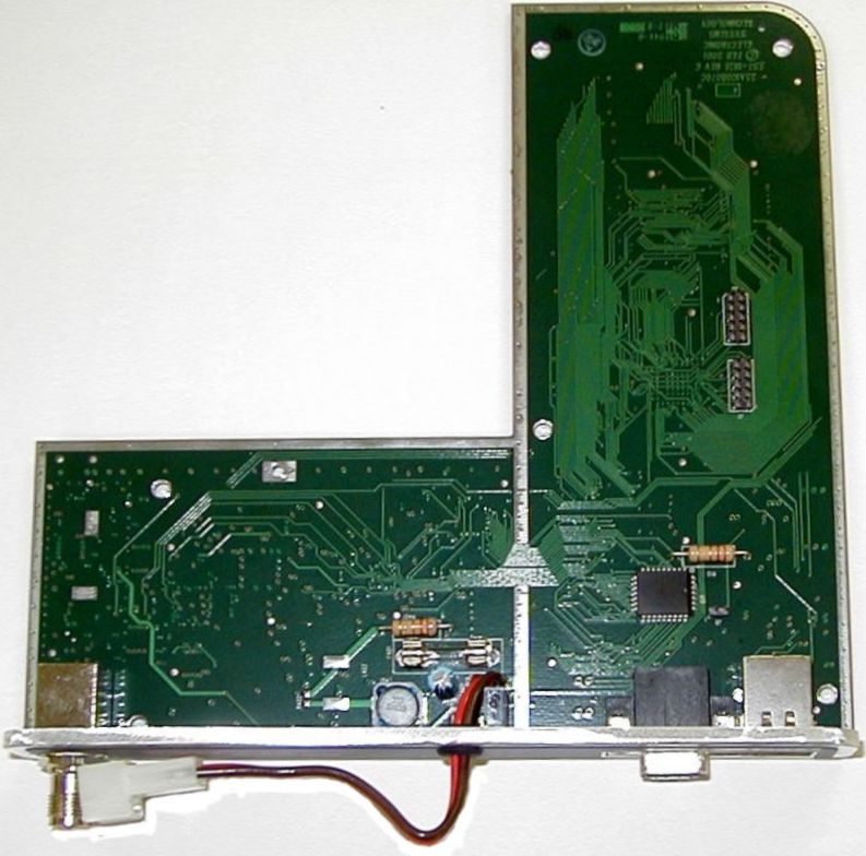
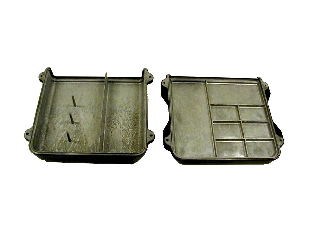
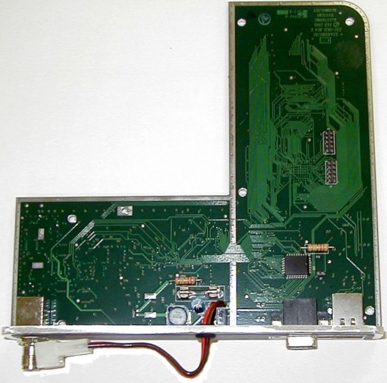
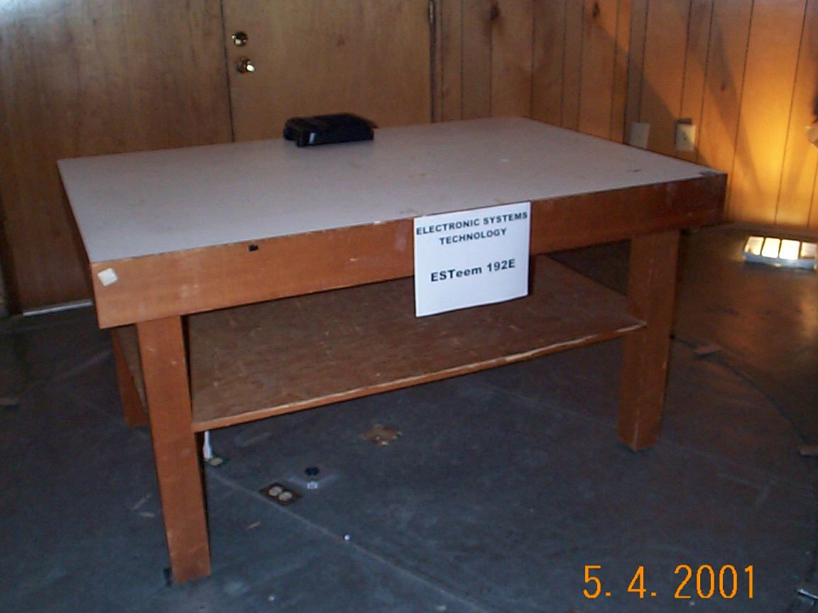
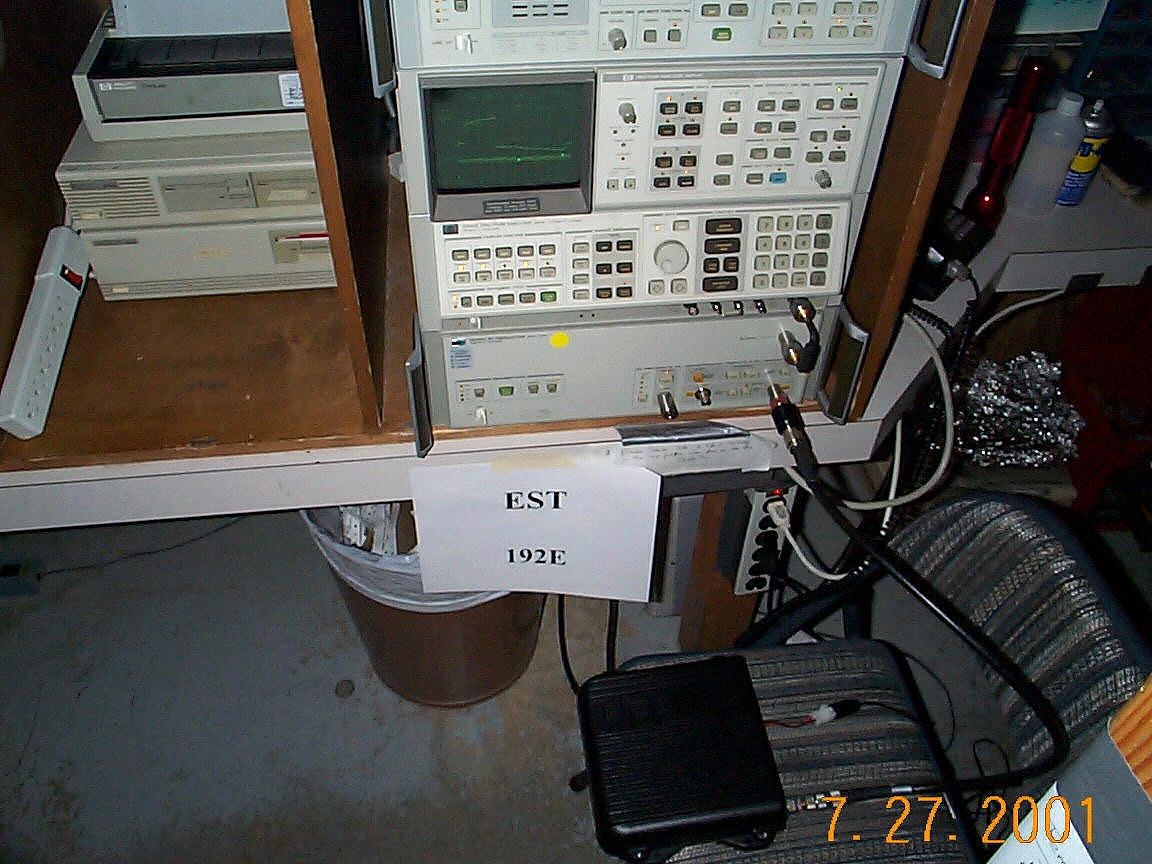
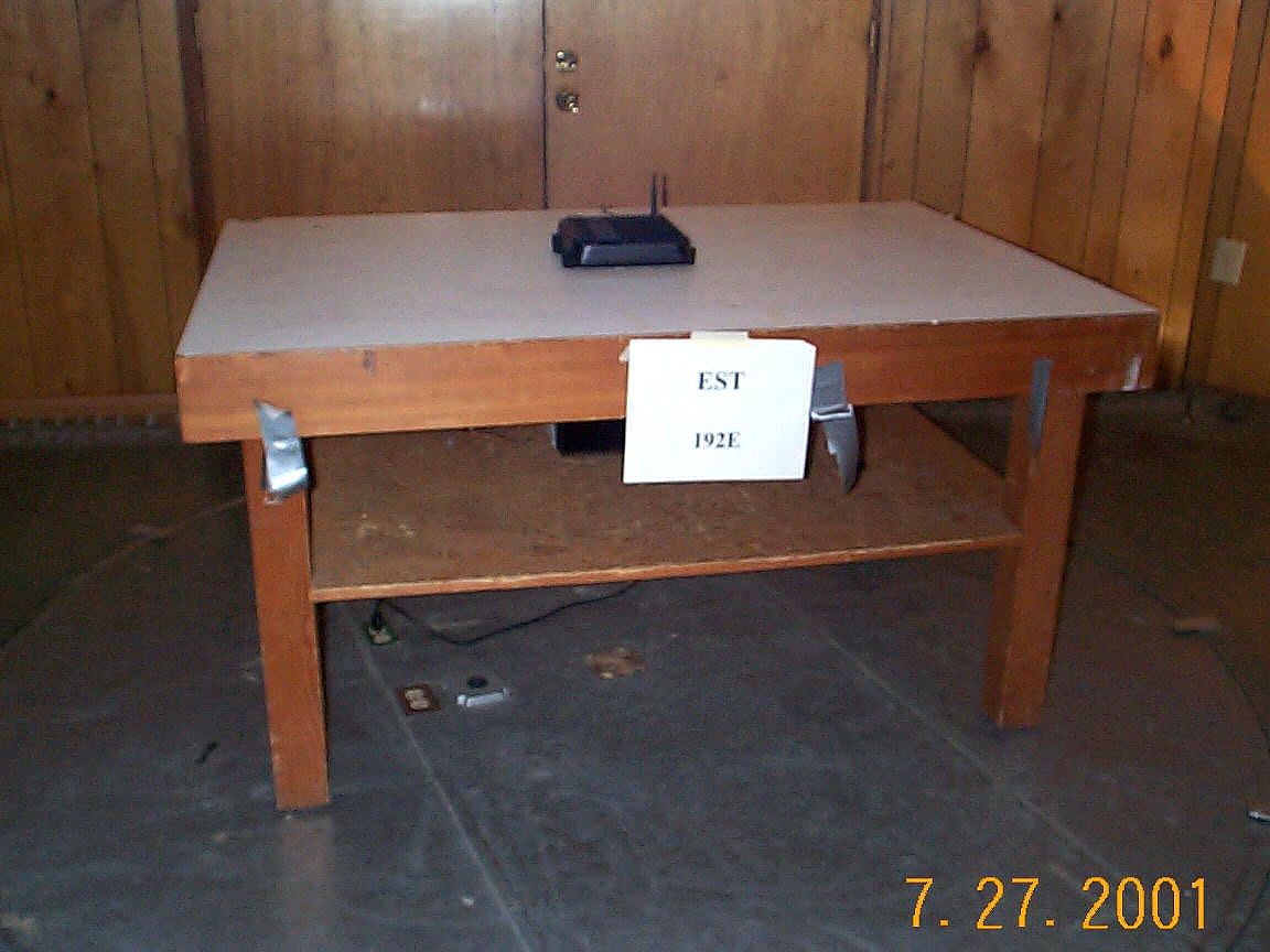
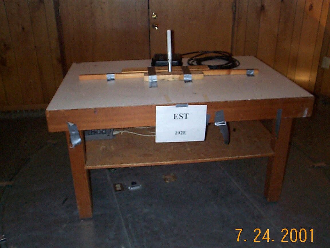
Document Text
Text extracted from the exhibit documents filed with the FCC. Open a document above to read the original.
Users Manual
Revision: 1.0Date: 9 May 01 Electronic Systems Technology (EST) copyrights this manual and the firmware described in it, with all rights reserved. Under the copyright laws, this manual or the firmware internal to the ESTeem unit may not be copied, in whole or part, without the written consent of EST. Under the law, copying includes translating into another language. EST cannot guarantee that you will receive notice of a revision to the firmware described in the manual, even if you have returned a registration/warranty card received with the product. You should periodically check with your authorized EST dealer or call factory direct. EST and the EST logo are registered trademarks of Electronic Systems Technology, Inc. Simultaneously published in the United States and Canada. All rights reserved. ESTEEM USERS MANUAL for MODEL 192E May 2001 Revised: 9 May 01 PRODUCT WARRANTY Electronic Systems Technology, Inc., (hereinafter EST) expressly warrants its products as free of manufacturing defects for a period of one year from the date of sale to first user/customer. THERE ARE NO OTHER WARRANTIES, EXPRESS OR IMPLIED AND THERE IS EXPRESSLY EXCLUDED ALL WARRANTIES OF MERCHANTABILITY OR FITNESS FOR A PARTICULAR PURPOSE. NO OTHER WARRANTY GIVEN BY ANY EMPLOYEE, AGENT, DISTRIBUTOR OR OTHER PERSON WITH RESPECT TO THE PRODUCT SHALL BE BINDING ON EST. LIMITATION OF LIABILITY: EST's liability shall be limited to refunding of purchase price, repair or replacement of product. IN NO EVENT SHALL EST HAVE LIABILITY FOR CONSEQUENTIAL, INCIDENTAL, SPECIAL OR EXEMPLARY DAMAGES CAUSED DIRECTLY OR INDIRECTLY BY THE PRODUCT, INCLUDING BUT NOT LIMITED TO ANY INTERRUPTION OF SERVICES, LOSS OF BUSINESS OR ANTICIPATORY PROFITS. IN NO EVENT SHALL EST BE LIABLE FOR ANY DAMAGES WHATSOEVER IN EXCESS OF THE PURCHASE PRICE OF THE PRODUCT. In the event that a unit or part requires replacement or factory servicing, the following conditions apply: a) Customer must obtain from EST an authorized RMA (Return Materials Authorization) number (call 509-735-9092 Customer Support) before shipment of product or parts to EST for any reason; b) If the whole unit is shipped, it must be in its original carton and shipping components, or a carton and shipping components supplied by EST, or if parts only are shipped, they must be packaged and cushioned so as to prevent damage in transit and shipped freight prepaid; PRODUCT WILL BE CONSIDERED OUT OF WARRANTY IF: a) If the product is damaged due to improper or abnormal use, abuse, mishandling, accident or improper maintenance or failure to follow operating instruction; b) If the product is defective as a result of sand, dirt, or water damage; c)If any factory-sealed enclosure has been opened or shows evidence of an attempt to be opened; d) If defects or damage are caused by the use of unauthorized parts or unauthorized service; e)If the product has had its serial numbers altered or removed. Warranty repair form must be accompanied by proof of user's purchase of unit. Product must be shipped to the manufacturer at the following address: Electronic Systems Technology 415 North Quay Street Kennewick, Washington USA 99336 ADDITIONAL SERVICE: If EST releases an improvement update to firmware internal to the ESTeem unit during the 90 day period after the unit was purchased by the first user/customer, EST will update the applicable unit with the revised version at no charge other than for UPS handling and shipping to and from your location to the EST factory. Return of any such item must be accompanied with proof of purchase. TABLE OF CONTENTS Revised: 9 May 01 CHAPTER 1 - STARTING OUT Overview ............................................................. 1-2 Hardware Layout ................................................. 1-2 Installing ESTeem Utility Software – Windows 95/98/NT ............................................. 1-2 Running The Program ......................................... 1-2 Front Panel Description ....................................... 1-2 Configuration ...................................................... 1-3 Connect and Power Up the ESTeem .................... 1-3 Associate an IP Address with the ESTeem ........... 1-3 Using a DHCP Server .......................................... 1-3 Using the arp Command ...................................... 1-3 CHAPTER 2 – APPLICATION PROGRAMMING System Configurations......................................... 2-2 Access Point Configuration.................................. 2-2 Ethernet Bridge Configuration............................. 2-2 Combined Access Point and Ethernet Bridge ....... 2-2 CHAPTER 3 - INTERFACING Serial Interface Configuration.............................. 3-2 RS-232 Port Pin-Out Table.................................. 3-2 Ethernet Interface ................................................ 3-3 CHAPTER 4 - ANTENNAS Antenna and Cable Configurations.......................4-2 Weather Proofing Coaxial Connectors..................4-2 Grounding ...........................................................4-3 Lightning Arrestors..............................................4-3 Model 192E Typical Outdoor Antenna Installation Diagram ............................................4-3 Model 192E Typical Indoor Antenna Installation Diagram ............................................4-4 ESTeem SWR Measurements Block Diagram ......4-5 APPENDICES Appendix A - FCC Licensing (USA only)................................................ APX A-2 Appendix B - Specifications ESTeem Specifications................................APX B-1 Model 192E Antenna Specifications............APX B-2 CHAPTER 2 APPLICATION PROGRAMMING SYSTEM CONFIGURATIONS ACCESS POINT CONFIGURATION ETHERNET BRIDGING CONFIGURATION COMBINED ACCESS POINT AND ETHERNET BRIDGING CONFIGURATION Ethernet Wired LAN Mobile Wireless Network With Overlap Coverage 192E Model WLANC11 Wireless LAN Card 192E Point to Multi-Point Wireless Network 192E Ethernet Wired LAN Wireless Access Point Prog…
Text truncated - open the document above for the full version.
Users Manual
Revision: 1.0Date: 7 Sep 01 Electronic Systems Technology (EST) copyrights this manual and the firmware described in it, with all rights reserved. Under the copyright laws, this manual or the firmware internal to the ESTeem unit may not be copied, in whole or part, without the written consent of EST. Under the law, copying includes translating into another language. EST cannot guarantee that you will receive notice of a revision to the firmware described in the manual, even if you have returned a registration/warranty card received with the product. You should periodically check with your authorized EST dealer or call factory direct. EST and the EST logo are registered trademarks of Electronic Systems Technology, Inc. Simultaneously published in the United States and Canada. All rights reserved. ESTEEM USERS MANUAL for MODEL 192E May 2001 Revised: 27 Sep 01 PRODUCT WARRANTY Electronic Systems Technology, Inc., (hereinafter EST) expressly warrants its products as free of manufacturing defects for a period of one year from the date of sale to first user/customer. THERE ARE NO OTHER WARRANTIES, EXPRESS OR IMPLIED AND THERE IS EXPRESSLY EXCLUDED ALL WARRANTIES OF MERCHANTABILITY OR FITNESS FOR A PARTICULAR PURPOSE. NO OTHER WARRANTY GIVEN BY ANY EMPLOYEE, AGENT, DISTRIBUTOR OR OTHER PERSON WITH RESPECT TO THE PRODUCT SHALL BE BINDING ON EST. LIMITATION OF LIABILITY: EST's liability shall be limited to refunding of purchase price, repair or replacement of product. IN NO EVENT SHALL EST HAVE LIABILITY FOR CONSEQUENTIAL, INCIDENTAL, SPECIAL OR EXEMPLARY DAMAGES CAUSED DIRECTLY OR INDIRECTLY BY THE PRODUCT, INCLUDING BUT NOT LIMITED TO ANY INTERRUPTION OF SERVICES, LOSS OF BUSINESS OR ANTICIPATORY PROFITS. IN NO EVENT SHALL EST BE LIABLE FOR ANY DAMAGES WHATSOEVER IN EXCESS OF THE PURCHASE PRICE OF THE PRODUCT. In the event that a unit or part requires replacement or factory servicing, the following conditions apply: a)Customer must obtain from EST an authorized RMA (Return Materials Authorization) number (call 509-735-9092 Customer Support) before shipment of product or parts to EST for any reason; b)If the whole unit is shipped, it must be in its original carton and shipping components, or a carton and shipping components supplied by EST, or if parts only are shipped, they must be packaged and cushioned so as to prevent damage in transit and shipped freight prepaid; PRODUCT WILL BE CONSIDERED OUT OF WARRANTY IF: a)If the product is damaged due to improper or abnormal use, abuse, mishandling, accident or improper maintenance or failure to follow operating instruction; b)If the product is defective as a result of sand, dirt, or water damage; c)If any factory-sealed enclosure has been opened or shows evidence of an attempt to be opened; d)If defects or damage are caused by the use of unauthorized parts or unauthorized service; e)If the product has had its serial numbers altered or removed. Warranty repair form must be accompanied by proof of user's purchase of unit. Product must be shipped to the manufacturer at the following address: Electronic Systems Technology 415 North Quay Street Kennewick, Washington USA 99336 ADDITIONAL SERVICE: If EST releases an improvement update to firmware internal to the ESTeem unit during the 90 day period after the unit was purchased by the first user/customer, EST will update the applicable unit with the revised version at no charge other than for UPS handling and shipping to and from your location to the EST factory. Return of any such item must be accompanied with proof of purchase. TABLE OF CONTENTS Revised: 27 Sep 01 CHAPTER 1 - STARTING OUT Overview.............................................................1-2 Hardware Layout.................................................1-2 Installing ESTeem Utility Software – Windows 95/98/NT..............................................1-2 Running The Program.........................................1-2 Front Panel Description.......................................1-3 Basic Configuration.............................................1-3 Connect and Power Up the ESTeem.....................1-3 Opening the ESTeem Configuration Menu..........1-4 CHAPTER 2 – APPLICATION PROGRAMMING Selecting Ethernet Configuration.........................2-2 Using the Configuration Menu.............................2-2 Accessing Through Telnet...................................2-2 Changing Configuration Information...................2-2 Saving and Exiting Configuration Menu..............2-2 Modem Setup.......................................................2-2 Step 1 – Radio Configuration...............................2-2 Step 2 – Modes of Operation................................2-3 Access Point Configuration..................................2-3 Ethernet Bridging Configuration.........................2-4 Master Bridge......................................................2-5 Client Bridge.......................................................2-5 Repeater Configuration.......................................2-6 Combined Access Point and Bridging..................2-6 Loading Factory Default Values..........................2-7 CHAPTER 3 - INTERFACING Serial Interface Configuration.............................3-2 RS-232 Port Pin-Out Table..................................3-2 Ethernet Interface................................................3-3 CHAPTER 4 - ANTENNAS Antenna and Cable Configurations......................4-2 Weather Proofing Coaxial Connectors.................4-2 Grounding...........................................................4-3 Lightning Arrestors.............................................4-3 Model 192E Typical Outdoor Antenna Installation Diagram...........................................4-3 Model 192E Typical Indoor Antenna Installation Diagram...........................................4-4 ESTeem SWR Measurements Block Diagram.....4-5 APPENDICES Appendix A - FCC Licensing (USA only).............................................…
Text truncated - open the document above for the full version.
Users Manual
Revision: 1.1Date: 15 Oct 01 Electronic Systems Technology (EST) copyrights this manual and the firmware described in it, with all rights reserved. Under the copyright laws, this manual or the firmware internal to the ESTeem unit may not be copied, in whole or part, without the written consent of EST. Under the law, copying includes translating into another language. EST cannot guarantee that you will receive notice of a revision to the firmware described in the manual, even if you have returned a registration/warranty card received with the product. You should periodically check with your authorized EST dealer or call factory direct. EST and the EST logo are registered trademarks of Electronic Systems Technology, Inc. Simultaneously published in the United States and Canada. All rights reserved. ESTEEM USERS MANUAL for MODEL 192E October 2001 Revised: 15 Oct 01 PRODUCT WARRANTY Electronic Systems Technology, Inc., (hereinafter EST) expressly warrants its products as free of manufacturing defects for a period of one year from the date of sale to first user/customer. THERE ARE NO OTHER WARRANTIES, EXPRESS OR IMPLIED AND THERE IS EXPRESSLY EXCLUDED ALL WARRANTIES OF MERCHANTABILITY OR FITNESS FOR A PARTICULAR PURPOSE. NO OTHER WARRANTY GIVEN BY ANY EMPLOYEE, AGENT, DISTRIBUTOR OR OTHER PERSON WITH RESPECT TO THE PRODUCT SHALL BE BINDING ON EST. LIMITATION OF LIABILITY: EST's liability shall be limited to refunding of purchase price, repair or replacement of product. IN NO EVENT SHALL EST HAVE LIABILITY FOR CONSEQUENTIAL, INCIDENTAL, SPECIAL OR EXEMPLARY DAMAGES CAUSED DIRECTLY OR INDIRECTLY BY THE PRODUCT, INCLUDING BUT NOT LIMITED TO ANY INTERRUPTION OF SERVICES, LOSS OF BUSINESS OR ANTICIPATORY PROFITS. IN NO EVENT SHALL EST BE LIABLE FOR ANY DAMAGES WHATSOEVER IN EXCESS OF THE PURCHASE PRICE OF THE PRODUCT. In the event that a unit or part requires replacement or factory servicing, the following conditions apply: a)Customer must obtain from EST an authorized RMA (Return Materials Authorization) number (call 509-735-9092 Customer Support) before shipment of product or parts to EST for any reason; b)If the whole unit is shipped, it must be in its original carton and shipping components, or a carton and shipping components supplied by EST, or if parts only are shipped, they must be packaged and cushioned so as to prevent damage in transit and shipped freight prepaid; PRODUCT WILL BE CONSIDERED OUT OF WARRANTY IF: a)If the product is damaged due to improper or abnormal use, abuse, mishandling, accident or improper maintenance or failure to follow operating instruction; b)If the product is defective as a result of sand, dirt, or water damage; c)If any factory-sealed enclosure has been opened or shows evidence of an attempt to be opened; d)If defects or damage are caused by the use of unauthorized parts or unauthorized service; e)If the product has had its serial numbers altered or removed. Warranty repair form must be accompanied by proof of user's purchase of unit. Product must be shipped to the manufacturer at the following address: Electronic Systems Technology 415 North Quay Street Kennewick, Washington USA 99336 ADDITIONAL SERVICE: If EST releases an improvement update to firmware internal to the ESTeem unit during the 90 day period after the unit was purchased by the first user/customer, EST will update the applicable unit with the revised version at no charge other than for UPS handling and shipping to and from your location to the EST factory. Return of any such item must be accompanied with proof of purchase. TABLE OF CONTENTS Revised: 15 Oct 01 CHAPTER 1 - STARTING OUT Overview.............................................................1-2 Hardware Layout.................................................1-2 Installing ESTeem Utility Software – Windows 95/98/NT..............................................1-2 Running The Program.........................................1-2 Front Panel Description.......................................1-3 Basic Configuration.............................................1-3 Connect and Power Up the ESTeem.....................1-3 Opening the ESTeem Configuration Menu..........1-4 CHAPTER 2 – APPLICATION PROGRAMMING Selecting Ethernet Configuration.........................2-2 Using the Configuration Menu.............................2-2 Accessing Through Telnet...................................2-2 Changing Configuration Information...................2-2 Saving and Exiting Configuration Menu..............2-2 Modem Setup.......................................................2-2 Step 1 – Radio Configuration...............................2-2 Step 2 – Modes of Operation................................2-3 Access Point Configuration..................................2-3 Ethernet Bridging Configuration.........................2-4 Master Bridge......................................................2-5 Client Bridge.......................................................2-5 Repeater Configuration.......................................2-6 Combined Access Point and Bridging..................2-6 Loading Factory Default Values..........................2-7 CHAPTER 3 - INTERFACING Serial Interface Configuration.............................3-2 RS-232 Port Pin-Out Table..................................3-2 Ethernet Interface................................................3-3 CHAPTER 4 - ANTENNAS Antenna and Cable Configurations......................4-2 Weather Proofing Coaxial Connectors.................4-2 Grounding...........................................................4-3 Lightning Arrestors.............................................4-3 Model 192E Typical Outdoor Antenna Installation Diagram...........................................4-3 Model 192E Typical Indoor Antenna Installation Diagram...........................................4-4 ESTeem SWR Measurements Block Diagram.....4-5 APPENDICES Appendix A - FCC Licensing (USA only)........................................…
Text truncated - open the document above for the full version.
Operational Description
Revised: 30 Jul 01 1 of 10 www.esteem.com PROCEDURE 01-001 ELECTRONIC SYSTEMS TECHNOLOGY 509-735-9092 (O) 415 N. QUAY STREET KENNEWICK, WA 99336 509-783-5475 (FAX) Date:July 17, 2001 Subject :FCC 15.247(e) Jamming Margin Test on the ESTeem Model 192E Tools Required :See equipment list in the report. Parts Required :2 ea. ESTeem Model 192E Scope: This report presents the test procedure, test configuration and test data associated with FCC Part 15.247 (e) Jamming Margin test for indirect measurement of processing gain. Test Background and Procedure According to FCC regulations 15.247 (e) , a direct sequence spread spectrum system must have a processing gain, of at least 10 dB. Compliance to this requirement can be shown by demonstrating a bit error ratio (BER) performance improvement between the spread spectrum processes (coding, modulation) are engaged relative to the processes being bypassed. The ESTeem 192E process gain can not be bypassed. The processing gain can be indirectly measured by the Jamming Margin test described in FCC 15.247 (e)2 Test Procedure Setup the simplex hardware link as shown in Figure 1. Perform all independent instrumentation calibrations prior to starting test. Set operational power levels using fixed and variable attenuators in the system to meet the following objectives: 1. Adjust signal power at receiver to approximately –60 dBm. Use the spectrum analyzer to verify. 2. Ensure that the CW Jammer generator RF output is disabled and measure the Model 192E RF power with the power meter. This measurement will be the relative signal power level. 3. Disable the Model 192E transmitter, and set CW Jammer generator RF output frequency equal to the carrier frequency and enable generator output. Set the CW Jammer reference power level at the power meter to 8.4 dB (for 11 Mbps) or 2.6 dB (for 2 Mbps) below the level of the Model 192E relative measurement measured in step 2. This will set the relative Signal to Jammer ratio, the limit to pass the 10dB processing gain test for a BER of 10 -5. 4. Disable the CW Jammer and reestablish the communications link between Model 192E units 1 and 2. 5. Enable CW Jammer at a low power level and gradually increase the CW Jammer output power until the BER test indicates the reference BER level is 10 -5 . 6. Step the CW Jammer 50 KHz then increase the output power level until the BER is equal to the reference BER. Record the Jammer power level. 7. Repeat step until the all of the receiver passband has been tested. Reference Figure 2. This technique is used for a fixed signal carrier frequency with uniform frequency increments of 50 KHz across the receiver passband using the CW Jammer. In this case the receiver bandpass is ± 8.5 MHz. Revised: 30 Jul 01 2 of 10 www.esteem.com PROCEDURE 01-001 ELECTRONIC SYSTEMS TECHNOLOGY 509-735-9092 (O) 415 N. QUAY STREET KENNEWICK, WA 99336 509-783-5475 (FAX) The processing gain is related to the jamming margin as follows: G p = BER REFERENCE ↔ (S/N) OUTPUT + (J/S) + L system BER reference is the reference bit error ratio with its corresponding theoretical output signal noise ratio per symbol, (S/N) output. (J/S) is the jamming margin (jamming signal power relative to desired signal power) L system is the system implementation losses. The ESTeem 192E utilizes the Intersil PRISM HFA3863 base band processor. The bit rates are 1, 2, 5.5, and 11 Mbps. The corresponding symbol rates are 1, 1, 1.375, and 1.375 MSps. The chip rate is always 11 MCps, so the ratio of chip rate to symbol rate is 11:1 for the 1 and 2 Mbps rates and 8:1 for the 5.5 and 11 Mbps rates [1]. For the 1 and 2 Mbps modes, the transmitter accepts data, scrambles it, differentially encodes it as either DBPSK or DQPSK and spreads it with the BPSK PN sequence. [2]. This means that for every error that occurs the differential decoding extends that to 2 errors. Thus, you can expect the theoretical BPSK 9.6 dB Es/No performance for BER of 10 -5 to be degraded to 10.6 dB. [3] The implementation losses of 2 dB are then added for a total of 12.6 dB Gp = (Eb/No) + (J/S) + L system Gp = 10.6 dB + (J/S) + 2 dB Gp = 12.6 dB + (J/S) The minimum processing gain is 10 dB therefore: Gp = 12.6 dB + (J/S) >10dB The minimum jammer to signal ratio for 2 Mbps rate is as follows: (J/S)> -2.6 dB For 5.5 and 11 Mbps modes, the transmitter partitions the data into nibbles (4 bits) or bytes (8 bits). At 5.5 Mbps, it uses two of those bits to select one of 4 complex spread sequences from a table of CCK sequences and then QPSK modulates that symbol with the remaining 2 bits. At 11 Mbps one byte is used of which 6 bits select one of 64 spread sequences for a symbol and the other 2 are used to QPSK modulate that symbol. [2]. There are losses with complementary encoding and scrambling that cause loss in performance due to error extension. Intersil states that the Es/No is 16.4 dB at BER of 10 -5 [1] . The implementation losses of 2 dB are then added for a total of 18.4 dB. Gp = (Eb/No) + (J/S) + L system Gp = 16.4 dB + (J/S) + 2 dB Gp = 18.4 dB + (J/S) The minimum processing gain is 10 dB therefore: Revised: 30 Jul 01 3 of 10 www.esteem.com PROCEDURE 01-001 ELECTRONIC SYSTEMS TECHNOLOGY 509-735-9092 (O) 415 N. QUAY STREET KENNEWICK, WA 99336 509-783-5475 (FAX) Gp = 18.4 dB + (J/S) >10dB The minimum jammer to signal ratio for 11 Mbps rate is as follows: (J/S)> -8.4 dB The Jammer Margin test procedure allows the worst 20% of the J/S points to be discarded. The minimum measured processing is 10 dB. Therefore the 192E complies with the 10 dB minimum processing gain requirement. The graphical data associated with the following radio channels and chip symbol rates is tabulated and presented for: Channel 1: 2412 MHz 2 Mbps Figure 2 Channel 6: 2437 MHz 2 Mbps Figure 3 Channel 11: 2462 MHz 2 Mbps Figure 4 Channel 1: 2412 MHz 11 Mbps Figure 5 Channel 6: 2437 MHz 11 Mbps Figure 6 Channel 11: 2462 MHz 11 Mbps Figure 7 The test equipment used is listed below. EquipmentSerial NumberCal…
Text truncated - open the document above for the full version.
Test Report
Acme Testing Co. 2002 Valley Highway PO Box 3 Acme WA 98220-0003 phone:888 226-3837 fax: 360 595-2722 Document Number: 2001100 Document Date: 02 October 2001 Electronic Systems Technology, ESTeem 192E FCC Rules: 47CFR Part 15 Subpart C (15.247) Page 1 of 43 REPORT OF MEASUREMENTS PART 15C (15.247) – INTENTIONAL RADIATOR DEVICE: WIRELESS MODEM MODEL: ESTeem 192E MANUFACTURER: ELECTRONIC SYSTEMS TECHNOLOGY, INC. ADDRESS: 415 N. QUAY STREET KENNEWICK WA 99336 WORK ORDER: 01-EMC-042503 Acme Testing Co. 2002 Valley Highway PO Box 3 Acme WA 98220-0003 phone:888 226-3837 fax: 360 595-2722 Document Number: 2001100 Document Date: 02 October 2001 Electronic Systems Technology, ESTeem 192E FCC Rules: 47CFR Part 15 Subpart C (15.247) Page 2 of 43 1. GENERAL..................................................................................................................................................................4 1.1 DOCUMENT HISTORY..............................................................................................................................................4 1.2 PURPOSE................................................................................................................................................................5 1.3 MANUFACTURER....................................................................................................................................................5 1.4 TEST LOCATION......................................................................................................................................................5 1.5 ACCREDITATIONS AND LISTINGS.............................................................................................................................5 2. TEST RESULTS SUMMARY....................................................................................................................................6 3. DESCRIPTION OF EQUIPMENT............................................................................................................................7 3.1 EQUIPMENT UNDER TEST (EUT).............................................................................................................................7 3.2 THE MODE OF OPERATION DURING TESTS...............................................................................................................7 3.3 MODIFICATIONS REQUIRED FOR EMISSIONS COMPLIANCE.........................................................................................7 3.4 SUPPORT EQUIPMENT USED DURING TESTING..........................................................................................................7 3.5 DESCRIPTION OF CABLES FOR EMISSIONS.................................................................................................................8 3.6 EUT PHOTOGRAPHS...............................................................................................................................................8 4. ANTENNA REQUIREMENT....................................................................................................................................9 4.1 REGULATION..........................................................................................................................................................9 4.2 TEST RESULTS........................................................................................................................................................9 5. AC POWER LINE CONDUCTED EMISSIONS TESTS........................................................................................10 5.1 TEST EQUIPMENT.................................................................................................................................................10 5.2 PURPOSE..............................................................................................................................................................10 5.3 TEST PROCEDURES...............................................................................................................................................10 5.4 TEST RESULTS......................................................................................................................................................11 5.5 TEST SETUP PHOTOGRAPHS..................................................................................................................................13 6. 6 DB BANDWIDTH.................................................................................................................................................14 6.1 REGULATION........................................................................................................................................................14 6.2 TEST EQUIPMENT.................................................................................................................................................14 6.3 TEST PROCEDURES...............................................................................................................................................14 6.4 TEST RESULTS......................................................................................................................................................14 6.5 TEST SETUP PHOTOGRAPHS..................................................................................................................................17 7. POWER OUTPUT....................................................................................................................................................18 7.1 REGULATION........................................................................................................................................................18 7.2 TEST EQUIPMENT.................................................................................................................................................18 7.3 TEST PROCEDURES...................................................…
Text truncated - open the document above for the full version.
Contact Information
Applicant
Todd Elliott(Engineer)
Technical Contact
Acme TestingHarry H Hodes
[email protected]360 595-2785
2002 Valley Highway · Acme, Washington · United States
Non-Technical Contact
Acme TestingDesiree R Patterson
[email protected]360 595-2785
Test Firm
Acme Testing Co.Harry Hodes
Technical Specifications
| # | Rule Parts | Frequency Range | Power Output |
|---|---|---|---|
| 1 | 15C | 2.41 GHz - 2.46 GHz | 547.00 mW |
Other Applications from Electronic Systems Technology
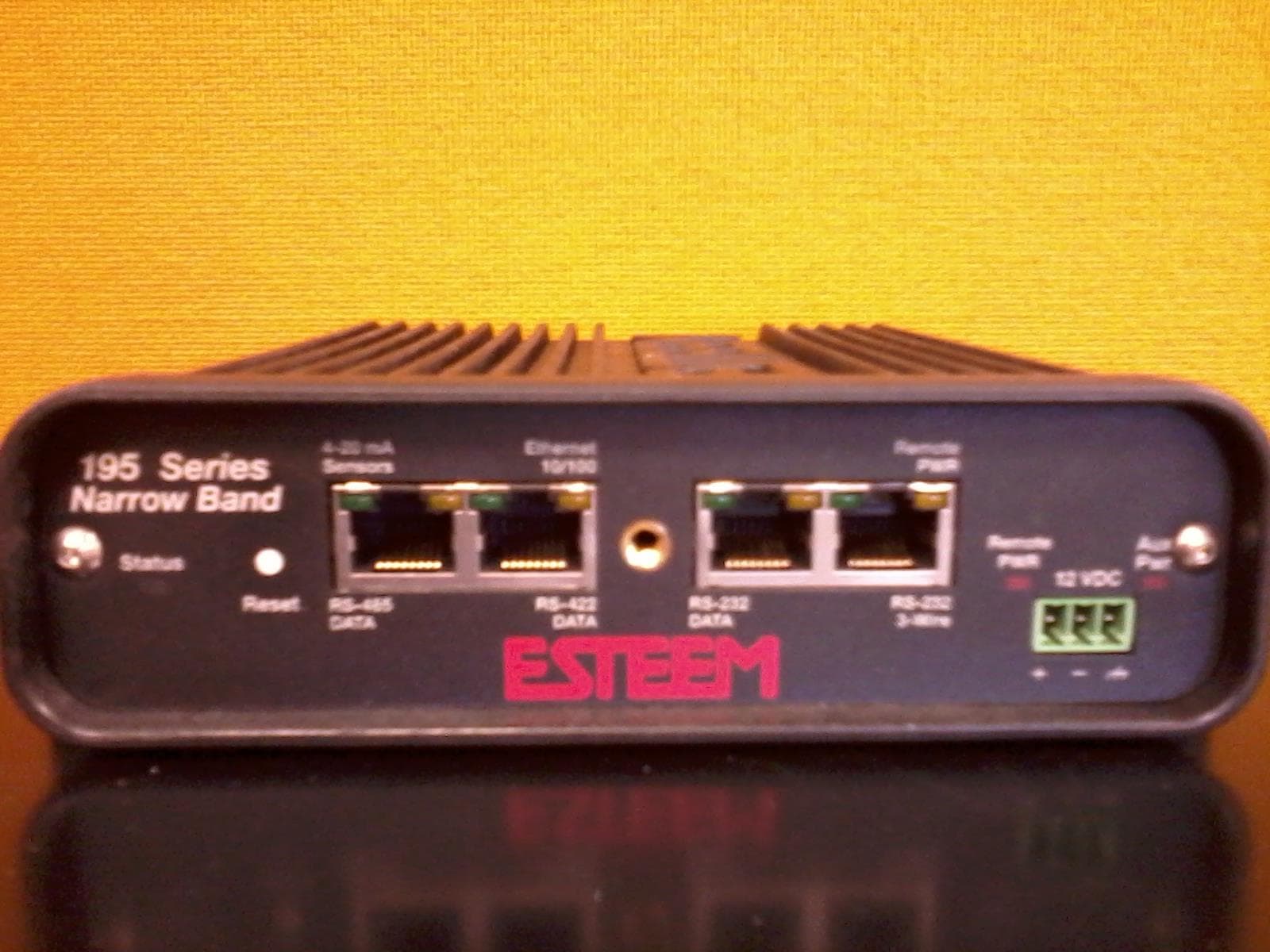
ENPESTEEM195H
Aug 12, 2014217-220MHz VHF Telemetry Modem
Equipment Class
TNB - Licensed Non-Broadcast Station Transmitter
ENPESTEEM195C
Dec 19, 2013450-470MHz Narrow-band UHF modem
Equipment Class
TNB - Licensed Non-Broadcast Station Transmitter
ENPESTEEM210M
Sep 05, 2013Data radio modem
Equipment Class
TNB - Licensed Non-Broadcast Station Transmitter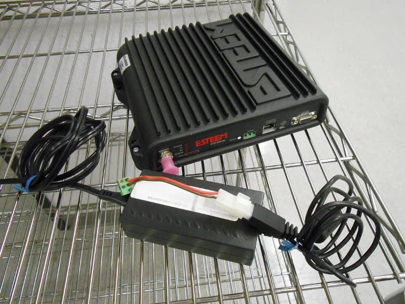
ENPESTEEM210C
Mar 10, 2013Data radio modem
Equipment Class
TNB - Licensed Non-Broadcast Station Transmitter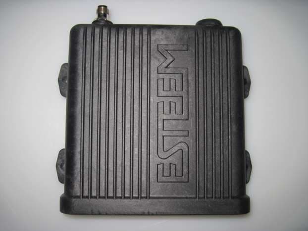
ENPESTEEM195EA
Feb 12, 2012Wireless LAN transceiver
Equipment Class
DTS - Digital Transmission System