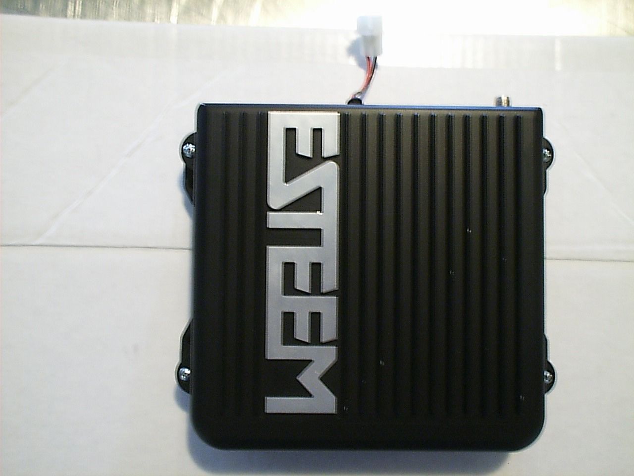
ENPESTEEM192SWireless Modem
Electronic Systems Technology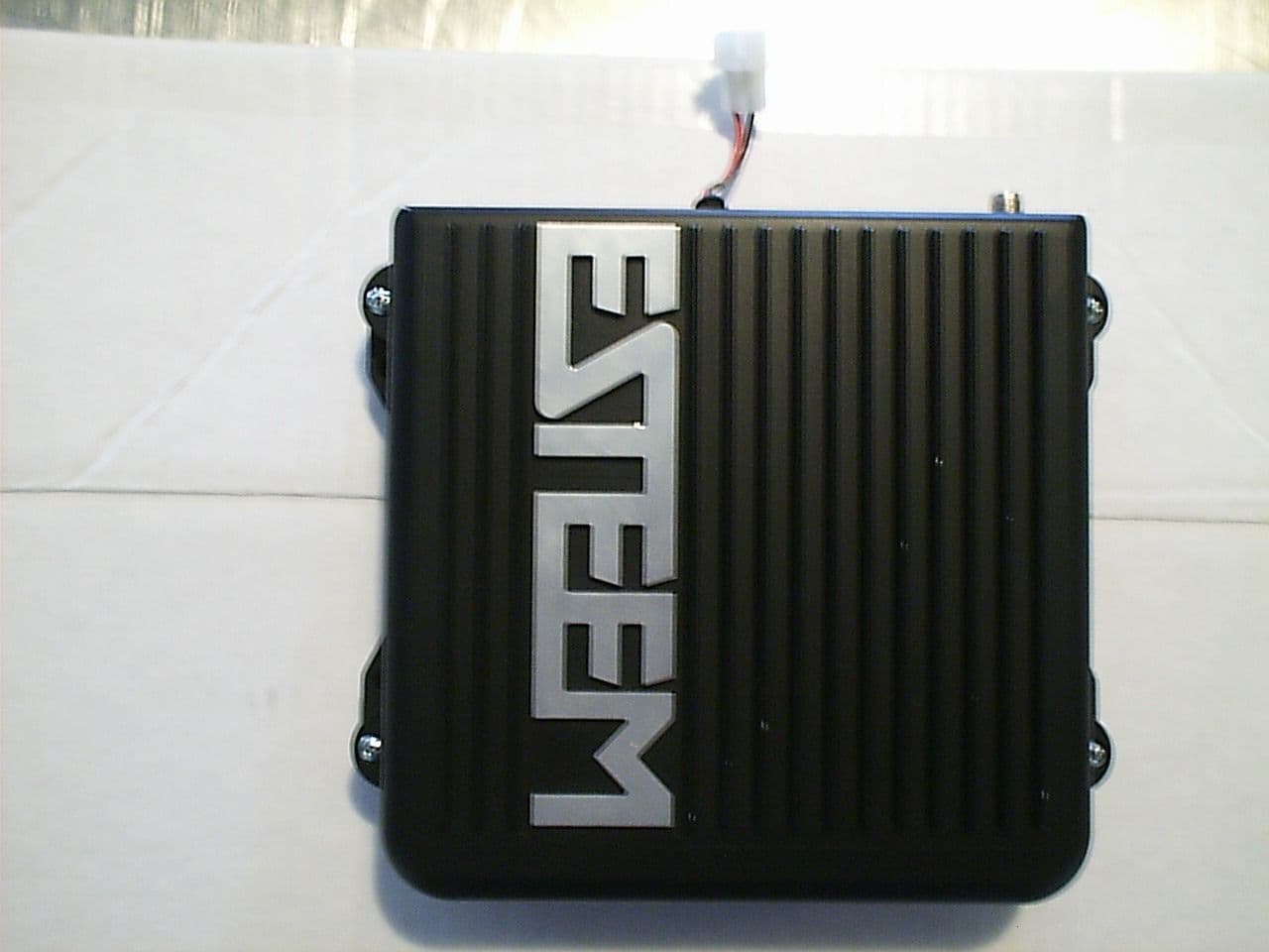
Click to zoom
Application Details
- Equipment Class
- DSS - Part 15 Spread Spectrum Transmitter
- Date of Grant
- May 13, 1999
- Application Purpose
- Original Equipment
- Date of Application
- Mar 25, 1999
- Equipment Note
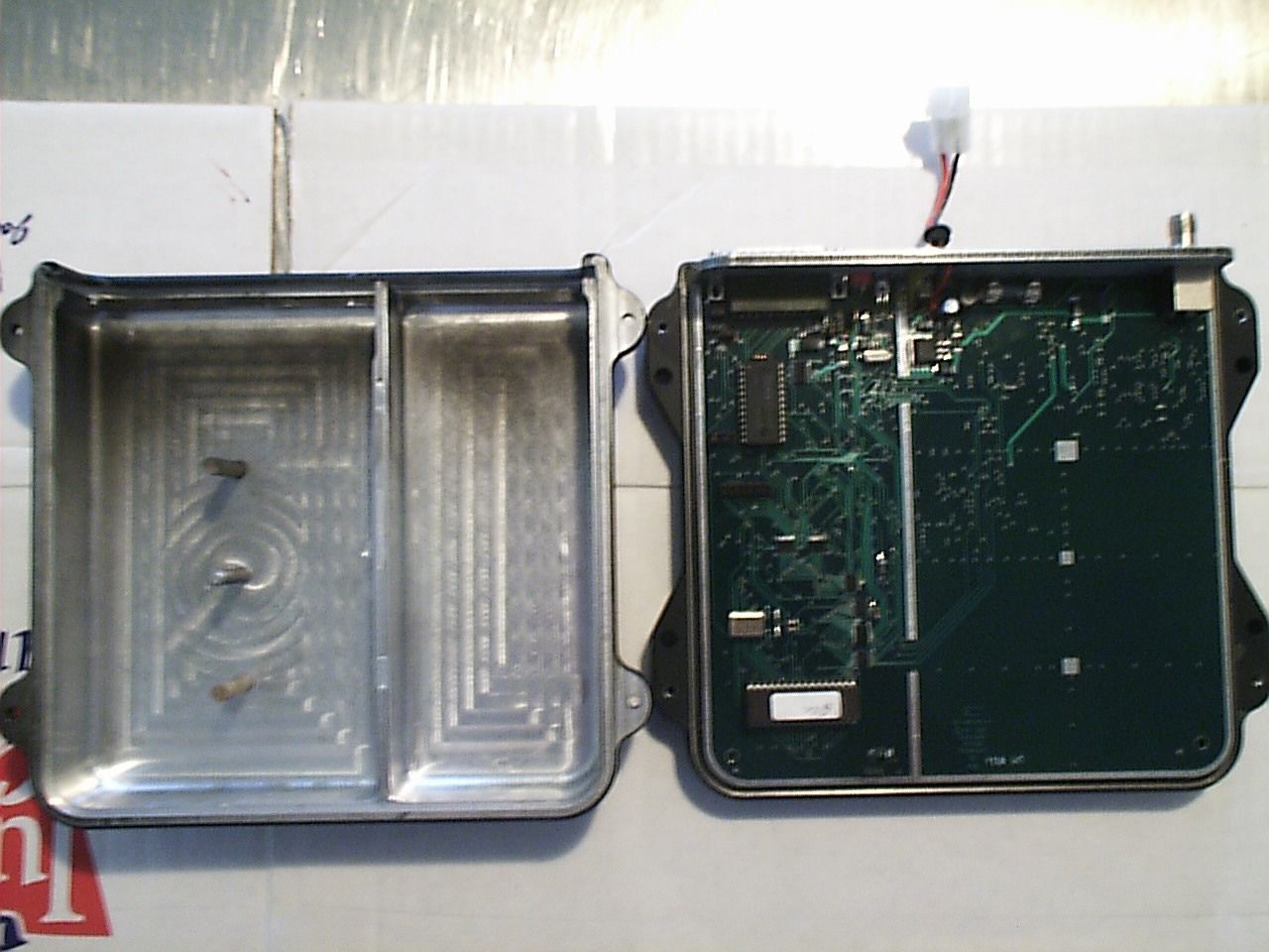
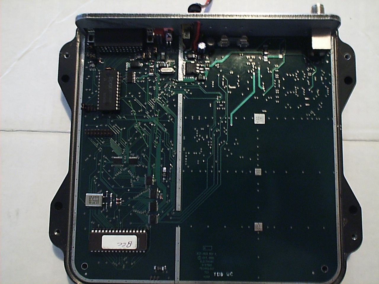
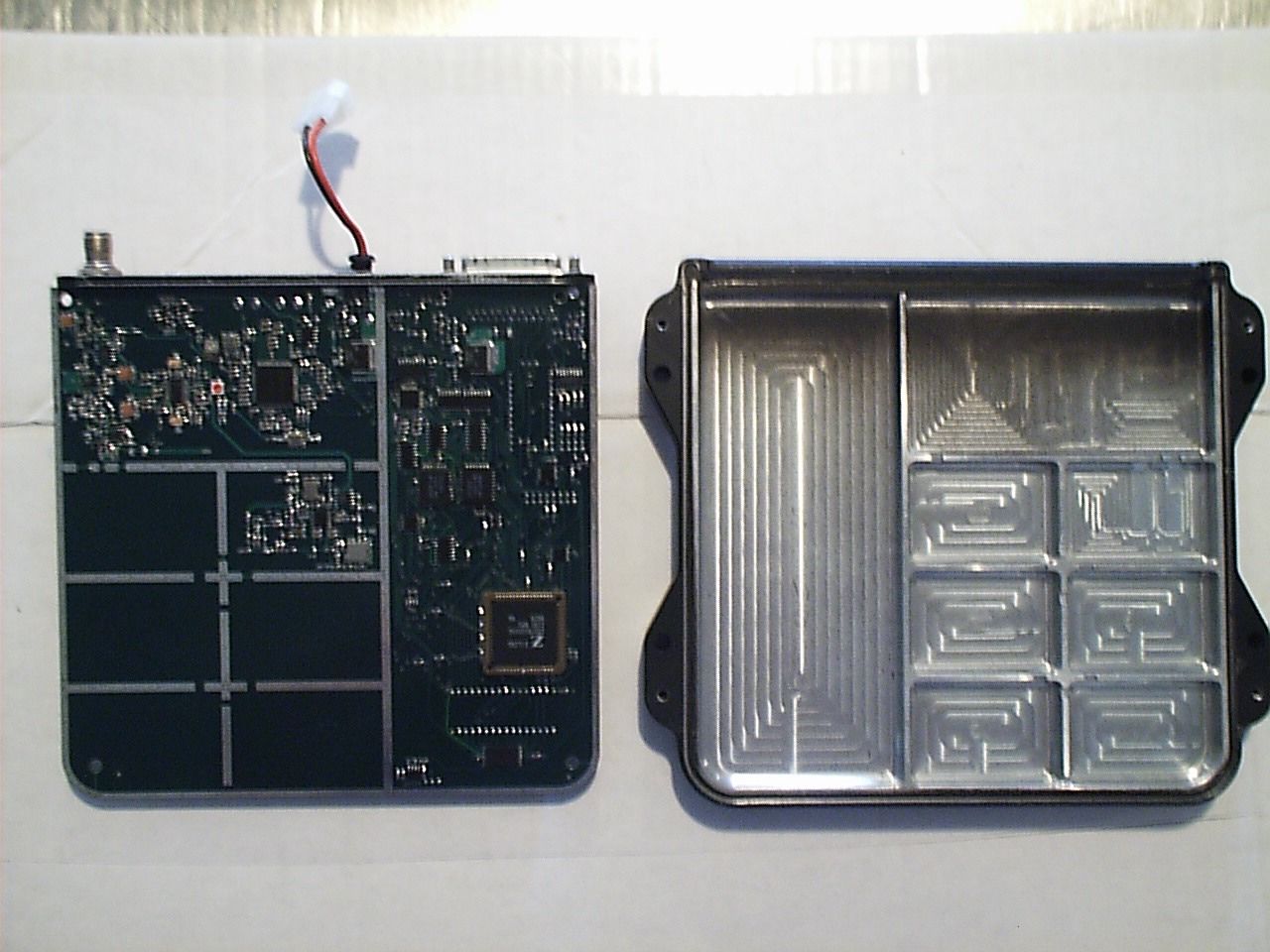
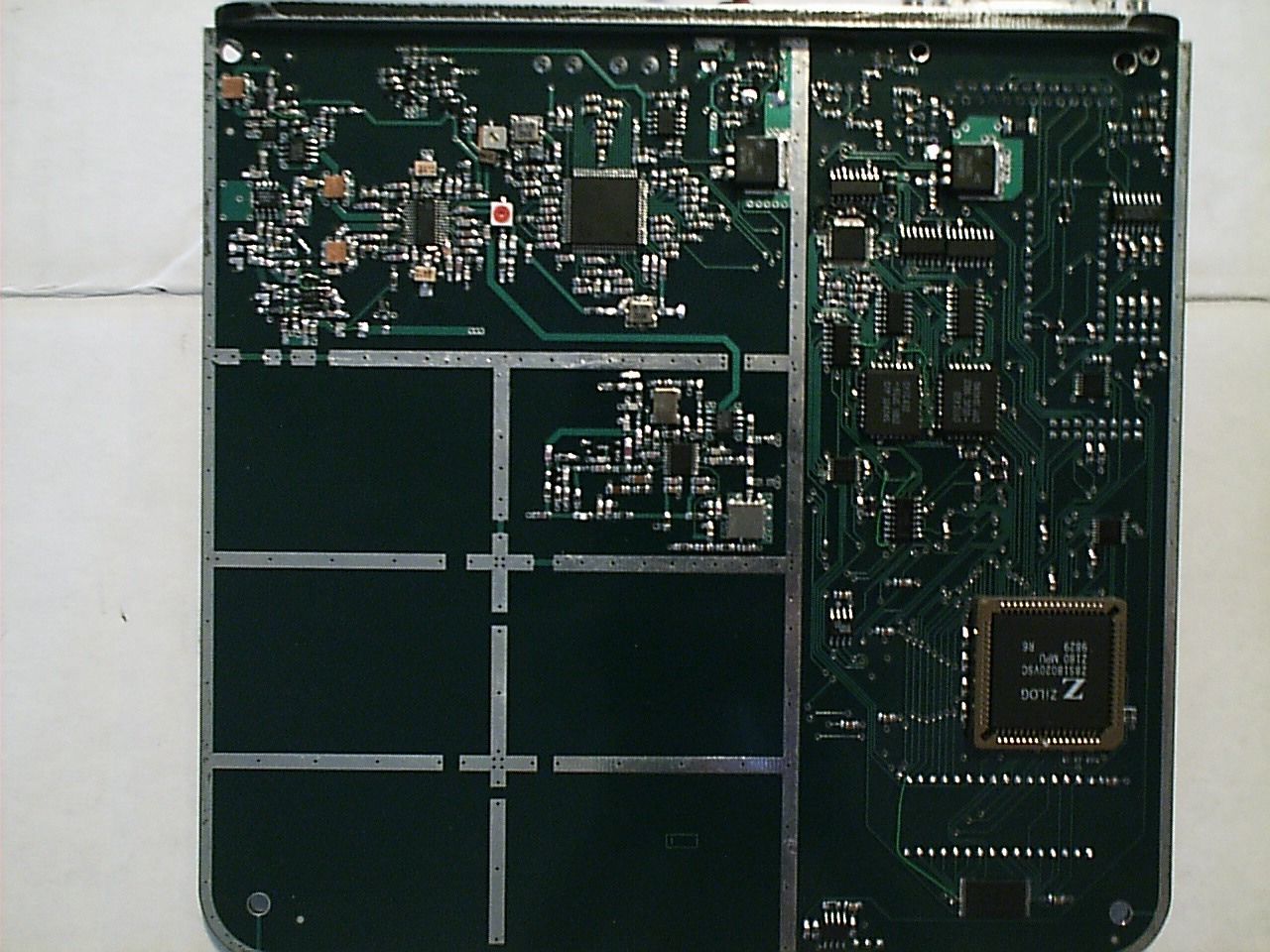
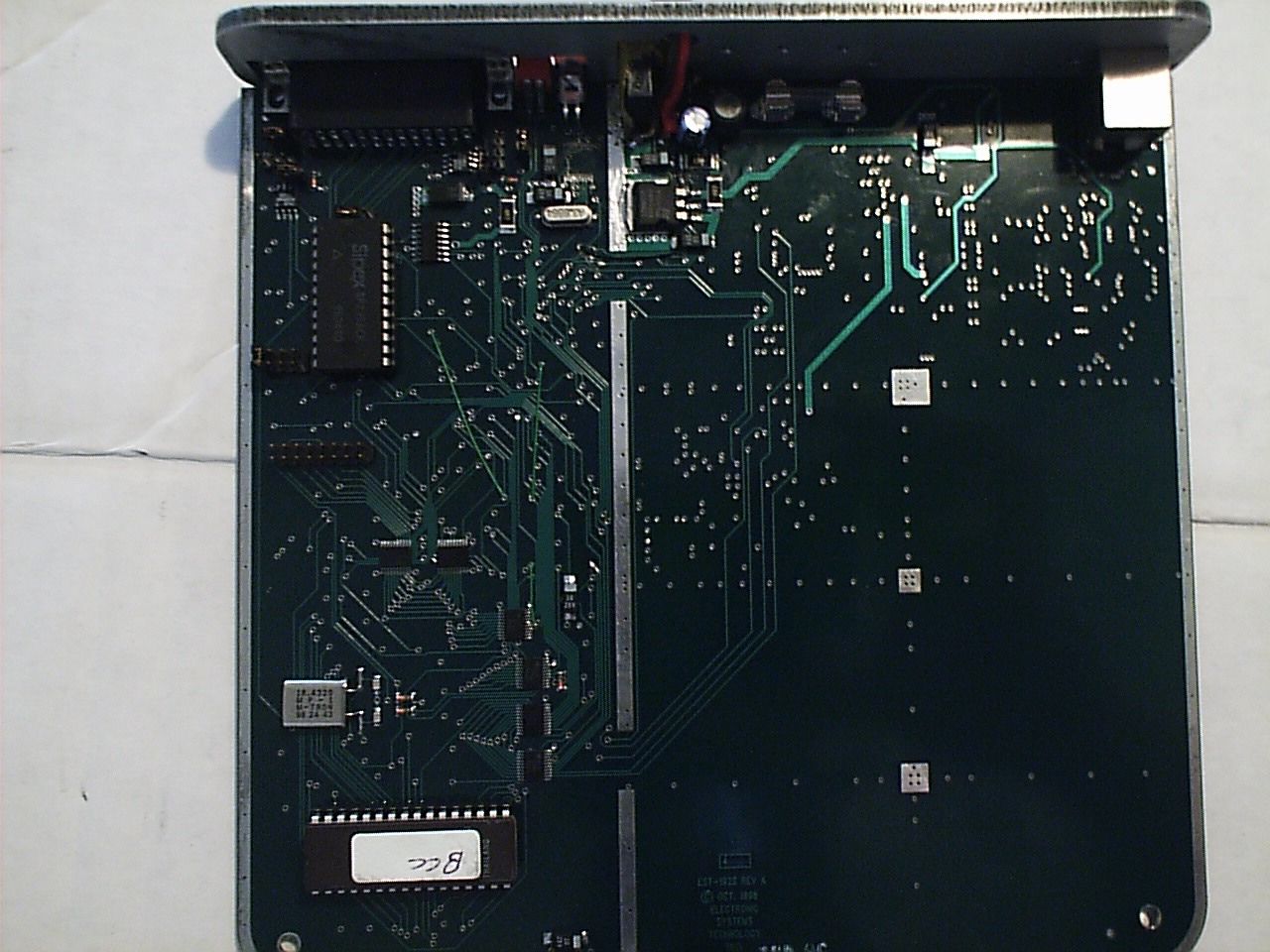
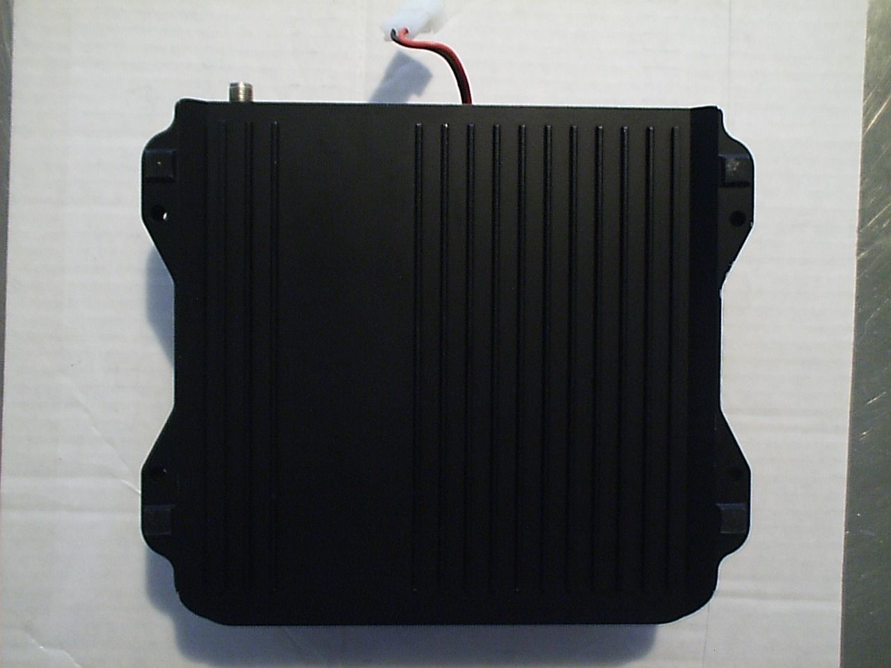
- Wireless Modem
- Frequency Range
- 2412.00000000 - 2462.00000000
- Country
- United States
Documents & Files

Document Text
Text extracted from the exhibit documents filed with the FCC. Open a document above to read the original.
Users Manual
Revision: 1.0 Date: 11 Feb 1999 Electronic Systems Technology (EST) copyrights this manual and the firmware described in it, with all rights reserved. Under the copyright laws, this manual or the firmware internal to the ESTeem unit may not be copied, in whole or part, without the written consent of EST. Under the law, copying includes translating into another language. EST cannot guarantee that you will receive notice of a revision to the firmware described in the manual, even if you have returned a registration/warranty card received with the product. You should periodically check with your authorized EST dealer or call factory direct. EST and the EST logo are registered trademarks of Electronic Systems Technology, Inc. Simultaneously published in the United States and Canada. All rights reserved. ESTEEM USERS MANUAL for MODELS 192S Firmware Versions 1.39 and above. February 1999 Revised: 11 Feb 99 PRODUCT WARRANTY Electronic Systems Technology, Inc., (hereinafter EST) expressly warrants its products as free of manufacturing defects for a period of one year from the date of sale to first user/customer. THERE ARE NO OTHER WARRANTIES, EXPRESS OR IMPLIED AND THERE IS EXPRESSLY EXCLUDED ALL WARRANTIES OF MERCHANTABILITY OR FITNESS FOR A PARTICULAR PURPOSE. NO OTHER WARRANTY GIVEN BY ANY EMPLOYEE, AGENT, DISTRIBUTOR OR OTHER PERSON WITH RESPECT TO THE PRODUCT SHALL BE BINDING ON EST. LIMITATION OF LIABILITY: EST's liability shall be limited to refunding of purchase price, repair or replacement of product. IN NO EVENT SHALL EST HAVE LIABILITY FOR CONSEQUENTIAL, INCIDENTAL, SPECIAL OR EXEMPLARY DAMAGES CAUSED DIRECTLY OR INDIRECTLY BY THE PRODUCT, INCLUDING BUT NOT LIMITED TO ANY INTERRUPTION OF SERVICES, LOSS OF BUSINESS OR ANTICIPATORY PROFITS. IN NO EVENT SHALL EST BE LIABLE FOR ANY DAMAGES WHATSOEVER IN EXCESS OF THE PURCHASE PRICE OF THE PRODUCT. In the event that a unit or part requires replacement or factory servicing, the following conditions apply: a)Customer must obtain from EST an authorized RMA (Return Materials Authorization) number (call 509-735-9092 Customer Support) before shipment of product or parts to EST for any reason; b) If the whole unit is shipped, it must be in its original carton and shipping components, or a carton and shipping components supplied by EST, or if parts only are shipped, they must be packaged and cushioned so as to prevent damage in transit and shipped freight prepaid; PRODUCT WILL BE CONSIDERED OUT OF WARRANTY IF: a)If the product is damaged due to improper or abnormal use, abuse, mishandling, accident or improper maintenance or failure to follow operating instruction; b) If the product is defective as a result of sand, dirt, or water damage; c)If any factory-sealed enclosure has been opened or shows evidence of an attempt to be opened; d) If defects or damage are caused by the use of unauthorized parts or unauthorized service; e)If the product has had its serial numbers altered or removed. Warranty repair form must be accompanied by proof of user's purchase of unit. Product must be shipped to the manufacturer at the following address: Electronic Systems Technology 415 North Quay Street Kennewick, Washington USA 99336 ADDITIONAL SERVICE: If EST releases an improvement update to firmware internal to the ESTeem unit during the 90 day period after the unit was purchased by the first user/customer, EST will update the applicable unit with the revised version at no charge other than for UPS handling and shipping to and from your location to the EST factory. Return of any such item must be accompanied with proof of purchase. TABLE OF CONTENTS Revised: 11 Feb 99 CHAPTER 1 - STARTING OUT Before You Start .................................................... 1-2 ESTeem Utility....................................................... 1-2 Installing ESTeem Utility Software – Windows 95/98/NT ................................................ 1-2 Running The Program ............................................ 1-2 Starting Out ............................................................ 1-2 Basic ESTeem Programming ................................. 1-5 Help Functions ....................................................... 1-5 Saving a Program ................................................... 1-5 Restoring Factory Defaults..................................... 1-5 CHAPTER 2 - MODES OF OPERATION Command Mode ..................................................... 2-2 Converse Mode ...................................................... 2-2 Transparent Mode .................................................. 2-3 Semi-Transparent Mode ......................................... 2-3 Hardware Mode Control......................................... 2-3 CHAPTER 3 - PROGRAMMING ESTEEM FEATURES Digi-Repeating Feature .......................................... 3-2 Global Broadcast Feature ....................................... 3-2 Auto Transmit Feature............................................ 3-3 Auto Connect Feature............................................. 3-3 Multi-Connect Feature ........................................... 3-3 Remote Programming Feature................................ 3-4 Security Feature .................................................... .3-4 Hardware Ring Line............................................... 3-4 Packet Monitor Feature.......................................... 3-5 Using The Infrared Communications Port ............. 3-5 Using The Phone Communications Port ................ 3-6 CHAPTER 4 - ESTEEM APPLICATION PROGRAMS Transparent Auto-Connect ..................................... 4-2 Transparent Auto-Connect Global ......................... 4-2 Interactive Terminal Applications.......................... 4-3 Programmable Logic Controllers ........................... 4-3 CHAPTER 5 - RS-232C/422/485 INTERFACING DTE vs DCE .......................................................... 5-2 Flow Control ..................................................…
Text truncated - open the document above for the full version.
Users Manual
CHAPTER 1 STARTING OUT BEFORE YOU START ESTEEM UTILITY Installing ESTeem Utility Software – Windows 95/98/NT Running The Program STARTING OUT BASIC ESTEEM PROGRAMMING HELP Functions Saving A Program Restoring Factory Defaults CHAPTER 1 STARTING OUT Revised: 11 Feb 99 1-2 BEFORE YOU START Congratulations on your purchase of the ESTeem Wireless Modem! This section of the manual will describe the basic functioning and programming of the ESTeem to get your wireless network up as soon as possible. It is recommended that any first time user of the ESTeem and those that are unfamiliar with its operation complete all steps in this section before proceeding. Take a few minutes to inventory your equipment before you proceed. Report any missing or damaged items to Customer Support as soon as possible. We at Electronic Systems Technology, Inc. (EST) are constantly trying to improve our products and support system so if you have any comments or suggestions on improvement of this manual, please contact us at (509) 735-9092. The completion of this section requires loading the ESTeem Utility program on your computer. The following section will describe the installation and use of this valuable utility program. ESTEEM UTILITY The ESTeem Utility is designed to assist the ESTeem user in programming and troubleshooting. The Utility covers basic operation, programming, PLC applications, and diagnostics of the ESTeem. The ESTeem Utility Program is designed to operate with Windows 95®, Windows 98® and Windows NT®. Installing ESTeem Utility Software Windows 95/98/NT 1. Place the ESTeem CD in your CD-ROM drive (Figure 1). 2. Select Run on the Start Menu. 3. Type (your CD-ROM drive letter):\Utility\Setup.exe 4. Click the OK button and the program will begin installation. Running The Program 1. Select the ESTeem Utility Icon on Start>Programs menu. Figure 2 shows an example of the Main Utility Menu. STARTING OUT This section covers the basics setup and testing for the ESTeem wireless modem. If this is your first experience with the ESTeem wireless modems or you are unclear on how to set the frequency, squelch, or test communication, the ESTeem Starting Out section will guide you through the basics of wireless communication. Figure 2: ESTeem Utility Main Menu RS-232C Interface Cable (EST P/N AA061) 12 VDC Power Supply (EST P/N AA174) 2 Pin Molex Connector ESTeem Model 192S Rear View ESTeem Model 192 Utility Software Windows Version Computer Running Windows 95/98/NT S/N: T/E TX RX PWR IR Port Phon e Model 192S Ant enn a 12 VDC RESET Rubber Duck Antenna (EST P/N AA01S) Figure 1: Installation Diagram CHAPTER 1 STARTING OUT Revised: 11 Feb 99 1-3 1. Select ESTeem Starting Out from the main menu. A window like the one in Figure 3 will be displayed. If this is your first time using the ESTeem wireless modems, select ESTeem Setup Guide for a complete description of all ESTeem functions. Proceed to step 2. 2. Step 1 – Installing External Power window will be displayed (Figure 4). Select Model 192S on the menu and the voltage and current specifications will be displayed. The ESTeem model AA174 power supply can be used with all ESTeem products. If you are using the ESTeem in a solar power application, press Calculate Solar Consumption button for the Amp/Hours required. 3. Press Test External Power Connection button. If you have connected your power cable correctly your Power LED should be illuminated. Press OK to continue. Press Go To Step 2 button to proceed. 4. Step 2 – ESTeem Familiarization window will be displayed (Figure 5). This step will explain the connections to ESTeem Model 192S front panel and provide a setup diagram for testing. 5. Press the Front Panel Description button and a window containing the ESTeem Model 192S front panel will appear (Figure 6). Press any one of the buttons for a complete description of the item’s function. For example, press the Power LED button and the description of the power LED and its use will Figure 3: Starting Out Main Menu Figure 4: Step 1 - Installing External Power Figure 5: Step 2 – ESTeem Familiarization Antenna Connector (TNC-R) 12 VDC Input Power Connector (2 Pin Molex) Reset Switch RS-232, 422 and 485 Input/Output Connector (25 Pin DB Connector) Phone Modem Interface RS-232/422/485 Setup Switches Power LED IR Port Transmit LED Receive LED T/E LED •Link Connect/Disconnect •Auto Connect Enable •Serial Port Framing Error Figure 6: ESTeem Front Panel CHAPTER 1 STARTING OUT Revised: 11 Feb 99 1-4 be displayed. 6. Press the Testing Configuration button and a window containing the Testing Diagram (Figure 1) will be displayed. Press Go To Step 3 button to proceed. 7. Step 3 – Serial Connection window will be displayed (Figure 7). This step will help configure the computer and the ESTeem to communicate with each other. 8. Press Display Cable Diagrams button and all serial pins to the ESTeem Model 192S will be displayed. Press OK to continue. Note:A standard 9-Pin serial port on a computer to ESTeem interface cable is the ESTeem AA061 (Figure 1). 9. Press Change Port Settings. This window will configure the communications port on your computer to operate with the ESTeem modem. Select the operating parameters you wish or set to the default of 19,200,N,8,1. Click OK to continue. 10. Press Set Dip Switches button. This window will configure the ESTeem’s RS-232/422/485 to operate at the setting selected in step 8. Turn both Switches 1 and 2 on the RS-232 setup switches (Figure 6) to the OFF/Down position and press the Reset Button on the ESTeem. Press Download Port Settings button to return to the Step 3 menu. Return Switch 1 on the RS-232/422/485 port setup switches to the ON position and press the reset button. 11. Press Test ESTeem button. If the ESTeem serial interface cable and communication port are operating correctly the ESTeem Welcome Message will be displayed. This will confirm communication between the computer and the ESTeem. If you do not receive a welcome message, follow t…
Text truncated - open the document above for the full version.
Users Manual
CHAPTER 2 MODES OF OPERATION COMMAND MODE CONVERSE MODE TRANSPARENT MODE SEMI-TRANSPARENT MODE HARDWARE MODE CONTROL CHAPTER 2 MODES OF OPERATION Revised: 11 Feb 99 2-2 The ESTeem has three major modes of operation, Command, Converse, and Transparent. This chapter of the manual describes each one of these modes. COMMAND MODE The COMMAND Mode (CMD: prompt) is the default mode that the ESTeem initially enters on power-up or after a hardware or software reset. From this mode the user can command or program the ESTeem. In this mode the user may access the various program commands to configure the ESTeem for the specific application. These values can be stored in nonvolatile memory within the ESTeem by the use of the SAVE command. The ESTeem reads these setup parameters stored in memory on power-up or RESET. When programming in the COMMAND Mode, the user need only enter enough characters to uniquely identify the respective command. Example: CMD:ADD 15 <cr> This enters the source address of the ESTeem to the decimal value of 15. The first three letters ADD were enough for the ESTeem to uniquely identify the command for ADDress. The number of characters that need to be typed varies depending upon the command being entered. In some cases, four or even more letters may have to be entered in order for the identification to be uniquely determined. Up to ten multiple commands can be written on the same line if separated by a colon. Example: CMD:ADD 15:SETC 2:SAVE <cr> CONVERSE MODE This mode allows bi-directional communication from the input/output device attached to the ESTeem to a destination ESTeem and its respective input/output device. The ESTeem will automatically switch to the CONVERSE Mode after the initial CONNECT has been made. When the ESTeem is in the CONVERSE Mode the * prompt will be displayed. The ESTeem will remain in the CONVERSE Mode until the radio link has been broken or by typing a control character defined by the user with the COMMAND variable. The factory default for the COMMAND variable is CTRL C. You can return to the CONVERSE Mode from the COMMAND Mode by typing CONV <cr>. When you are in the CONVERSE Mode the echoing of the character comes from the ESTeem if ECHO = ON (factory default) has been programmed in the ESTeem. Transmitting Data The ESTeem will transmit data from the CONVERSE Mode if one or more of the following conditions have been met. 1.The ESTeem transmit buffer has been filled. The size of the transmit buffer is defined in the ESTeem by the PACKLEN variable. This variable is programmable from 1 to 2000 bytes. Factory default is 2000. 2.The ESTeem receives a SENDPAC (send packet) character from the RS-232C input data stream. The SENDPAC variable can be defined from 0 to 255 by the user. Factory default is 13 (carriage return). The SENDPAC character is also transmitted by the ESTeem. In file dump applications the SENDPAC character can be programmed to be the EOF (end of file) character transmitted from the sending device (i.e.; CTRL Z, CTRL G, etc.). 3.Termination control timer. The termination control timer is enabled by the TERMC (on/off) command. When enabled, the termination timer starts from the time the last transmit buffer has been updated in the RS-232C port. If the termination timer expires before another character is received or transmitted, the contents of the ESTeem transmit buffer will be transmitted. The waiting time of the timer is defined by the TERMT variable (termination time). The programming range of the TERMT variable is 10-255ms. Factory default values are TERMC = OFF and TERMT = 50. It is noted that when the termination timer is used, the SENDPAC variable is usually programmed to be a character that is non occurring in your data stream (i.e.; SENDPAC = 255) so that premature transmission does not occur. TRANSPARENT MODE The TRANSPARENT Mode allows the ESTeem to pass all data characters (O-255 or 0-FF hex) using 8 data bits. CHAPTER 2 MODES OF OPERATION Revised: 11 Feb 99 2-3 To program the ESTeem in the TRANSPARENT mode the TRANSPARent command must be enabled and switch Bit 8 to ON (RS-232C Setup Switch). The TRANSPARent command will defeat the SENDPAC and COMMAND variables and put the ESTeem in the transparent mode when Bit 8 is ON. The transmission of the data packets can only be accomplished by enabling the termination control commands (TERMC and TERMT) or the PACKLEN buffer being filled. The value of TERMT should be slightly longer than the maximum delay encountered during RS-232C transmission. If this time is set to short, the ESTeem will truncate your data stream improperly. When using the TRANSPARENT Mode, data flow control is by hardware handshaking only. Hardware handshaking is initiated by enabling hardware flow control (XHF = ON). The SETCON (Set Connect command) must be used to define the node that you want to communicate with while in the TRANSPARENT Mode. When the TRANSPARENT Mode is enabled you can not communicate to the ESTeem in the COMMAND Mode unless you use the Hardware Mode Control line (see explanation this chapter). To remove the ESTeem from the TRANSPARENT Mode the user must perform the following: 1.Switch Bit 8, Off on the RS-232C Setup Switch. 2.Reset the ESTeem from the front panel switch. 3. Type Tra OFF <cr>. SEMI-TRANSPARENT MODE This mode should be utilized when sending a non-ASCII file and there is a possibility that the SENDPAC character could be contained in the transmitted data set. Perform the following prior to programming the ESTeem to initialize the unit to factory default settings: 1.Turn Bit 8, OFF on the RS-232C Setup Switch. 2.Reset the ESTeem. 3.TYPE FA <cr>. Please note the characters may or may not be echoed by the CRT. ESTeem ------------------------- ADDxxxxxx = your address SETCyyyyyy = destination address TERMCON TERMT10 SENDP255 EDITOFF SAVE If EDIT is off, and SENDPAC = 255, the SENDPAC character is disabled. This character when received will not cause packet transmission and will be pas…
Text truncated - open the document above for the full version.
Users Manual
CHAPTER 3 PROGRAMMING ESTEEM FEATURES DIGI-REPEATING FEATURE GLOBAL BROADCAST FEATURE AUTO TRANSMIT FEATURE AUTO CONNECT FEATURE MULTI-CONNECT FEATURE REMOTE PROGRAMMING FEATURE SECURITY FEATURE HARDWARE RING LINE FEATURE PACKET MONITOR FEATURE USING THE INFRARED COMMUNICATIONS PORT USING THE PHONE COMMUNICATIONS PORT CHAPTER 3 PROGRAMMING ESTEEM FEATURES Revised: 11 Feb 99 3-2 Listed in this chapter are the major ESTeem features and programming examples on how to use them. These features are individual building blocks to solve your application needs. Remember your particular application my require one or more of these features enabled. DIGI-REPEATING The Repeater feature allows an ESTeem to relay it's respective transmission or packet through a maximum of three ESTeems to increase the operating range of the unit. Any ESTeem in your radio network can function as a repeater for any other ESTeem. This is independent of the fact that the ESTeem being used as a repeater is linked or connected to another node, therefore an ESTeem can function as a repeater, operational node, or both at the same time. The data that is digi-repeated through an ESTeem will not be output through the repeating ESTeem’s RS-232C port. To specify one or more ESTeems as repeaters, the CONNECT command has been expanded to except up to three added addresses as follows: CONN r1,r2,r3,da r1 =Address (1 to 254) of first ESTeem repeater. r2 =Address (1 to 254) of second ESTeem repeater. r3 =Address (1 to 254) of third ESTeem repeater. Da =Address (1 to 255) of destination ESTeem. Note:Address 255 is used for Global. When transmitting packets through other ESTeems, the source ESTeem will automatically adjust it's FRACK time to allow additional time for the packet to reach its destination and for the returned acknowledgment. Frack time takes into account the packet size and the number of repeaters specified. The ACK still comes from the destination ESTeem, not the first or any repeater. For testing purposes, you can loop back a connection to yourself by placing your source address in the destination address of the repeater string. Any data transmitted will repeat through the repeater address and display back on the screen. Example: CONN r1,Sa r1 =Address (1 to 254) of first ESTeem repeater. Sa =Address of local ESTeem. Any ESTeem command in this manual that uses an address string can be configured to use the Digi-repeating feature. Example: SETC r1,r2,r3,da GLOBAL BROADCAST Global broadcast is the ability of one ESTeem to transmit it's message to more than one ESTeem at one time. All ESTeems within radio range will receive the message whether or not they are connected to another ESTeem or in command or converse mode. You can put your ESTeem in Global by connecting or programming the SETC to address 255. Address 255 is a non assignable unit address and is used by the ESTeem CPU to access this special mode. When an ESTeem is in Global, the standard ACK protocol from the receiving ESTeem is disabled, but the 32 bit CRC error checking on the received ESTeem is still operational. When you perform CONN 255 <cr> from the COMMAND MODE the ESTeem will immediately go to the CONVERSE MODE (* is displayed). All messages sent will be transmitted globally to all ESTeems in radio range. In the ESTeem you have a GLOBAL (on/off) command. When GLOBAL = On, you can receive Global transmissions. If GLOBAL = Off you will not display Global transmissions from other ESTeems. Note: Factory default is ON. By using the repeater function you can transmit Global messages from another ESTeem using the Digi-repeating feature. Example: CONN 10,20,30,255<cr> SETC 10,20,30,255<cr> By adjusting these commands you can route from unit 10 to 20, 20 to 30, and go Global at unit 30. CHAPTER 3 PROGRAMMING ESTEEM FEATURES Revised: 11 Feb 99 3-3 You can enable global transmissions in more than one ESTeem in your network. This will allow global communications between all ESTeems within radio range. AUTO TRANSMIT The Auto Transmit feature of the ESTeem allows the user to transmit a data packet without filling up the PACKLEN (packet length) buffer or defining a special control character using the SENDPAC (send packet) variable. The Auto Transmit feature is a timer that is enabled in the ESTeem that monitors traffic in and out of the RS-232C port. If there are characters in the RS-232C buffer, the termination control timer starts from the time the last receive or transmitted character is updated in the buffer. If the termination time expires before another character is received or transmitted, the received characters are transmitted. To enable this feature perform the following from the COMMAND MODE: TERMC (on/off) =On. Enable termination control. TERMT (10-255) =One unit number equals 1ms. TERMC is the termination control command. TERMT is the termination time command. Factory default for TERMC = Off and TERMT = 10. AUTO CONNECT The Auto Connect feature allows the user to program the ESTeem to perform a CONNECT to another ESTeem when data is sent to the RS-232C communications port. To enable this feature perform the following from the COMMAND MODE: SETCON (1-255) =Address of destination ESTeem. Remember, you can use the Repeater routing (r1,r2,r3,da) or put the ESTeem in Global (address 255). SETCON is the set connect command. SASAVE command. This will save the SETC variable to the non volatile memory so that it will not be lost when the ESTeem is RESET. Bit 8 (on/off) =On. Bit 8 is located on the RS-232C SETUP SWITCH on the rear of the ESTeem. The ESTeem must be RESET after the Bit has been changed to be read by the ESTeem CPU. RESET ESTeem RESET is located on the front panel OFF/ON switch. The T/E light on the front panel of the ESTeem should now flash at a two times per second rate. MULTI-CONNECT The actual polling of the ESTeem must originate from the host device connected to the ESTeem using the CONNECT command to originate the initial connect and the COMMAND chara…
Text truncated - open the document above for the full version.
Users Manual
CHAPTER 4 ESTEEM APPLICATION PROGRAMS TRANSPARENT AUTO CONNECT TRANSPARENT AUTO CONNECT GLOBAL INTERACTIVE TERMINAL APPLICATIONS PROGRAMMABLE LOGIC CONTROLLERS CHAPTER 4 ESTEEM APPLICATION PROGRAMS Revised: 11 Feb 99 4-2 Listed below are different application programs to aid the user in programming the ESTeem. TRANSPARENT AUTO-CONNECT This mode is used for a dedicated point to point application. The ESTeem will initiate the radio link when data is received by the RS-232/422/485 port. Perform the following prior to programming the ESTeem(s) to initialize the unit to factory default settings: 1.Turn Bit 2 OFF on the RS-232C Setup Switch. 2.Reset the ESTeem. 3.TYPE FA <cr>. Please note the characters may not be echoed by the CRT. ESTeem AESTeem B ---------------------------- -------------------------------- ADDxxxADDyyy SETCyyySETCxxx TERMCONTERMCON TERMT10TERMT10 XHFON *XHFON * DISACKON *DISACKON * TRANS ONTRANS ON SAVESAVE Bit 8 ON Bit 8 ON (RS-232 Switch) Reset ESTeemReset ESTeem Notes: • Turn DISACK ON only if you want to defeat the acknowledge packet. • xxx and yyy represent an ESTeem address which is user definable from 1 to 254. TRANSPARENT AUTO-CONNECT GLOBAL This mode is usually used for a point to multi-point applications when a customers devices include their own addressing protocol to communicate between devices. The ESTeem packet addressing and acknowledge protocol is defeated. All ESTeems will receive the data transmission. The 16 bit CRC error checking on received data is still enabled. This program is used in all ESTeems, the only difference is the unit addresses. Perform the following prior to programming the ESTeem(s) to initialize the unit to factory default settings: 1.Turn Bit 2 OFF on the RS-232C Setup Switch 2.Reset the ESTeem. 3.TYPE FA <cr>. Please note the characters may not be echoed by the crt. ESTeem A ---------------------------------------------------- ADDxxx (xxx = ESTeem address) SETCON255 TERMCON TERMT10 XHFON * TRANS ON SAVE Bit 2ON (RS-232 Switch) Reset ESTeem Note:Only hardware flow control can be used in this mode. CHAPTER 4 ESTEEM APPLICATION PROGRAMS Revised: 11 Feb 99 4-3 INTERACTIVE TERMINAL APPLICATION This program is used to connect a mainframe to a remote terminal. This setup is a typical point to point configuration with the AUTO-CONNECT feature enabled. Perform the following prior to programming the ESTeem(s) to initialize the unit to factory default settings: 1.Turn Bit 2 OFF on the RS-232C Setup Switch. 2.Reset the ESTeem. 3.TYPE FA <cr>. Please note the characters my not be echoed by the crt. ESTeem At MainframeESTeem At Terminal ------------------------------------------------------ ADDxxxADDyyy SETCyyySETCxxx TERMCONTERMCON TERMT10 TERMT10 XSFOFFXSFOFF XHFON *XHFON * DISACKON *DISACKON * TRANSONTRANSON SAVESAVE Bit 2 ONBit 2 ON (RS-232 Switch) RESET ESTeemRESET ESTeem Notes: • Turn DISACK ON only if you want to defeat the acknowledge packet. • Only hardware flow control can be used in this mode. • xxx and yyy represent an ESTeem address which is user definable from 1 to 254. PROGRAMMABLE LOGIC CONTROLLERS EST has available complete Engineering Reports for each PLC manufacturer make. These reports are available on our web site at www.esteem.com or will be provided at no charge by calling EST Customer Support on 509-735-9092.
Users Manual
CHAPTER 5 RS-232C/422/485 INTERFACING DTE VS DCE FLOW CONTROL MEMORY BUFFERS DATA TERMINAL READY RS-422/485 CONFIGURATION RS-232/422/485 PORT PINOUT TABLE CHAPTER 5 RS-232C/422/485 INTERFACING Revised: 11 Feb 99 5-2 DTE vs. DCE The ESTeem is configured as a Data Communication Equipment (DCE) device. The following signals are available at the RS-232C connector located at the front of the unit. PinDescription --------------------------------------------------------------------- 1FGShield Ground 2TXDTransmit Data (Input) 3RXDReceive Data (Output) DCE4RTSRequest To Send (Input) 5CTSClear to Send (Output) 7SGSignal Ground 8DCDData Carrier Detect (Output) 12RTSRequest To Send (Output) 20DTRData Terminal Ready (Input) 22RingRing Indicator (Output) The important thing to remember is that for the ESTeem to communicate with an external device, the data output from pin 3 of the ESTeem RS-232C connector must be connected to the data input of the device you are connected to; otherwise, the ESTeem won't work. Likewise, the data input to pin 2 of the ESTeem must be connected to the data output of the device you are connected to. Normally, if the equipment you are connecting to looks like a terminal or computer (DTE), its input, Receive Data (RXD), will be on pin 3 its output, Transmit Data (TXD), will be on pin 2. Therefore, the ESTeem can be connected directly. If the device you are connecting to is configured as a modem (DCE), its output will be on pin 3. If this configuration is connected to the ESTeem, damage may result to the ESTeem or the connecting device. In this case, you can purchase a null connector that internally reverses pins 2 and 3. Whatever your situation may be, it is always best to check the manual on your particular device and connect accordingly. Purchase or fabricate a RS-232C shielded cable for your ESTeem. The ESTeem requires a standard male 25 pin D connector on one end of the cable for proper connection. Remember to install the small retaining screws on either side of the cable connector. Tightening these screws keeps you from accidentally losing connection with your ESTeem. Notes: • The ESTeem requires a shielded RS-232 cable. This is to prevent unwanted electrical noise from entering the ESTeem and also to prevent any electrical noise from getting out of the ESTeem. • Remember -- always use a shielded RS-232C cable. • Pins 9, 10, 14, & 16 are used for RS-422/485 interfacing and should be left open if not used. FLOW CONTROL The ESTeem can be enabled to support SOFTWARE or HARDWARE flow control. Software Flow Control Software flow control is enabled by the XSFLOW (on/off) command in the ESTeem. When XSFLOW is …
Text truncated - open the document above for the full version.
Contact Information
Applicant
Todd Elliott(Engineer)
Technical Contact
Acme TestingPaul G Slavens
[email protected]360 595-2785
2002 Valley Highway · Acme, Washington · United States
Non-Technical Contact
Acme TestingDesiree R Patterson
[email protected]360 595-2785
Test Firm
Acme Testing Co.Harry Hodes
Technical Specifications
| # | Rule Parts | Frequency Range | Power Output |
|---|---|---|---|
| 1 | 15C | 2.41 GHz - 2.46 GHz | 740.00 mW |
Other Applications from Electronic Systems Technology
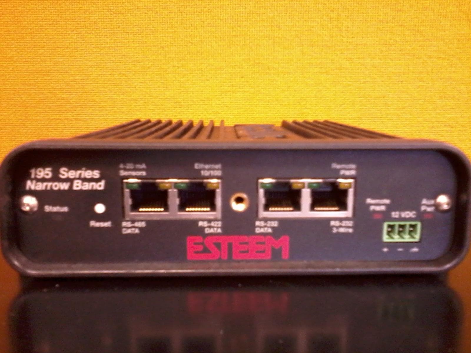
ENPESTEEM195H
Aug 12, 2014217-220MHz VHF Telemetry Modem
Equipment Class
TNB - Licensed Non-Broadcast Station Transmitter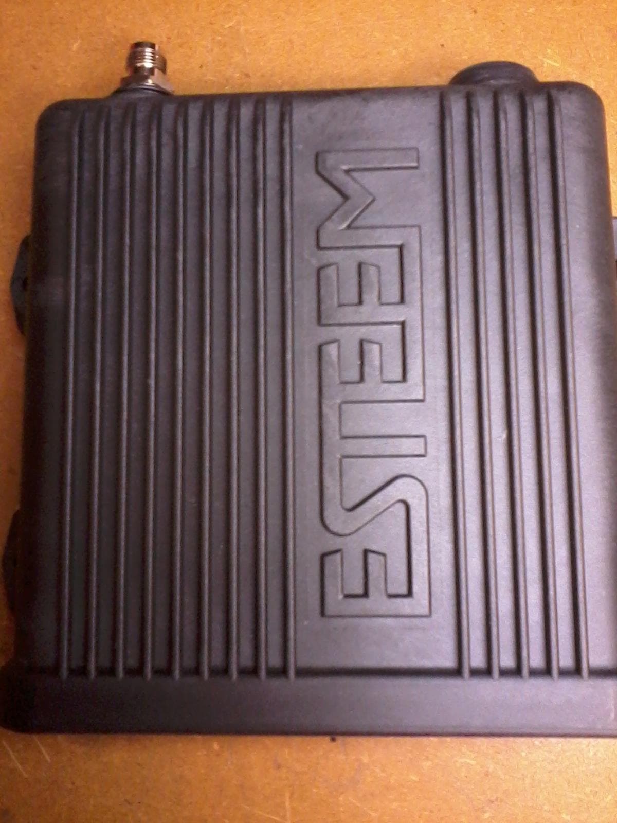
ENPESTEEM195C
Dec 19, 2013450-470MHz Narrow-band UHF modem
Equipment Class
TNB - Licensed Non-Broadcast Station Transmitter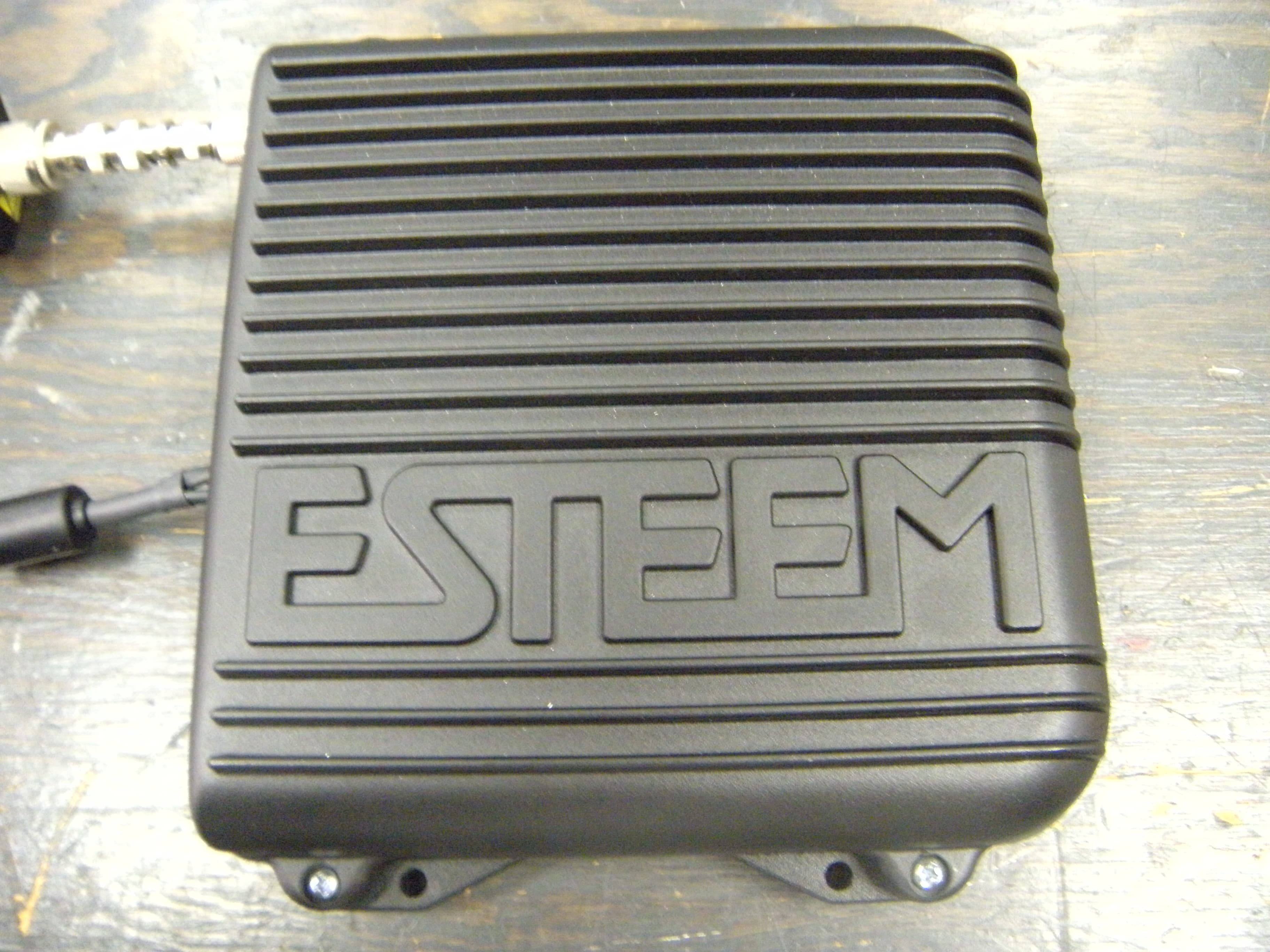
ENPESTEEM210M
Sep 05, 2013Data radio modem
Equipment Class
TNB - Licensed Non-Broadcast Station Transmitter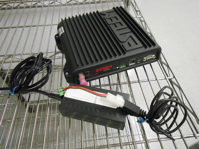
ENPESTEEM210C
Mar 10, 2013Data radio modem
Equipment Class
TNB - Licensed Non-Broadcast Station Transmitter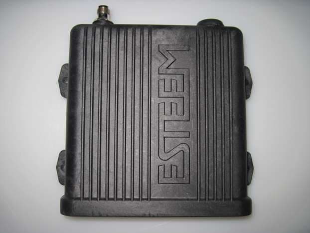
ENPESTEEM195EA
Feb 12, 2012Wireless LAN transceiver
Equipment Class
DTS - Digital Transmission System