ENPESTEEM195ED-1Wireless LAN transceiver
Electronic Systems Technology
Click to zoom
Application Details
- Equipment Class
- DTS - Digital Transmission System
- Date of Grant
- Mar 23, 2011
- Application Purpose
- Original Equipment
- Date of Application
- Mar 23, 2011
- Equipment Note
- Wireless LAN transceiver
- Frequency Range
- 907.00000000 - 922.00000000
- Country
- United States
Documents & Files
Document Text
Text extracted from the exhibit documents filed with the FCC. Open a document above to read the original.
Users Manual
ESTeem MODEL 195Ed USER’S MANUAL Manual Revision 1.0 June 2008 Electronic Systems Technology, Inc. ESTeem MODEL 195Ed USER’S MANUAL Manual Revision 1.0 Firmware Version 302.8.102 and above June 2008 Prepared by: Date: Name: Eric P. Marske Title: Product Manager Approved by: Date: Name: Tom L. Kirchner Title: President WARRANTY INFORMATION Electronic Systems Technology, Inc., (dba ESTeem Wireless Modems here after EST) expressly warrants its products as free of manufacturing defects for a period of one year from the date of sale to first user/customer. THERE ARE NO OTHER WARRANTIES, EXPRESS OR IMPLIED AND THERE IS EXPRESSLY EXCLUDED ALL WARRANTIES OF MERCHANTABILITY OR FITNESS FOR A PARTICULAR PURPOSE. NO OTHER WARRANTY GIVEN BY ANY EMPLOYEE, AGENT, DISTRIBUTOR OR OTHER PERSON WITH RESPECT TO THE PRODUCT SHALL BE BINDING ON EST. COPYRIGHT INFORMATION This manual and the firmware described in it are copyrighted by EST, with all rights reserved. Under the copyright laws, this manual or the firmware internal to the ESTeem unit may not be copied, in whole or part, without the written consent of EST. Under the law, copying includes translating into another language. EST cannot guarantee that you will receive notice of a revision to the firmware described in the manual, even if you have returned a registration/warranty card received with the product. You should periodically check with your authorized EST dealer or call factory direct. EST and the ESTeem logo are registered trademarks of Electronic Systems Technology, Inc. Simultaneously published in the United States and Canada. All rights reserved. LIMITATION OF LIABILITY: EST's liability shall be limited to refunding of purchase price, repair or replacement of product. IN NO EVENT SHALL EST HAVE LIABILITY FOR CONSEQUENTIAL, INCIDENTAL, SPECIAL OR EXEMPLARY DAMAGES CAUSED DIRECTLY OR INDIRECTLY BY THE PRODUCT, INCLUDING BUT NOT LIMITED TO ANY INTERRUPTION OF SERVICES, LOSS OF BUSINESS OR ANTICIPATORY PROFITS. IN NO EVENT SHALL EST BE LIABLE FOR ANY DAMAGES WHATSOEVER IN EXCESS OF THE PURCHASE PRICE OF THE PRODUCT. In the event that a unit or part requires replacement or factory servicing, the following conditions apply: a) Customer must obtain from EST an authorized RMA (Return Materials Authorization) number (call 509-735-9092 Customer Support) before shipment of product or parts to EST for any reason; b) If the whole unit is shipped, it must be in its original carton and shipping components, or a carton and shipping components supplied by EST, or if parts only are shipped, they must be packaged and cushioned so as to prevent damage in transit and shipped freight prepaid; PRODUCT WILL BE CONSIDERED OUT OF WARRANTY IF: a) If the product is damaged due to improper or abnormal use, abuse, mishandling, accident or improper maintenance or failure to follow operating instruction; b) If the product is defective as a result of sand, dirt, or water damage; c) If any factory-sealed enclosure has been opened or shows evidence of an attempt to be opened; d) If defects or damage are caused by the use of unauthorized parts or unauthorized service; e) If the product has had its serial numbers altered or removed. Warranty repair form must be accompanied by proof of user's purchase of unit. Product must be shipped to the manufacturer at the following address: ESTeem Wireless Modems 415 North Quay Street Building B-1 Kennewick, Washington USA 99336 ADDITIONAL SERVICE: If EST releases an improvement update to firmware internal to the ESTeem unit during the 90 day period after the unit was purchased by the first user/customer, EST will update the applicable unit with the revised version at no charge other than for UPS handling and shipping to and from your location to the EST factory. Return of any such item must be accompanied with proof of purchase. TABLE OF CONTENTS Revised: 11 Aug 08 Page 1 EST P/N AA107D CHAPTER 1 – INTRODUCTION Before You Begin 1-1 Model 195Ed Overview 1-1 Model 195Ed Configuration Modes 1-1 Access Point Modes --------------------------------------------- 1-2 Access Point Repeater --------------------------------------------- 1-3 Self-Healing Mesh Network --------------------------------------------- 1-3 Station Mobile Client Modes --------------------------------------------- 1-3 Serial Applications (Optional) --------------------------------------------- 1-4 CHAPTER 2 – CONFIGURATION DIAGRAMS Model 195Ed Access Point Configurations 2-1 Figure 1: Single Access Point Bridge Diagram --------------------------------------------- 2-1 Figure 2: Multiple Access Point Bridge Diagram --------------------------------------------- 2-1 Figure 3: Access Point Router Diagram --------------------------------------------- 2-2 Figure 4: Access Point Masquerade Diagram --------------------------------------------- 2-2 Model 195Ed Access Point Repeater with Clients Configurations 2-3 Figure 5: Access Point Bridge Repeater with Clients Diagram --------------------------------------------- 2-3 Figure 6: Access Point Router Repeater with Clients Diagram --------------------------------------------- 2-3 Figure 7: Access Point Masquerade Repeater with Clients Diag. --------------------------------------------- 2-4 Model 195Ed Building to Building Configurations 2-4 Figure 8: Building to Building Configuration Diagram --------------------------------------------- 2-4 Figure 9: Building to Building with Repeater Diagram --------------------------------------------- 2-5 Figure 10: Building to Building Router Diagram --------------------------------------------- 2-5 Model 195Ed Complete Wireless Solutions 2-6 Figure 11: Complete Bridge Network Solutions Diagram --------------------------------------------- 2-6 Figure 12: Complete Router Network Solutions Diagram --------------------------------------------- 2-7 Model 195Ed Serial Network Configurations 2-8 Figure 13: Point to Point Serial Diagram -- ------------------------------------------- 2-8 Figure 14: Point t…
Text truncated - open the document above for the full version.
Users Manual
CHAPTER 3 STARTING OUT Revised: 27 Jun 08 3-6 EST P/N AA107D 4. Connect the Model 195Ed to your computer either direct to the Ethernet card or through a HUB/Switch using a CAT-5e Ethernet cable. The Ethernet port on the 195Ed supports Auto-Negotiation so either a patch cable or crossover cable will work. Open the ESTeem Discovery Program and press the Discover Modems button. The Model 195Ed will be displayed in the program by the Ethernet MAC address and Current IP Address (Figure 7). Note: The SSID and Mode of Operation will be adjusted later in the configuration. 5. Double-click on the 195Ed you want to program and the Configure IP Address window will be displayed (Figure 8). Enter an IP address and Subnet Mask for the 195Ed that matches your network subnet and press the OK button to save this to the ESTeem. You will receive notification that the Configuration was Successful and the 195Ed will reboot. Proceed to ESTeem Setup in Chapter 4. Figure 7: Discovery Program Main Page Figure 8: Change IP Address Window CHAPTER 3 STARTING OUT Revised: 27 Jun 08 3-7 EST P/N AA107D USING THE RS-232 INTERFACE Any terminal emulation program that can run with VT100 emulation can be used for this configuration of the ESTeem. Most Windows users will probably use either Hyper Terminal or the Terminal Emulation in the ESTeem Utility program. Configure your RS-232C port for a Baud Rate to 38,400, Data Bits to 8, Parity to None, Stop Bits to 1 and Handshaking to None and set the Emulation type to VT100. Once your ESTeem has an IP address, you can attach the ESTeem to your network and use the Web Server for further programming. Programming Using the RS-232 Port 1. When configuring the Model 195Ed for the first time you can use the ESTeem RS-232C Configuration Menu to setup the basic operating parameters such as assigning the IP Address, IP Net Mask, Gateway IP Address, Domain Name, and DNS IP Address. 2. Connect the serial cable (EST P/N: AA0621.1) between the RS-232 connector (RJ-45) on the Model 195Ed’s programming port to the serial port on the computer. 3. Any terminal emulation program can be used for the configuration of the Model 195Ed. Most users will use either the Terminal Emulation section of the ESTeem Utility Program or Hyper Terminal in Windows. Configure your RS-232C port for a Baud Rate to 38,400, Data Bits to 8, Parity to None, Stop Bits to 1, use No Handshaking (Flow Control) and set the Terminal to VT100 emulation. 4. Plug the Model AA175 power supply into a wall socket and connect an Ethernet patch cable from the Model 195Ed Ethernet port to the J1 (Data&PWR) port on the power supply (Figure 4). The Power over Ethernet (POE) LED on the front of the ESTeem should be illuminated. 5. If your computer is configured properly, you will see the ESTeem Model 195Ed booting sequence on your Terminal Emulation program. Once the ESTeem boot sequence is complete (approximately 30 seconds) you will receive this message: “Please press Enter to active this console.” If you don’t see this message press the Reset button on the front panel of the Model 195Ed and/or check the programming of your RS-232 port. 6. Press the Enter key and you will be at the Configuration Menu 195Ed login prompt. See Figure 10. Figure 10: RS-232 Port Log-in Screen CHAPTER 3 STARTING OUT Revised: 27 Jun 08 3-8 EST P/N AA107D 7. To enter the Model 195Ed Main Menu you will need to log into the system with a login name and password. 8. If this is not the first time configuration of the Model 195Ed, see your network systems administrator for the password. 9. At the 195Ed login prompt type admin for the login name and press the Enter key (<Enter>). The login name is defined at the factory and is not changeable by the user. Note that all characters are lower case. 10. If this is the first time the Model 195Ed has been programmed or the Password was not changed from the factory default values, the factory default password is also admin. Enter admin for the password and press the Enter key (<Enter>). Note: All characters are lower case. The ESTeem Configuration Welcome Screen (Figure 11) will now be displayed. 11. To set the IP address in the ESTeem 195Ed, type the letter A and press the Enter key. Enter the value for the IP address, Netmask and default route and pressing the Enter key after each entry. 12. After the basic parameters have been entered into the Model 195Ed you will need to commit the changes to the Model 195Ed (Figure 12). Press the C key and then the Enter and the changes will be saved to flash memory. You can use programming features in the ESTeem Web Configuration Manager to configure the unit for your application. Proceed to Chapter 4. Figure 11: RS-232 Welcome Screen Figure 12: RS-232 Welcome Screen CHAPTER 4 WEB CONFIGURATION Revised: 27 Jun 08 4-1 EST P/N AA107D The ESTeem Model 195Ed Web Configuration Manager is an internal web server that will allow setup, monitoring and diagnostics of all operating parameters in the Model 195Ed. The 195Ed can be configured using any current web browser software such as Internet Explorer, Netscape or Mozilla. LOGGING ON TO THE ESTeem WEB PAGE 1. Using your Web Browser connect to the Model 195Ed Web Page with the IP Address that you have assigned it in Chapter 3. 2. You will now see the Log-on Menu on Figure 1. To enter the Model 195Ed Top Menu you will need to log into the system with a User Name and Password. 3. For the User Name enter admin and press the Enter key (<Enter>). The User Name is defined at the factory and is not changeable. 4. Enter your Password and press the Enter key (<Enter>). If this is the first time the Model 195Ed has been programmed and Password was not changed from the factory default values, proceed with the steps below to access the Configuration Menu. • The factory default Password is also admin. Enter admin for the Password and press the Enter key (<Enter>). • Note: All characters are lower case. 5. After Log-in the next screen displayed will be the M…
Text truncated - open the document above for the full version.
Users Manual
CHAPTER 8 ANTENNA SETUPS Revised: 11 Aug 08 8-3 EST P/N AA107D ASSEMBLING THE AA195PM TWO HOLE OUTDOOR POLE MOUNTING KIT The AA195PM mounting kit contains everything required for pole mounting and weatherproofing the ESTeem Model 195E for outdoor installations. The 195E with AA195PM mounting kit can be directly mounted to a round pole from 1.25” to a diameter of 2.25” OD. Any mounting structure greater than 2” requires hose clamp strapping run through the Pole Mount Brackets. The mounting kit requires the following assembly: 1. If you purchased an AA195PM mounting kit with your Model 195E, the kit will be packed in the same packing box as the ESTeem (Figure 1). 2. Remove and inventory the two (2) Pole Mounting Brackets, one (1) Two-Hole Face Plate Cover (with single port cover installed), one (1) Heat Shield and (1) AA195PM Hardware bag from the packing box (Figure 1). Report any missing or damaged items to ESTeem Customer Support (509-735-9092 Phone) as soon as possible for replacement. Figure 1: Packet Box Contents Figure 2: AA195PM Hardware Contents (2) Square Bend U-Bolts with Hardware (2) Pole Mount Clamps (4) 10-24 Pan Screws (2) Ethernet Cable Boot (1) Weather Proof Boot for Antenna Port B (if not used) (2) Direct Mount Antenna Boots for ESTeem Approved Direct Mount Antenna Only CHAPTER 8 ANTENNA SETUPS Revised: 11 Aug 08 8-4 EST P/N AA107D 3. Inventory the AA195PM Hardware bag for all the components listed in Figure 2. 4. Assemble the two Pole Mounting Brackets with the included U-bolts, hardware and Pole Mount Clamps. Reference Figure 3. 5. Place the four supplied 10-24 x 1” Phillips Pan Head screws through the mounting holes of the Heat Shield and attach to the to the top of the ESTeem 195E (Figure 4). Figure 3: Pole Mount Assembly Figure 4: Heat Shield Attachment CHAPTER 8 ANTENNA SETUPS Revised: 11 Aug 08 8-5 EST P/N AA107D 6. Attach the two Pole Mounting Brackets to the ESTeem Model 195E with the 10-24 x 1” Phillips Pan Head screws through the top of the heat shield. Reference Figure 5 (Heat Shield removed for detail). 7. Assemble the outdoor rated CAT-5e Ethernet cable (Not Provided) with the supplied Ethernet Cable Boot (Figure 6). 8. Feed the CAT-5e Ethernet connector(s) through the Face Plate Cover and secure the Ethernet Cable Boot to the cover. Reference Figure 7. NOTE: The Ethernet cable boot must be installed before the RJ-45 end is installed. If using the ESTeem AA09.1 outdoor Ethernet cable, verify that the Ethernet cable boot end is routed toward the ESTeem 195E. Figure 5: Pole Mount Connection to Case (Heat Shield Removed for Detail) Ethernet Cable Boot Figure 6: Ethernet Cable Assembly CHAPTER 8 ANTENNA SETUPS Revised: 11 Aug 08 8-6 EST P/N AA107D 9. Route the CAT-5e Ethernet cable through the molded strain-relief fins in the Face Plate Cover (Figure 8) to secure the cable and provide strain-relief for the connector. If a second Ethernet cable is installed, remove the second port cover and route cable. 10. Plug the CAT-5e Ethernet cable to the Model 195E’s Ethernet port and secure the Face Plate Cover with the attached thumb screw. Verify that the weatherproof seal on the Face Plate Cover is sealed against the outer rim of the Model 195E. Reference Figure 9. 11. Attach the antenna connector boots as show in Figure 10 for either dual attached antennas or external antennas. You are now ready to mount the ESTeem Model 195E Figure 8: Face Plate Cover Strain Relief Figure 9: Face Plate Cover Installed on ESTeem Figure 7: Ethernet Cable Routing Face Plate Cover Ethernet Cable Boots Second Port Cover Remove for 2 nd Cable CHAPTER 8 ANTENNA SETUPS Revised: 11 Aug 08 8-7 EST P/N AA107D Caution: Outdoor mounting of the 195E requires the use of weatherproof boots. Improper installation could result in radio failure. Caution: Always mount the 195E vertically with the antenna ports on top. Figure 10: Completed AA195PM Mounts Direct Mount Antenna Boots Port A EST Approved Direct Mount Antenna Only Port B EST Approved External Antenna With Factory Installed Boot Weather Proof Boot NOTE: Remove Plastic Connector Cover Before Installation Face Towards The South (North America) CHAPTER 8 ANTENNA SETUPS Revised: 11 Aug 08 8-8 EST P/N AA107D Caution: Always mount the 195Ed vertically with the antenna ports on top. Model 195Ed with Direct Mount Antenna and Surge Protection Weatherproof Front Cover Direct Pole Mount Pole Mounting Kit EST P/N AA195PM Weatherproof Boot Pole Mounting Brackets (not shown) Omni-Directional Antenna EST P/N AA20DMEs Antenna Port A ESTeem Resources EST Part No. AA109 RS-232 Programming Interface Cable EST Part No. AA0621.1 Weatherproof Boot POE Cable EST P/N AA09.1 (300 ft. maximum) Serial Interface Cable EST P/N AA09.1 (50 ft. maximum) Weatherproof Boot In Building 100-250 VAC 50-60 Hz POE Supply EST P/N AA175 Ethernet LAN Interface Cable Cable RS-232, RJ-45/DB9F EST P/N AA0621.1 RS- 232C Serial Interface Earth Ground Ethernet Surge Protection EST P/N AA166 CHAPTER 8 ANTENNA SETUPS Revised: 11 Aug 08 8-9 EST P/N AA107D Caution: Always mount the 195Ed vertically with the antenna ports on top. CHAPTER 8 ANTENNA SETUPS Revised: 11 Aug 08 8-10 EST P/N AA107D Caution: Always mount the 195Ed vertically with the antenna ports on top. CHAPTER 8 ANTENNA SETUPS Revised: 11 Aug 08 8-11 EST P/N AA107D FRESNEL ZONE The Fresnel zone shows the ellipsoid spread of the radio waves around the visual line-of-sight after they leave the antenna (see figure above). This area must be clear of obstructions or the signal strength will be reduced due to signal blockage. Typically, 20% Fresnel Zone blockage introduces little signal loss to the link. Beyond 40% blockage, signal loss will become significant. This calculation is based on a flat earth. It does not take into account the curvature of the earth. It is recommended for RF path links greater than 7 miles to have a microwave path analysis done that takes the curvature of the earth and the topography of the terrain into account.…
Text truncated - open the document above for the full version.
Users Manual
Photograph 1. Conducted Emissions, Test Setup Photograph 2. Radiated Emission, Test Setup, 30 MHz – 1 GHz Photograph 3. Radiated Emission, Test Setup, 1 GHz – 2 GHz Photograph 4. Conducted Emissions, 15.207(a), Test Setup Photograph 5. Conducted Emissions, 15.207(a), Test Setup Photograph 6. Radiated Spurious Emissions, Test Setup 1, Omni Photograph 7. Radiated Spurious Emissions, Test Setup 2, Omni Photograph 8. Radiated Spurious Emissions, Test Setup 1, Yagi Photograph 9. Radiated Spurious Emissions, Test Setup 2, Yagi
Cover Letter(s)
MET Laboratories, Inc. Safety Certification - EMI - Telecom Environmental Simulation 914 WEST PATAPSCO AVENUE ! BALTIMORE, MARYLAND 21230-3432 ! PHONE (410) 354-3300 ! FAX (410) 354-3313 33439 WESTERN AVENUE ● UNION CITY, CALIFORNIA 94587 ● PHONE (510) 489-6300 ● FAX (510) 489-6372 3162 BELICK STREET ● SANTA CLARA, CALIFORNIA 95054 ● PHONE (408 748-3585 ● FAX (510) 489-6372 February 24, 2011 MET Laboratories, Inc. 914 West Patapsco Ave. Baltimore, MD 21230 RE: Electronic Systems, FCC ID: ENPESTEEM195ED-1; IC: 1457-195ED1 To Whom It May Concern: Electronic Systems, FCC ID: ENPESTEEM195ED; IC: 1457-195ED1, uses the Xagyl Communications FLR9G30 module in their unit. As such, some tests do not need to be repeated. For RF Output Power, Conducted Spurious Emissions, Power Spectral Density and Occupied Bandwidth test results, please refer to the original test report for Xagyl Communications, FCC ID: XQBFLR9G30, IC: 7503B-FLR9G30. If you have any questions, please let me know. Regards, Minh Ly Wireless Engineer MET Laboratories 408-207-4789 [email protected]
Cover Letter(s)
DATE: 12/7/2010 FCC ID: ___ENPESTEEM195ED-1________ Product Name: ___ESTEEM 195ED________ Request for Confidentiality Pursuant to Sections 0.457 and 0.459 of the commissions rules, we hereby request that the following documents be held confidential: (List here the documents for which you are seeking confidentiality – for example) •Schematics •Block diagram •Operational Description These materials contain trade secrets and proprietary information and are not customarily released to the public. The public disclosure of this information might be harmful to the company and provide unjustified benefits to our competitors. Dated thisDecember Day of7th 20 10 By:D. Brent Strecker Signature Printed Title:V.P. Engineering On behalf of :Electronic Systems Technology Telephone:509 735-9092 x105 ELECTRONIC SYSTEMS TECHNOLOGY, INC. 415 North Quay St. • Kennewick, WA 99336 • Phone (509) 735-9092 • Fax (509) 783-5475
RF Exposure Info
MODEL AA20DMEs SPECIFICATION SHEET ELECTRONIC SYSTEMS TECHNOLOGY 509-735-9092 (O) 415 N. QUAY STREET • KENNEWICK, WA 99336 Page 1 of 1 www.esteem.com Omni-Directional UHF Antenna Applications: Model 195Es direct unit mount Antenna Type: Omni-directional, Sleeve Dipole Frequency: 902 to 928 MHz Polarization: Vertical Impedance: 50 ohms Gain: 2 dBi VSWR: < 2:1 Power: 10 W Front To Back Ratio: n/a Horizontal Beamwidth: 360 degrees Vertical Beamwidth: 60 degrees Antenna Material: Polyurethane Plastic Radome Recommended Mounting Hardware: n/a Antenna Connector: TNC-R Male Antenna Envelope: 8.8 in. length by .51 in. width Temperature: -20 to +65 C° Weight: 35 grams Warning Omni-directional antenna should not be located within 20 cm of personnel Specifications subject to change without notice. Revised: 13 Dec 06
RF Exposure Info
MODEL AA20Es900 SPECIFICATION SHEET ELECTRONIC SYSTEMS TECHNOLOGY 509-735-9092 (O) 415 N. QUAY STREET • KENNEWICK, WA 99336 Page 1 of 1 www.esteem.com Omni-Directional UHF Antenna Applications: Fixed base mounting. Antenna Type: Omni-Directional, DC grounded Frequency: 902 to 928 MHz Polarization: Vertical Impedance: 50 ohms Gain: 7 dBi (5 dBd) VSWR: 1.5:1 typical Vertical Beamwidth: 22 degrees Recommended Mounting Hardware: Base to mast, Supplied Antenna Connector: TNC-R male with 16 in. pig-tail, ESTeem Weatherproof Boot Maximum Power Input: 150 Watts Wind Survival: 100 mph Antenna Envelope: 48 in. L x 1-5/16 in. Dia. Bending Moment: 14.2 ft-lbs. @ 100 mph Equivalent Flat Plate Area: .22 sq. ft. Radome: White UV inhibited fiberglass Weight: 1.75 lbs. Specifications subject to change without notice Revised: 12 Dec 06 Caution To comply with the FCC exposure compliance requirements, a separation distance of at least 20 cm must be maintained between the antenna and all persons. Pole Mounting Bracket Included
RF Exposure Info
SPECIFICATION SHEET MODEL AA191Es ELECTRONIC SYSTEMS TECHNOLOGY, INC. Specifications subject to change without notice 415 North Quay Street • Kennewick, WA 99336 www.esteem.com Phone (509) 735-9092 • Fax (509) 783-5475 Revised: 08 Apr 2010 Omni-Directional Mobile Mount UHF Antenna Applications: Vehicle mobile mount for roof or trunk. When trunk mounted the antenna extends above the roofline to eliminate the “shadow effect” cased by the passenger compartment. If antenna is roof mounted it will extend the antenna above the light bar. Antenna Type: Omni-Directional. Frequency: 896 to 940 MHz Polarization: Vertical Impedance: 50 ohms Gain: 7 dBi (5 dBd) VSWR: < 1.5 to 1 Power: 125 watts Antenna Material: Molded polymer Mounting Hardware: Included Antenna Connector: TNC-mrp connector with 17 feet integral LMR-195 cable Antenna Mount Hole: ¾ in. Antenna Envelope: 32 in. length. Weight: < 1 lb. AA191Es Antenna AA191Es Mounting Hardware
RF Exposure Info
MODEL AA203Es900 SPECIFICATION SHEET ELECTRONIC SYSTEMS TECHNOLOGY 509-735-9092 (O) 415 N. QUAY STREET • KENNEWICK, WA 99336 Page 1 of 1 www.esteem.com Specifications subject to change without notice Revised: 13 Dec 06 Directional UHF Antenna Applications: Fixed base mounting. Antenna Type: Yagi, Directional, DC Grounded Frequency: 902 to 928 MHz Polarization: Vertical or Horizontal Impedance: 50 ohms Gain: 7 dBi (5 dBd nominal) VSWR: <1.5:1 nominal Front To Back Ratio: > 16 dB Horizontal Beamwidth: 130 degrees @ ½ power Vertical Beamwidth: 70 degrees @ ½ power Antenna Material: Aluminum Recommended Mounting Hardware: Heavy duty U bolts for mounting up to 2.0 in. pipe (included). Antenna Connector: TNC male reverse polarity with 2 ft. pigtail with ESTeem weatherproof boot. Maximum Power Input: 50 Watts Wind Survival: 150 mph Antenna Envelope: 1.1 ft. length by 6 in. width Wind Surface Area: .11 ft² Weight: 1 lbs.
RF Exposure Info
§ 15.247(i) Maximum Permissible Exposure RF Exposure Requirements: §1.1307(b)(1) and §1.1307(b)(2): Systems operating under the provisions of this section shall be operated in a manner that ensures that the public is not exposed to radio frequency energy levels in excess of the Commission’s guidelines. RF Radiation Exposure Limit: §1.1310: As specified in this section, the Maximum Permissible Exposure (MPE) Limit shall be used to evaluate the environmental impact of human exposure to radiofrequency (RF) radiation as specified in Sec. 1.1307(b), except in the case of portable devices which shall be evaluated according to the provisions of Sec. 2.1093 of this chapter. Equation from page 18 of OET 65, Edition 97-01 S = P G/ 4R 2 or R = √PG / 4S where, S = Power Density mW/m 2 P = Power (mW) R = Distance to the center of radiation of the antenna G = Maximum antenna gain Maximum antenna gain for EUT = 7 dBi MPE Limit Calculation: EUT’s operating frequency is: 902-928MHz. Highest conducted power = 28.76 dBm. Therefore, Limit for Uncontrolled exposure: 1 mW/cm 2 or 10 W/m 2 . S = (751.62*5.011 / 4*3.14*20.0 2 ) = (3767.03 / 5024) = 0.75mW/cm 2 @ 20cm separation
Test Report
MET Laboratories, Inc. Safety Certification - EMI - Telecom Environmental Simulation 914 WEST PATAPSCO AVENUE ! BALTIMORE, MARYLAND 21230-3432 ! PHONE (410) 354-3300 ! FAX (410) 354-3313 33439 WESTERN AVENUE ● UNION CITY, CALIFORNIA 94587 ● PHONE (510) 489-6300 ● FAX (510) 489-6372 3162 BELICK STREET ● SANTA CLARA, CALIFORNIA 95054 ● PHONE (408 748-3585 ● FAX (510) 489-6372 The Nation’s First Licensed Nationally Recognized Testing Laboratory March 23, 2011 Electronic Systems Technology 415 North Quay St. Kennewick, WA 99336 Dear Brent Strecker, Enclosed is the EMC Wireless test report for compliance testing of the Electronic Systems Technology, ESTeem 195Ed as tested to the requirements of Title 47 of the CFR, Ch. 1 (10-1-06 ed.), Part 15, Subpart B, ICES-003, Issue 4 February 2004 for a Class A Digital Device and FCC Part 15 Subpart C, RSS-210, Issue 8, Dec. 2010 for Intentional Radiators. Thank you for using the services of MET Laboratories, Inc. If you have any questions regarding these results or if MET can be of further service to you, please feel free to contact me. Sincerely yours, MET LABORATORIES, INC. Jennifer Warnell Documentation Department Reference: (\Electronic Systems Technology\EMCS82909-FCC247 Rev. 4) Certificates and reports shall not be reproduced except in full, without the written permission of MET Laboratories, Inc. Electromagnetic Compatibility Electronic Systems Technology Cover Page ESTeem 195Ed CFR Title 47, Part 15B, 15.247; RSS-210, Issue 8, Dec. 2010 & ICES-003 MET Report: EMCS82909-FCC247 Rev. 4 © 2011, MET Laboratories, Inc. Page ii of viii DOC-EMC702 6/18/2009 Electromagnetic Compatibility Criteria Test Report for the Electronic Systems Technology ESTeem 195Ed Tested under the FCC Certification Rules contained in Title 47 of the CFR, Parts 15 Subpart B & ICES-003 for Class A Digital Devices & 15.247 Subpart C & RSS-210, Issue 8, Dec. 2010 for Intentional Radiators MET Report: EMCS82909-FCC247 Rev. 4 March 23, 2011 Prepared For: Electronic Systems Technology 415 North Quay St. Kennewick, WA 99336 Prepared By: MET Laboratories, Inc. 3162 Belick St. Santa Clara, CA 95054 Electromagnetic Compatibility Electronic Systems Technology Cover Page ESTeem 195Ed CFR Title 47, Part 15B, 15.247; RSS-210, Issue 8, Dec. 2010 & ICES-003 MET Report: EMCS82909-FCC247 Rev. 4 © 2011, MET Laboratories, Inc. Page iii of viii DOC-EMC702 6/18/2009 Electromagnetic Compatibility Criteria Test Report for the Electronic Systems Technology ESTeem 195Ed Tested under the FCC Certification Rules contained in Title 47 of the CFR, Parts 15 Subpart B & ICES-003 for Class A Digital Devices & 15.247 Subpart C & RSS-210, Issue 8, Dec. 2010 for Intentional Radiators Minh Ly, Project Engineer Jennifer Warnell Electromagnetic Compatibility Lab Documentation Department Engineering Statement: The measurements shown in this report were made in accordance with the procedures indicated, and the emissions from this equipment were found to be within the limits applicable. I assume full responsibility for the accuracy and completeness of these measurements, and for the qualifications of all persons taking them. It is further stated that upon the basis of the measurements made, the equipment tested is capable of operation in accordance with the requirements of the FCC Rules Parts 15B, 15.247 and Industry Canada standards ICES-003, Issue 4 February 2004, RSS-210, Issue 8, Dec. 2010 under normal use and maintenance. Shawn McMillen, Wireless Manager, Electromagnetic Compatibility Lab Electromagnetic Compatibility Electronic Systems Technology Report Status ESTeem 195Ed CFR Title 47, Part 15B, 15.247; RSS-210, Issue 8, Dec. 2010 & ICES-003 MET Report: EMCS82909-FCC247 Rev. 4 © 2011, MET Laboratories, Inc. Page iv of viii DOC-EMC702 6/18/2009 Report Status Sheet Revision Report Date Reason for Revision February 15, 2011 Initial Issue. 1 February 16, 2011 Revised to add ICES-003 to Radiated Emissions section. 2 March 2, 2011 Revised per engineer corrections 3 March 10, 2011 Revised to add Conducted Output Power test results. 4 March 23, 2011 Revised to reflect engineer corrections. Electromagnetic Compatibility Electronic Systems Technology Table of Contents ESTeem 195Ed CFR Title 47, Part 15B, 15.247; RSS-210, Issue 8, Dec. 2010 & ICES-003 MET Report: EMCS82909-FCC247 Rev. 4 © 2011, MET Laboratories, Inc. Page v of viii DOC-EMC702 6/18/2009 Table of Contents Executive Summary ............................................................................................................................................................... 1 Purpose of Test .…
Text truncated - open the document above for the full version.
Contact Information
Applicant
Todd Elliott(Engineer)
Technical Contact
EEEBrent Strecker
415 North Quay Street · Kennewick, Washington · United States
Non-Technical Contact
EEEJon Correio
Test Firm
MET Laboratories IncAsad Bajwa
[email protected]510-378-2201
Technical Specifications
| # | Rule Parts | Frequency Range | Power Output |
|---|---|---|---|
| 1 | 15C | 907 MHz - 922 MHz | 747.00 mW |
Other Applications from Electronic Systems Technology
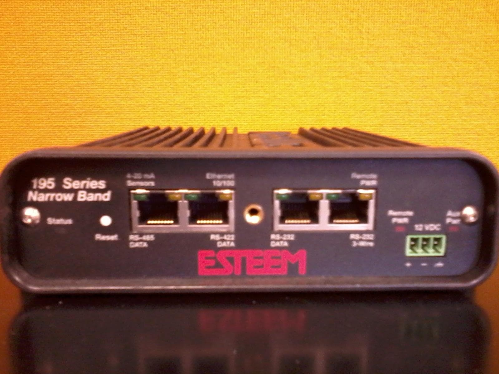
ENPESTEEM195H
Aug 12, 2014217-220MHz VHF Telemetry Modem
Equipment Class
TNB - Licensed Non-Broadcast Station Transmitter
ENPESTEEM195C
Dec 19, 2013450-470MHz Narrow-band UHF modem
Equipment Class
TNB - Licensed Non-Broadcast Station Transmitter
ENPESTEEM210M
Sep 05, 2013Data radio modem
Equipment Class
TNB - Licensed Non-Broadcast Station Transmitter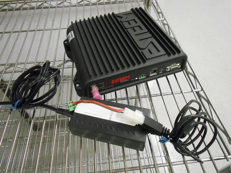
ENPESTEEM210C
Mar 10, 2013Data radio modem
Equipment Class
TNB - Licensed Non-Broadcast Station Transmitter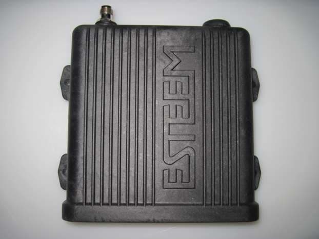
ENPESTEEM195EA
Feb 12, 2012Wireless LAN transceiver
Equipment Class
DTS - Digital Transmission System