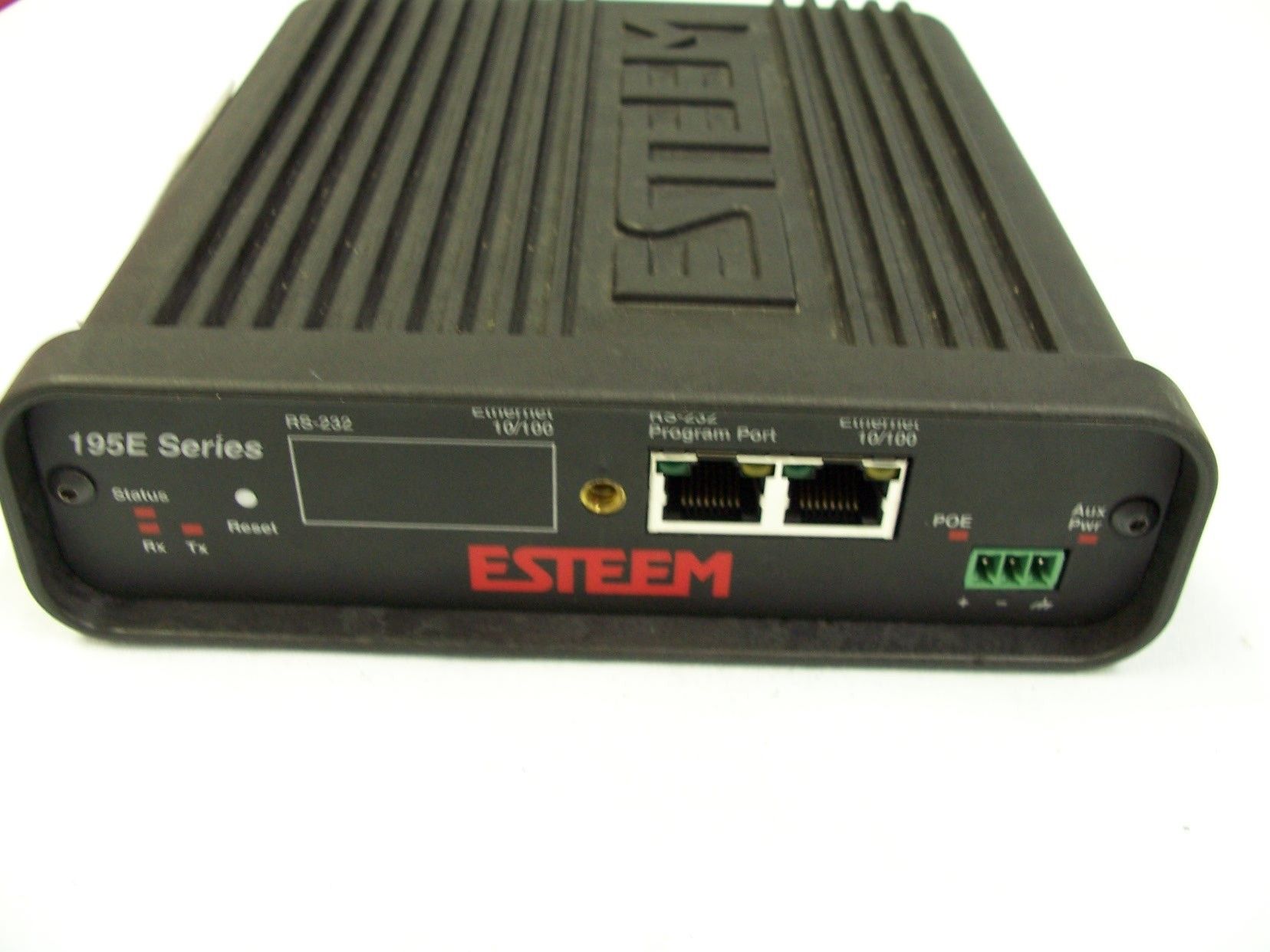
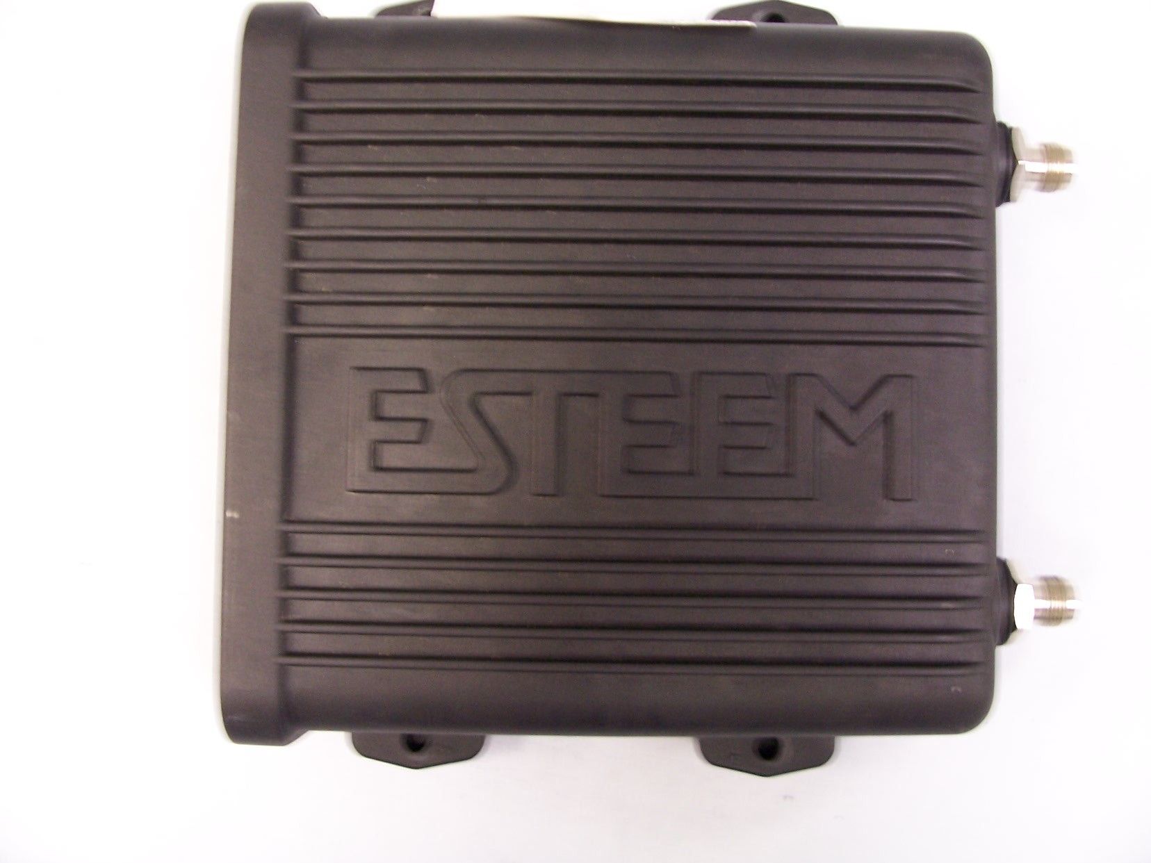
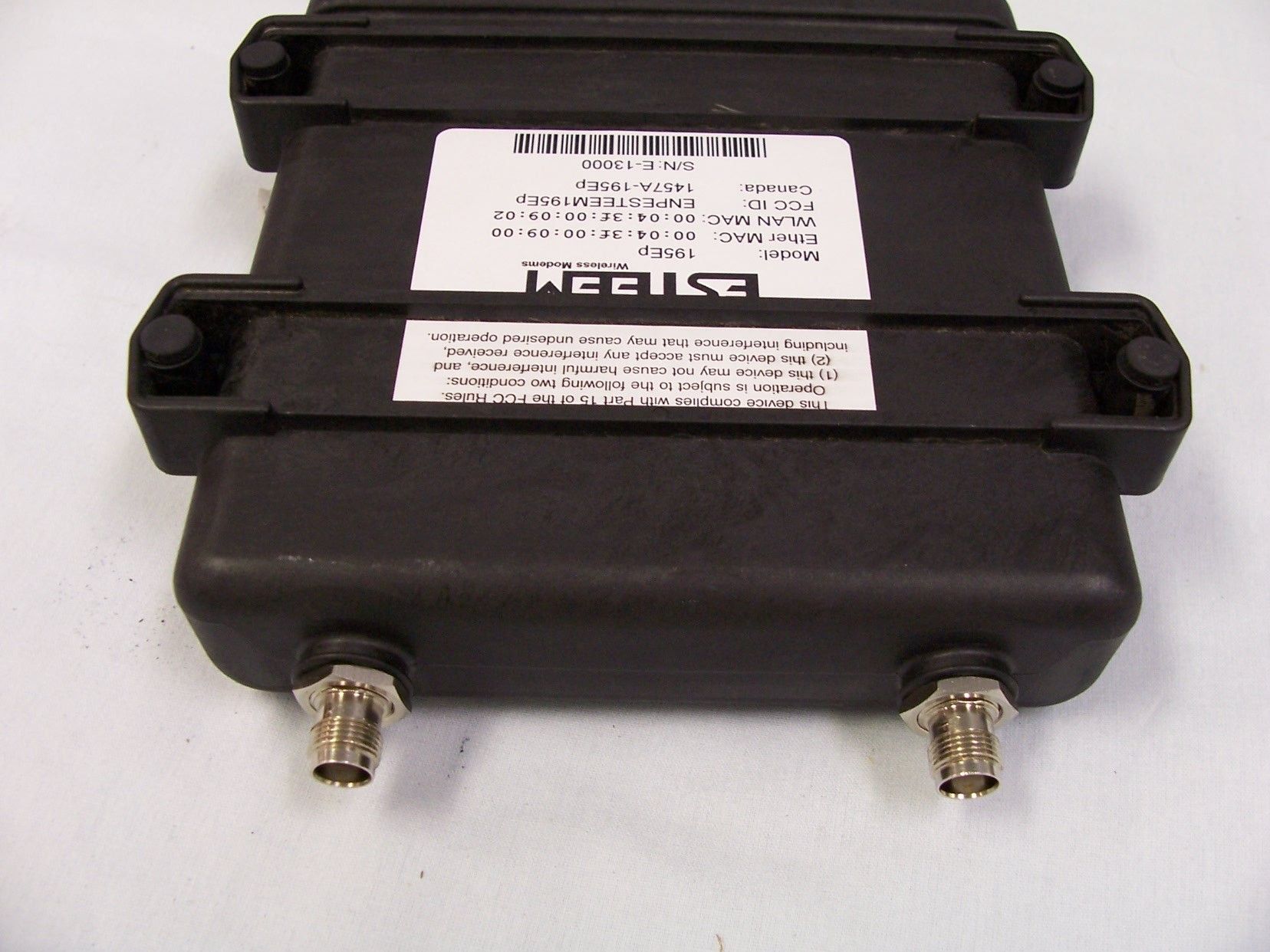
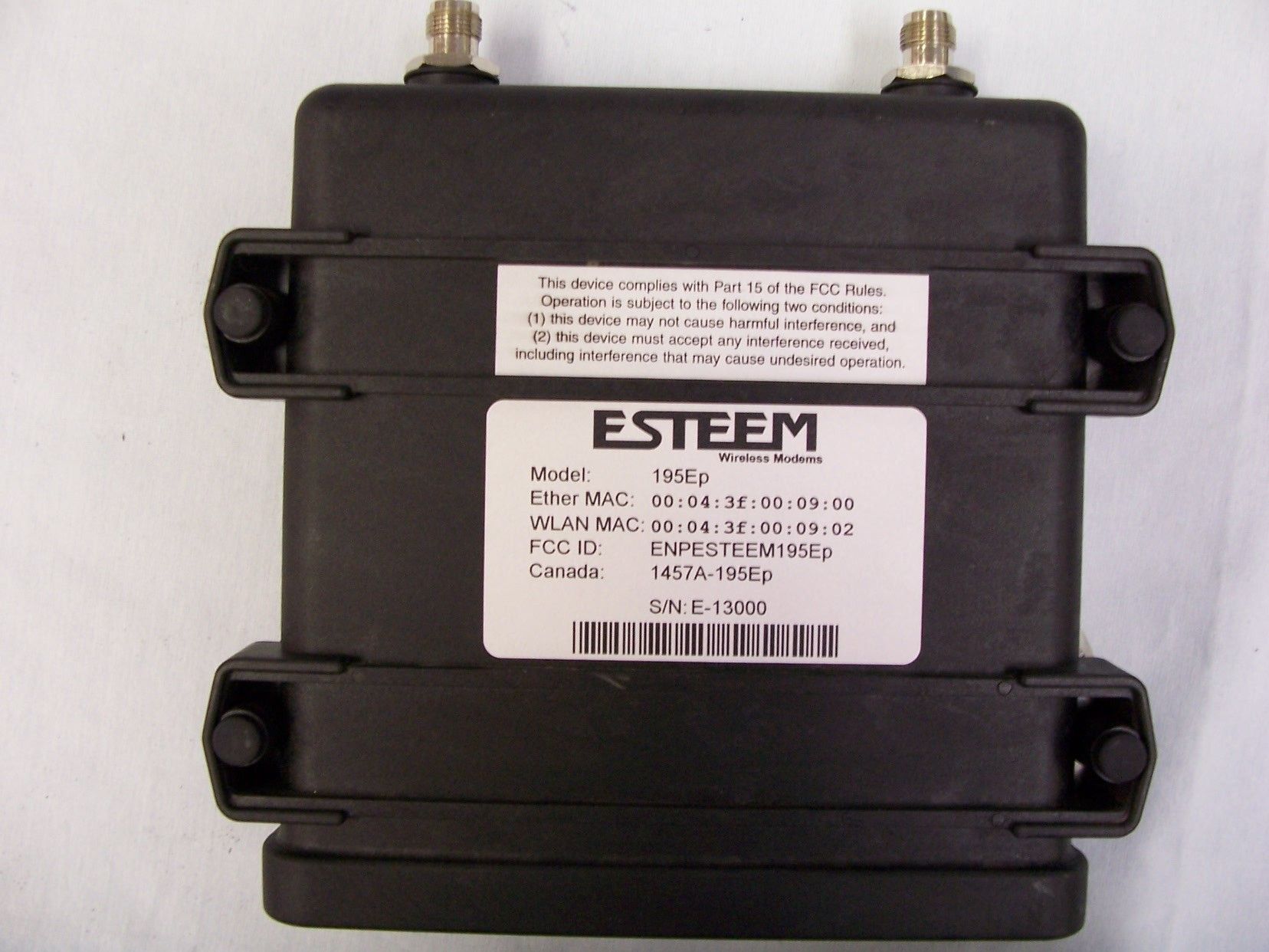
ENPESTEEM195EPBASE STATION TRANSMITTER
Electronic Systems Technology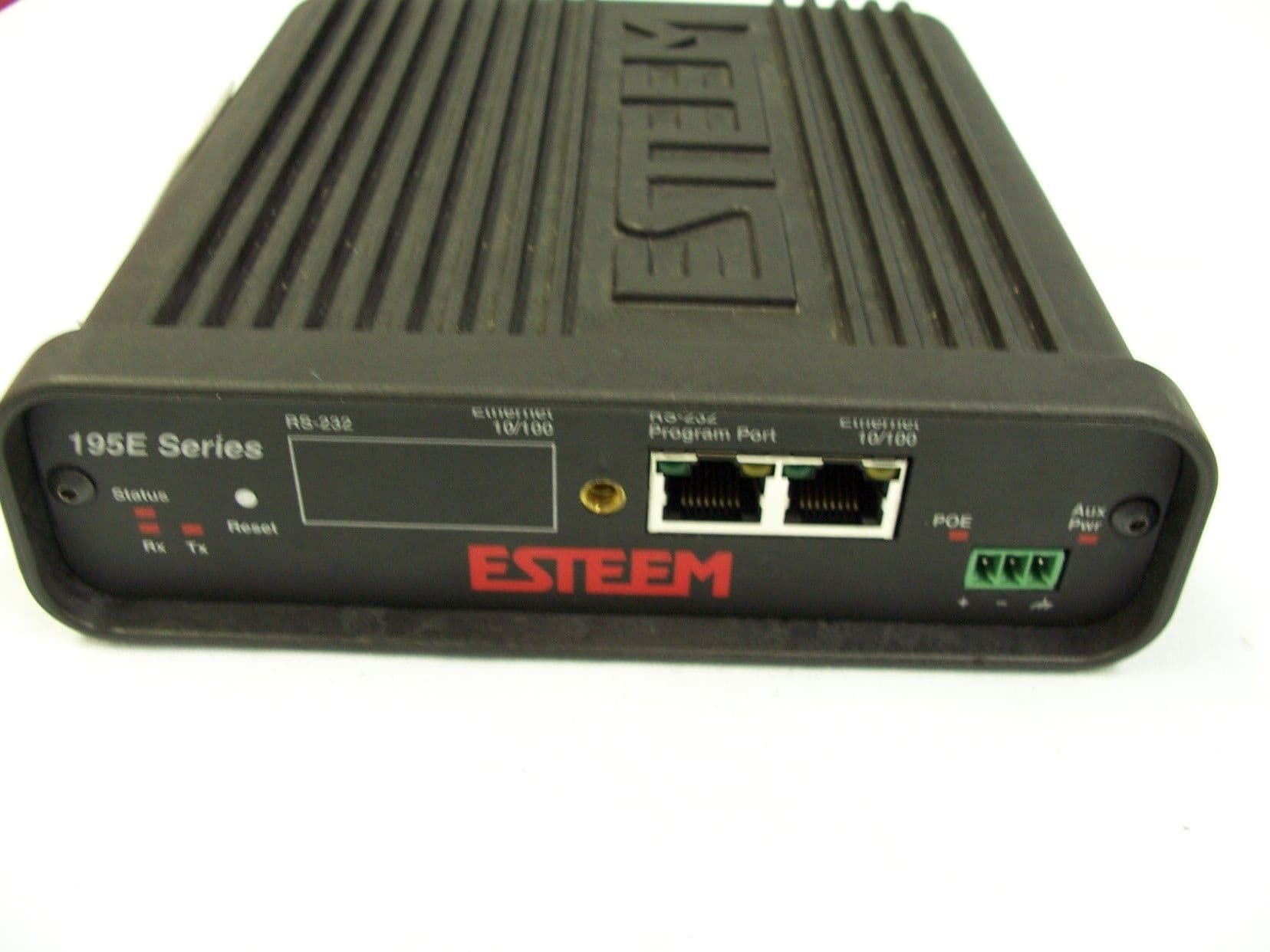
Click to zoom
Application Details
- Equipment Class
- TNB - Licensed Non-Broadcast Station Transmitter
- Date of Grant
- Aug 03, 2006
- Application Purpose
- Original Equipment
- Date of Application
- Aug 03, 2006
- Equipment Note
- BASE STATION TRANSMITTER
- Frequency Range
- 4960.00000000 - 4980.00000000
- Country
- United States
Documents & Files
Document Text
Text extracted from the exhibit documents filed with the FCC. Open a document above to read the original.
Users Manual
APPENDIX A FCC INFORMATION Revised: 16 Jun 06 APX A-1 EST P/N AA107P INFORMATION TO USERS Note to User: Changes or modifications to this equipment not expressly approved by Electronic Systems Technology for compliance could void the user's authority to operate the equipment. Other Information Model 195Ep Direct Sequence Spread Spectrum Device FCC Type Acceptance No: Canadian Certification Number: The equipment has been tested and found to comply with the limits for a Class A digital device, pursuant to Part 15 of the FCC Rules. These limits are designed to provide reasonable protection against harmful interference when the equipment is operated in a commercial environment. This equipment generates, uses, and can radiate radio frequency energy and, if not installed and used in accordance with the instruction manual, may cause harmful interference to radio communications. Operation of this equipment in a residential area is likely to cause harmful interference in which case the user will be required to correct the interference at his own expense. APPENDIX A FCC INFORMATION Revised: 16 Jun 06 APX A-2 EST P/N AA107P FEDERAL COMMUNICATIONS COMMISSION FIELD OFFICES ALASKA 1011 E. Tudor Rd. Rm 240 Box 2955 Anchorage, AK 99510 CALIFORNIA Interstate Office Park 4542 Ruffner St., Room 370 San Diego, CA 92111-2216 Los Angeles Office (LA) Ceritos Corporate Tower 18000 Studebaker Rd., Room 660 Cerritos, CA 90701-3684 San Francisco Office (SF) 5653 Stoneridge Drive, Suite 105 Pleasanton, CA 94588-8543 COLORADO Denver Office (DV) 215 S. Wadsworth Blvd., Suite 303 Lakewood, CO 80226-1544 FLORIDA 919 Federal Bldg 51 SE First Ave. Miami, FL 33130 Tampa Office (TP) 2203 N. Lois Ave., Room 1215 Tampa, FL 33607-2356 GEORGIA Atlanta Office (AT) 3575 Koger Blvd., Suite 320 Duluth, GA 30096-4958 HAWAII 7304 Prince Kuhi Federal Building Honolulu, HI ILLINOIS Chicago Office (CG) Park Ridge Office Ctr., Room 306 1550 Northwest Highway Park Ridge, IL 60068-1460 LOUISIANA New Orleans Office (OR) 2424 Edenborn Ave. Suite 460 Metarie, LA 70001 MARYLAND 1017 Geo. Fallon Building 31 Hopkins Plaza Baltimore, MD MASSACHUSETTS Boston Office (BS) 1 Batterymarch Park Quincy, MA 02169-7495 MICHIGAN Detroit Office (DT) 24897 Hathaway Street Farmington Hills, MI 48335-1552 MINNESOTA 691 Federal Building 316 N Robert St. St. Paul, MN MISSOURI Kansas City Office (KC) 520 NE Colbern Road Second Floor Lee’s Summit, MO 64086 NEW YORK 1307 Federal Building 111 W. Huron Buffalo, NY 14202 NEW YORK New York Office (NY) 201 Varick Street, Suite 1151 New York, NY 10014-4870 OREGON 1782 Federal Building 1220 SW 3rd Avenue Portland, OR 97204 PENNSYLVANIA Philadelphia Office (PA) One Oxford Valley Office Bld. Room 404 2300 E. Lincoln Hwy Langhorne, PA 19047-1859 PUERTO RICO 747 Federal Building Carlo Chardon Ave. Hato Rey, PR 00918 TEXAS Dallas Office (DL) 9330 LBJ Freeway, Room 1170 Dallas, TX 75243-3429 5636 Federal Building 515 Rusk Avenue Houston, TX 77002 WASHINGTON DC Columbia Office (CF) 9300 East Hampton Drive Capitol Heights, MD 20743 WASHINGTON Seattle Office (ST) 11410 NE 122 nd Way Room 312 Kirkland, WA 98034-6927
Users Manual
APPENDIX B SPECIFICATIONS Model 195Eg Specifications Revised: 16 Jun 06 APX B-1 EST P/N AA107P LED Indicators Power On/Off Receiver On/Off Carrier Detect On/Off Transmitter On/Off Link Status On/Off I/O Connectors Ethernet 10/100Base T RJ-45 RS-232C Programming Port RJ-45 Dual Antenna input/Outputs TNC Reverse Female Direct Input Power Header Screw Connector Transmiter Frequency of Operation 4.960 & 4.980 GHz Software Selectable with two Channels RF Data Rates 1,2,5.5,6,9, & 11 Mbps Fixed or Auto Scaling DSSS/CCK Modulation Tx Output Power 2 Watts (peak) / 1 watt (average) RF Output Impedance 50 ohms Receiver Rx Sensitivity -85 dBm @11 Mbps to –92 dBm @ 1 Mbps Frame Error Rate <10% Power Power Connector on Unit 10 to 16 VDC Receive 320 ma @ 12 VDC Transmit 1500 ma @ 12 VDC Case Dimensions 1.9 in. H x 6.7 in. W x 6.2 in. L Weight 1.25 lbs. Outdoor Pole Mounting Kit Optional, EST P/N 195PM Other Warranty 1 Year Temperature Range -30° to +60° C Humidity 95% Non-condensing FCC Type Acceptance Pending Type Acceptance Specifications Subject to Change Without Notice APPENDIX B SPECIFICATIONS Model 195Eg Case Specifications Revised: 16 Jun 06 APX B-2 EST P/N AA107P APPENDIX B SPECIFICATIONS Antenna Specifications Revised: 16 Jun 06 APX B-3 EST P/N AA107P Model No: AA191Ep Antenna Type: Omni-Directional, Vehicle Mount Applications: Mobile Model AA191Ep Frequency: 4.9-5.0 GHz Polarization: Vertical Caution Omni-directional antenna should not be located within 20 cm of personnel. Impedance: 50 ohms Gain: 5.5 dBi VSWR: < 1.5 Front to Back Ratio: n/a Horizontal Beamwidth: n/a Vertical Beamwidth: n/a Antenna Material: Black Radome Mounting Hardware: Base Included Antenna Connector: TNC-R Male Antenna Envelope: 12 in. length by 1.75 in width Weight: .08 lbs. Model: AA20DMEp Model AA20DMEp Applications: Model 195Ep direct case mount Antenna Type: Omni-Directional, Sleeve dipole Frequency: 4.9-5.0 GHz Caution Omni-directional antenna should not be located within 20 cm of personnel. Polarization: Vertical Impedance: 50 ohms Gain: 5.5 dBi (3.5 dBd) VSWR: < 2:1 Power: 10 W Front To Back Ratio: n/a Horizontal Beamwidth: n/a Vertical Beamwidth: n/a Antenna Material: Polyurethane Plastic Radome Recommended Mounting Hardware: n/a Antenna Connector: TNC-R Male Flexibility: +/- 20 ° Antenna Envelope: 8.28 in. length by .54 in. width Temperature: -40 to +70 C° Weight: 33 grams APPENDIX B SPECIFICATIONS Antenna Specifications Revised: 16 Jun 06 APX B-4 EST P/N AA107P Mounting Bracket Model AA20Eg Caution To comply with the FCC exposure compliance requirements, a separation distance of at least 20 cm must be maintained between the antenna and all persons. Model No: AA20Ep Antenna Type: Omni Directional, DC Grounded Applications: Fixed base Frequency: 4.9-5.0 GHz Polarization: Vertical Impedance: 50 ohms Gain: 9 dBi (7dBd) VSWR: 1.2:1 Typical Front to Back Ratio: n/a Horizontal Beamwidth: n/a Vertical Beamwidth: 40 degrees @ ½ power Antenna Material: Brass radiator, UV inhibited fiberglass enclosed Mounting Hardware: Base to Mast, Supplied. Antenna Connector: TNC-R Male with 36in. pig-tail. Antenna Envelope: 12 in. length by 1 in. diameter Weight: 1.5 lbs. APPENDIX B SPECIFICATIONS Antenna Specifications Revised: 16 Jun 06 APX B-5 EST P/N AA107P Model No: AA203Ep Caution To comply with the FCC exposure compliance requirements, a separation distance of at least 20 cm must be maintained between the antenna and all persons. Antenna Type: Directional, DC grounded Applications: Fixed base. Frequency: 4.9-5.0 GHz Polarization: Vertical or Horizontal Impedance: 50 ohms Gain: 9 dBi (7 dBd) VSWR: < 1.5 Model AA203Ep Front to Back Ratio: 23 dB Horizontal Beamwidth: 55 degrees @ ½ power Vertical Beamwidth: 55 degrees @ ½ power Antenna Material: Sealed in UV stable fiberglass enclosed radome Mounting Hardware: Stainless steel U bolts (included) for mounting up to 1 5/8 in. diameter pipe. Antenna Connector: TNC-R Male with 36in. pig tail Maximum Power Input: 5 Watts Antenna Envelope: 4.5 in. length by 3 in. diameter Windload (RWV): 125 mph Lateral Thrust at Rated Wind: 5.8 lbs. Wind Surface Area: 0.060 ft 2 Weight: 1 lbs. APPENDIX B SPECIFICATIONS Antenna Specifications Revised: 16 Jun 06 APX B-6 EST P/N AA107P Model No: AA204Ep Applications: Fixed base mounting Antenna Type: 2.4 GHz ISM, Directional, DC Grounded, Parabolic Grid Frequency: 4.9-5.0 GHz Polarization: Vertical or Horizontal Caution To comply with the FCC exposure compliance requirements, a separation distance of at least 50 cm must be maintained between the antenna and all persons. Impedance: 50 ohms Gain: 26 dBi (24 dBd) nominal VSWR: < 1.5:1 nominal Front to Back Ratio: >24 dB Horizontal Beamwidth: 16 degrees @ ½ power Vertical Beamwidth: 11 degrees @ ½ power Antenna Material: Zinc plated cold rolled steel with polyester power coat finish Model AA204Eg Recommended Mounting Hardware: Standard U-bolt steel mast clamp complete with mounting hardware. Designed for masts of up to 2.5 in. O.D. Antenna Connector: TNC-R Male with 36 in. pig-tail Maximum Power Input: 10 Watts Wind Survival: 100 mph Wind Load: 16 mph Antenna Envelope: 34 in. length by 17 in. width by 11 in. height Weight: 3 lbs.
Users Manual
APPENDIX D RADIO CONFIGURATION Revised: 16 Jun 06 APX D-1 EST P/N AA107P 195Ep FREQUENCY OF OPERATION In a wireless Ethernet network all of the ESTeem Model 195Ep’s must be set to the same radio frequency of operation or channel. The frequency of operation is selectable when configuring the mode of operation of the 195Ep (reference Chapter 4). See Figure 1. Figure 1: RF Channel Selection RF COMMUNICATIONS DATA RATE The RF data rate of the Model 195Ep can be programmed for operation at 1, 2, 5.5, or 11 Mbps. The RF data rate can be set for a fixed rate or a specific range that is dynamically scaled by the Model 195Ep from monitoring the received signal quality. By selecting all ranges from 1 to 11 Mbps you will be able to communicate with all mobile or remote locations devices regardless of their signal strength. Dynamic scaling means that the Model 195Ep will operate at the highest RF data rate that is programmed into unit. If the received data quality drops below the required minimums for reliable communications the Model 195Ep will reduce the data rate to the next lowest step to increase signal quality. Conversely if the signal quality increases above the minimums the Model 195Ep will increase the RF data rate the next highest level. The ESTeem 195Ep is set at the factory to operate at maximized scaling speed data rates from 1-11 Mbps and should not need adjustment. The RF Data Rate is programmed in the Model 195Ep through the Advanced Menu>Wireless LAN Settings>Wlan0 Device and the value for wlan0_OPRATES:. In the example shown in Figure 2 the RF Date Rate is programmed to dynamic scale from 1 to 11 Mbps (recommend factory default setting). To set the values for the data rate, check the box next to the listed data rate to enable this rate for operation. APPENDIX D RADIO CONFIGURATION Revised: 16 Jun 06 APX D-2 EST P/N AA107P RF BASIC RATE Figure 2: Advanced Data Rate Selection The RF Basic Rate is the synchronization rate used to establish the initial connection between 802.11g and 802.11b communication devices in Mbps. After the initial connection has been establish the RF communication rate will be determined by the RF Communication Data Rate established above. Factory default is 1 through 11 Mbps shown in Figure 2 so that the unity will establish communication with the older (slower) 802.11b devices. This lower rate also allows for a quicker reconnect when the ESTeems are configured for EtherStation mode or working in a mobile environment. The ESTeem 195Ep is set at the factory to operate at all speeds from 1-11 Mbps and should not need adjustment. The RF Basic Rate is programmed in the Model 195Ep through the Advanced Menu>Wireless LAN Settings>Wlan0 Device and the value for wlan0_AP_BASICRATES:. In the example shown in Figure 2 the RF Date Rate is programmed to dynamic scale from 1 to 11 Mbps (recommend factory default setting). To set the values for the data rate, check the box next to the data rate required. Note: The Model 195Ep will only communicate with slower speed devices after synchronization if the RF Communication Data shown above has been set to dynamically scale to 1 and 2 Mbps. In general, do not set the RF Basic Rates above 11Mbps unless specifically instructed by ESTeem Customer Support.
Users Manual
APPENDIX E SECURITY Revised: 1 Aug 05 APX E-1 EST P/N AA107G OVERVIEW The security for the ESTeem Model 195Eg, like all network security, must be multi-layered. One level of security is never enough to make sure that data does not end up in the wrong hands. Please review the following security levels and decide what is the most appropriate for your network. 128-BIT WEP The 128 WEP uses a particular algorithm called RC4 encryption to encode and decode traffic that is based on a 104-bit encryption key and a 24-bit Initialization Vector (IV). RC4 starts with a relatively short encryption key (104 bits) that is expanded into a nearly infinite stream of keys to accompany the stream of packets. The basic concept of RC4 is good, but the way it’s implemented in WEP leaves it open to compromise. The researchers that test the integrity of the system usually focus on one piece of the implementation, the Initialization Vector (IV). The IV (24 bits) is the algorithm component that’s supposed to keep expanded keys from repeating. From the researcher’s point of view, a high-volume access point is mathematically guaranteed to reuse the same key stream at least once a day. When this happens, it’s called an IV collision this becomes a soft spot to enter the system. The researchers aren’t saying that it’s easy to break into the system, or that it’s being done on a regular basis, only that it is possible and that administrators should consider ways to reduce the possibility. WPA Wi-Fi Protected Access with Preshared Key (WPA PSK) WPA, which uses 802.1x, was introduced in 2003 to improve on the authentication and encryption features of WEP. All authentication is handled within this access point device. WPA has two significant advantages over WEP: 1. An encryption key differing in every packet. The TKIP (Temporal Key Integrity Protocol) mechanism shares a starting key between devices. Each device then changes their encryption key for every packet. It is extremely difficult for hackers to read messages even if they have intercepted the data. 2. Certificate Authentication (CA) can be used, blocking a hacker posing as a valid user. Wi-Fi Protected Access with Enterprise Server (WPA Enterprise) Like WPA PSK, WPA Enterprise uses 802.1x. However, a backend authentication server handles the authentication decision. The most commonly type of authentication server is a RADIUS server. The ESTeem Model 195Eg can be configured to operate with an established RADIUS server on the network. WPA is server/client relationship from a software driver on a computer’s wireless LAN (WLAN) card to an Access Point. The scope of WPA is limited in use to this configuration only. The ESTeem Model 195Eg can support WPA Enterprise and PSK as an Access Point, but the level of security on the Bridging layer is configured separately. ACCESS CONTROL LIST (ACL) The ACL is one of the simplest yet most secure methods of network security. The ACL is a configurable MAC filter in the Model 192E that can be set to allow specific MAC address on the wireless network by individual address or address ranges. The same filter can also be set to reject individual MAC addresses or address ranges. The MAC address is a unique, 6 hexadecimal field address assigned at the manufacturer that can not be changed. The MAC address is traceable through the IEEE governing body to the manufacturer and is the “fingerprint” for all Ethernet devices. APPENDIX E SECURITY Revised: 1 Aug 05 APX E-2 EST P/N AA107G Using a combination of both the WPA or 128-Bit WEP encryption and the ACL filter provide the ESTeem an extremely secure wireless networking layer. DISABLING BROADCAST PROBES AND HIDING SSID A simple but very effective way of securing a network is to make the network difficult to find. By disabling broadcast probes and hiding the Service Set Identification (SSID), wireless and network “sniffers” will not be able to find your ESTeem Model 195Eg network. To gain access to the wireless network, you would be required to have the SSID and all security loaded in the WLAN card software prior to entering the network. PROPRIETARY BRIDGE COMMUNICATION Although the ESTeem Model 195Eg is compatible with the open communication standards IEEE 802.11g and 802.11b, the repeater communication between the units is a proprietary communication link. No other manufacturer of wireless hardware can access the ESTeem repeater network when bridging between Ethernet networks. This proprietary communication layer, in combination with the other security settings, allows you as the user to reject wireless clients into the network if so desired. When used in conjunction with the Access Control List the 802.11g and 802.11b client access can be removed. The security level of the bridge communication link is configurable for 64-Bit WEP, 128-Bit WEP or TKIP and is completely independent of the client access level or any other communication link level. For example, an ESTeem Model 195Eg can be configured for WPA Enterprise for client level access, communicate to another ESTeem Model 195Eg using a TKIP bridge link and also communicate 128-Bit WEP to our older ESTeem Model 192E radio modems all running simultaneously. MASQUERADE MODES When the ESTeem Model 195Eg is configured in either the Access Point Masquerade or the Client Masquerade modes, the wireless modem functions as a network firewall. If access to the wired network is the greatest concern, place the ESTeem in the Masquerade mode and the wireless network will be completely isolated from the wired Ethernet network. INCREASING NETWORK SECURITY The following are a few suggestions to help improve the overall security of your wireless network: 1. Enable the security. If you research all of the articles regarding hackers, they have gotten into the user’s network due to the security not being enabled. 2. Set the ACL filter to include only those MAC address of the wireless Ethernet device being used on the network. 3. Set "Hide SSID" to True. As you ta…
Text truncated - open the document above for the full version.
Users Manual
APPENDIX F TROUBLESHOOTING Revised: 16 Jun 06 APX F-1 EST P/N AA107P TESTING COMMUNICATION LINK After you have configured at least two of the Model 195Ep wireless Ethernet modems for operation, you can verify communication with each the following steps: Status Light The quickest source of link status is to view the Status Light on the face of the 195Ep (Figure 1). If the Status light is solid, the Model 195Ep has a connection to another Model 195Ep listed in the Peer Table. Status Screen/Peer Table To view detailed information on the status of the communication link (such as connection speed, signal strength and last update time) you can open the Status Screen from the Web Interface. After press the Status tab at the top of the screen the Status: Summary will be displayed showing the status of all ports and memory in the 195Ep. Under the Wireless Status heading click on the View Peer Table (Figure 2). The Peer Table will list all other 802.11b or 802.11g wireless activity seen by the 195Ep and how it is classified. Status LED Solid Red on Link Figure 1: Connection Status Light Opposite Modem’s Wireless MAC Receive Signal Strength (dBm) Last Packet Received Peer Modem ID Other Access Points Figure 2: Repeater Peer Table Note: The data rate displayed is not necessarily indicative of the RF data rate between the ESTeems. The rate show in the Repeater Peer table will be the last RF packet, which could consist of either data, repeater beacon or network probes. APPENDIX F TROUBLESHOOTING Revised: 16 Jun 06 APX F-2 EST P/N AA107P Repeater Peers - The Peer Table will display all connected 195Eps configured to repeat to this ESTeem by their Wireless (WLAN) MAC address. Received Signal Strength – This is the first of the two numbers listed in the block. This signal strength value is listed in dBm. Last RX – This is the time of the last received data packet. When monitoring the status menu, it is important to note the time the last transmission was updated so you are not looking at “stale” data. Current Data Rate – This is the current speed the last data packet received by the Model 195Ep. This may not be the data rate between the radio modems. Note that the speed is listed in kbps, so that 11000 kbps is equal to 11 Mbps. Note: The ESTeem Model 195Ep uses spread spectrum technology that analyzes each data packet for signal strength and data quality (strength vs. noise). The higher your signal, the mare background noise you can sustain without causing degradation in the data transfer. This is also true for lower signal strengths with a very low background noise. These values are provided for guidance and if you have any questions about the values in your application, please contact ESTeem Customer Support at 509- 735-9092 or e-mail your application to [email protected]. Modem ID – This is Modem ID for the opposite repeater peer. Figure 3: Peer Summary Table Viewing RF Data Rates The value shown on the Peer Status Screen for data rate may not be the actual rate of the RF link. To view the link information, click on the Opposite Modems WLAN MAC address in the Repeater Peer list (Figure 2) and further link status information will be displayed (Figure 3). Once loaded, click on View Peer Rate Control Information. (Figure 4) APPENDIX F TROUBLESHOOTING Revised: 16 Jun 06 APX F-3 EST P/N AA107P Figure 4: Rate Control Information The value of the Current TX rate is the RF data rate between the two ESTeem Model 195Ep. ETHERSTATION STATUS PROGRAM When configured for EtherStation mode, the Web Configuration Manger is turned off. To gather information from the 195Ep on Access Point, link status and received signal strength you will need to install the ESTeem 195E Status Utility. This software program is found on the AA109 Resources Disk or available from the ESTeem web site. To install the utility, please complete the following: ESTEEM DISCOVERY UTILITY The ESTeem Discovery Utility will allow you to configure the IP address on the Model 195Ep to match your network. Install the Discovery Utility on your computer by inserting the Resource Disk in your CD drive. Note: The ESTeem Resource Disk is stand-alone copy of the ESTeem Web site (Figure 5). Navigation of the Resource Disk is as simple as using your web browser. All technical documentation, User’s Manuals and the ESTeem Utility Program is available on the disk. Figure 5: ESTeem Resource Main Page 1. Place the ESTeem Utility CD in your CD-ROM drive. The CD will auto load the ESTeem main page APPENDIX F TROUBLESHOOTING Revised: 16 Jun 06 APX F-4 EST P/N AA107P Note: If the page does not auto load, open your web browser and set your address line to D:\1_default.html (Where D: is the drive letter for your CD-ROM drive). Figure 6: Discovery Utility Download 2. From the Main Page select ESTeem Utilities and click on Download EtherStation Status Utility Note: This program is saved in a compressed file format. Microsoft Windows XP® will open the file directly, but other operating systems will require a common compression program such as WinZip available for download at http://www.winzip.com 3. Double click on the 195EStatusSetup.exe file listed in the window to install the program. 4. Connect the Model 195Ep to your computer either direct to the Ethernet card or through a HUB/Switch using a CAT-5e Ethernet cable. The Ethernet port on the 195Ep supports Auto-Negotiation so either a patch cable or crossover cable will work. Open the ESTeem Status Program and a status icons will appear in your system tray (Figure 7). When the status menu is opened from the system tray, the status window will be displayed (Figure 7) to show the Access Point MAC address and signal strength. The tray icon and Signal Strength bar will display the colors from Green, Yellow to Red on progressivly poorer signal or will show Grey if roaming. Figure 7: EtherStation Status Program Note: This Utility will only operate with an ESTeem Model 195Ep in EtherStation mode. APPENDIX F TROUBLESHOOTING Revi…
Text truncated - open the document above for the full version.
Users Manual
ESTeem MODEL 195Ep USER’S MANUAL Manual Revision 1.0 June 2006 Electronic Systems Technology, Inc. ESTeem MODEL 195Eg USER’S MANUAL Manual Revision 1.0 Firmware Version 302.6 and above June 2006 Prepared by: Date: Name: Eric P. Marske Title: Product Manager Approved by: Date: Name: Tom L. Kirchner Title: President COPYRIGHT INFORMATION This manual and the firmware described in it are copyrighted by EST, with all rights reserved. Under the copyright laws, this manual or the firmware internal to the ESTeem unit may not be copied, in whole or part, without the written consent of EST. Under the law, copying includes translating into another language. Electronic Systems Technology (EST) cannot guarantee that you will receive notice of a revision to the firmware described in the manual, even if you have returned a registration/warranty card received with the product. You should periodically check with your authorized EST dealer or call factory direct. EST and the EST logo are registered trademarks of Electronic Systems Technology, Inc. Simultaneously published in the United States and Canada. All rights reserved. WARRANTY INFORMATION Electronic Systems Technology, Inc., (hereinafter EST) expressly warrants its products as free of manufacturing defects for a period of one year from the date of sale to first user/customer. THERE ARE NO OTHER WARRANTIES, EXPRESS OR IMPLIED AND THERE IS EXPRESSLY EXCLUDED ALL WARRANTIES OF MERCHANTABILITY OR FITNESS FOR A PARTICULAR PURPOSE. NO OTHER WARRANTY GIVEN BY ANY EMPLOYEE, AGENT, DISTRIBUTOR OR OTHER PERSON WITH RESPECT TO THE PRODUCT SHALL BE BINDING ON EST. LIMITATION OF LIABILITY: EST's liability shall be limited to refunding of purchase price, repair or replacement of product. IN NO EVENT SHALL EST HAVE LIABILITY FOR CONSEQUENTIAL, INCIDENTAL, SPECIAL OR EXEMPLARY DAMAGES CAUSED DIRECTLY OR INDIRECTLY BY THE PRODUCT, INCLUDING BUT NOT LIMITED TO ANY INTERRUPTION OF SERVICES, LOSS OF BUSINESS OR ANTICIPATORY PROFITS. IN NO EVENT SHALL EST BE LIABLE FOR ANY DAMAGES WHATSOEVER IN EXCESS OF THE PURCHASE PRICE OF THE PRODUCT. In the event that a unit or part requires replacement or factory servicing, the following conditions apply: a) Customer must obtain from EST an authorized RMA (Return Materials Authorization) number (call 509-735-9092 Customer Support) before shipment of product or parts to EST for any reason; b) If the whole unit is shipped, it must be in its original carton and shipping components, or a carton and shipping components supplied by EST, or if parts only are shipped, they must be packaged and cushioned so as to prevent damage in transit and shipped freight prepaid; PRODUCT WILL BE CONSIDERED OUT OF WARRANTY IF: a) If the product is damaged due to improper or abnormal use, abuse, mishandling, accident or improper maintenance or failure to follow operating instruction; b) If the product is defective as a result of sand, dirt, or water damage; c) If any factory-sealed enclosure has been opened or shows evidence of an attempt to be opened; d) If defects or damage are caused by the use of unauthorized parts or unauthorized service; e) If the product has had its serial numbers altered or removed. Warranty repair form must be accompanied by proof of user's purchase of unit. Product must be shipped to the manufacturer at the following address: Electronic Systems Technology 415 North Quay Street Building B-1 Kennewick, Washington USA 99336 ADDITIONAL SERVICE: If EST releases an improvement update to firmware internal to the ESTeem unit during the 90 day period after the unit was purchased by the first user/customer, EST will update the applicable unit with the revised version at no charge other than for UPS handling and shipping to and from your location to the EST factory. Return of any such item must be accompanied with proof of purchase.
Users Manual
TABLE OF CONTENTS Revised: 15 Jun 06 Page 1 EST P/N AA107P CHAPTER 1 – INTRODUCTION Before You Begin 1-1 Model 195Ep Overview 1-1 Model 195Ep Configuration Modes 1-1 Access Point Modes ---------------------------------------------1-2 Access Point Repeater ---------------------------------------------1-3 Self-Healing Mesh Network ---------------------------------------------1-3 Station (802.11g Client) Modes ---------------------------------------------1-3 CHAPTER 2 – CONFIGURATION DIAGRAMS Model 195Ep Access Point Configurations 2-1 Figure 1: Single Access Point Bridge Diagram ---------------------------------------------2-1 Figure 2: Multiple Access Point Bridge Diagram ---------------------------------------------2-1 Figure 3: Access Point Router Diagram ---------------------------------------------2-2 Figure 4: Access Point Masquerade Diagram ---------------------------------------------2-2 Model 195Ep Access Point Repeater with Clients Configurations 2-3 Figure 5: Access Point Bridge Repeater with Clients Diagram ---------------------------------------------2-3 Figure 6: Access Point Router Repeater with Clients Diagram ---------------------------------------------2-3 Figure 7: Access Point Masquerade Repeater with Clients Diag. ---------------------------------------------2-4 Model 195Ep Building to Building Configurations 2-4 Figure 8: Building to Building Configuration Diagram ---------------------------------------------2-4 Figure 9: Building to Building with Repeater Diagram ---------------------------------------------2-5 Figure 10: Building to Building Router Diagram ---------------------------------------------2-5 Model 195Ep Complete Wireless Solutions 2-6 Figure 11: Complete Bridge Network Solutions Diagram ---------------------------------------------2-6 Figure 12: Complete Router Network Solutions Diagram ---------------------------------------------2-7 CHAPTER 3 – STARTING OUT Overview 3-1 Quick Start Guide ---------------------------------------------3-1 Model 195Ep Hardware Layout 3-1 Required Hardware ---------------------------------------------3-1 Front Panel Overlay Diagram ---------------------------------------------3-2 Antenna Port Overview ---------------------------------------------3-2 Antenna Configuration ---------------------------------------------3-3 Hardware Configuration Diagram ---------------------------------------------3-3 System Configuration Table ---------------------------------------------3-4 ESTeem Discovery Utility 3-5 Installation ---------------------…
Text truncated - open the document above for the full version.
Contact Information
Applicant
Todd Elliott(Engineer)
Test Firm
Nemko USA, Inc.Tom Tidwell
Technical Specifications
| # | Rule Parts | Frequency Range | Power Output | Emission | Tolerance |
|---|---|---|---|---|---|
| 2 | 9 | 4.96 GHz - 4.98 GHz | 1.2 W | 16M6W7D | 1.2 ppm |
Other Applications from Electronic Systems Technology
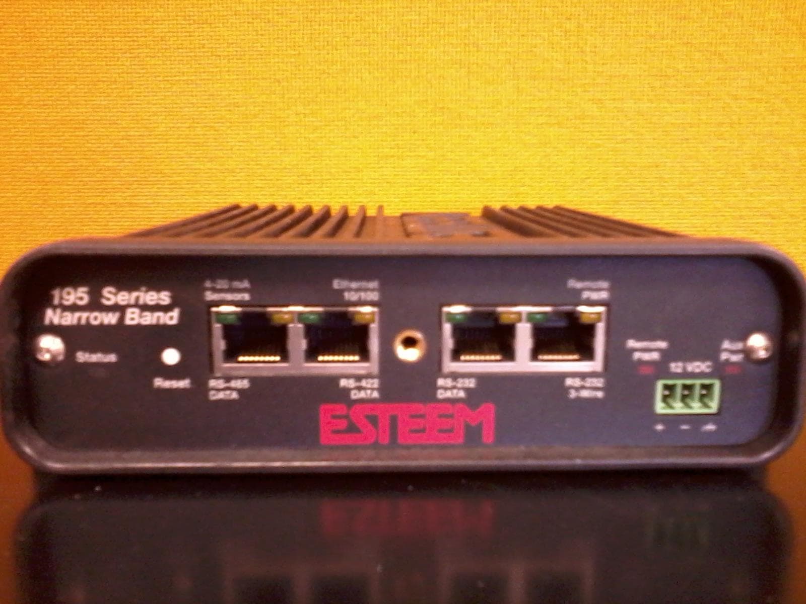
ENPESTEEM195H
Aug 12, 2014217-220MHz VHF Telemetry Modem
Equipment Class
TNB - Licensed Non-Broadcast Station Transmitter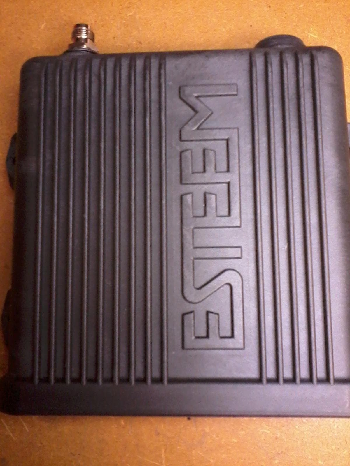
ENPESTEEM195C
Dec 19, 2013450-470MHz Narrow-band UHF modem
Equipment Class
TNB - Licensed Non-Broadcast Station Transmitter
ENPESTEEM210M
Sep 05, 2013Data radio modem
Equipment Class
TNB - Licensed Non-Broadcast Station Transmitter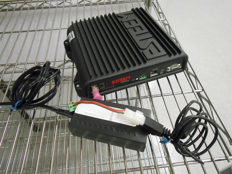
ENPESTEEM210C
Mar 10, 2013Data radio modem
Equipment Class
TNB - Licensed Non-Broadcast Station Transmitter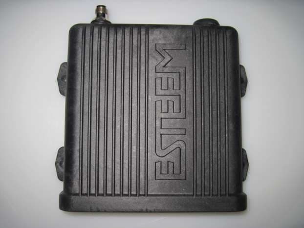
ENPESTEEM195EA
Feb 12, 2012Wireless LAN transceiver
Equipment Class
DTS - Digital Transmission System