ENPESTEEM195ESWireless Ethernet Radio Modem
Electronic Systems Technology
Click to zoom
Application Details
- Equipment Class
- DSS - Part 15 Spread Spectrum Transmitter
- Date of Grant
- Jun 05, 2007
- Application Purpose
- Original Equipment
- Date of Application
- Jun 05, 2007
- Equipment Note
- Wireless Ethernet Radio Modem
- Frequency Range
- 902.30000000 - 927.60000000
- Country
- United States
Documents & Files
Document Text
Text extracted from the exhibit documents filed with the FCC. Open a document above to read the original.
Users Manual
APPENDIX A REGULATORY INFORMATION Revised: 20 Feb 07APX A-1 EST P/N AA107S INFORMATION TO USERS The ESTeem Model 195Es complies with Part 15 of the FCC Rules. Operation is subject to the following two conditions: (1) This device may not cause harmful interference, and (2) this device must accept any interference received, including interference that may cause undesired operation. Note to User: Changes or modifications to this equipment not expressly approved by Electronic Systems Technology for compliance could void the user's authority to operate the equipment. Other Information Model 195Es Direct Sequence Spread Spectrum Device FCC ID No: ENPESTEEM195ES Canadian Certification Number: 2163A-195ES The equipment has been tested and found to comply with the limits for a Class A digital device, pursuant to Part 15 of the FCC Rules. These limits are designed to provide reasonable protection against harmful interference when the equipment is operated in a commercial environment. This equipment generates, uses, and can radiate radio frequency energy and, if not installed and used in accordance with the instruction manual, may cause harmful interference to radio communications. Operation of this equipment in a residential area is likely to cause harmful interference in which case the user will be required to correct the interference at his own expense. This device has been designed to operate with the antennas listed below, and having a maximum gain of 7 dBi. The antennas listed below with 7 dBi gain have permanently attached coaxial cables so that the rf power delivered to the antenna connector is less than 1 watt. Antennas not included in this list or having a gain greater than 6 dBi are strictly prohibited for use with this device. The required antenna impedance is 50 ohms. To reduce potential radio interference to other users, the antenna type and its gain should be so chosen that the equivalent isotropically radiated power (e.i.r.p.) is not more than that permitted for successful communication. The antennas should be mounted with a minimum separation distance as specified in APPENDIX B - SPECIFICATIONS. The antennas must not be co-located with other antennas. ANTENNA TYPE P/N. GAIN(dBi) Omni-Directional AA20DMEs 2 Omni-Directional Mag-Mount AA191Es 5 Omni-Directional DC Grounded AA20Es900 7 Yagi AA203Es900 7 APPENDIX A REGULATORY INFORMATION Revised: 20 Feb 07APX A-2 EST P/N AA107S FEDERAL COMMUNICATIONS COMMISSION FIELD OFFICES ALASKA 1011 E. Tudor Rd. Rm 240 Box 2955 Anchorage, AK 99510 CALIFORNIA Interstate Office Park 4542 Ruffner St., Room 370 San Diego, CA 92111-2216 Los Angeles Office (LA) Ceritos Corporate Tower 18000 Studebaker Rd., Room 660 Cerritos, CA 90701-3684 San Francisco Office (SF) 5653 Stoneridge Drive, Suite 105 Pleasanton, CA 94588-8543 COLORADO Denver Office (DV) 215 S. Wadsworth Blvd., Suite 303 Lakewood, CO 80226-1544 FLORIDA 919 Federal Bldg 51 SE First Ave. Miami, FL 33130 Tampa Office (TP) 2203 N. Lois Ave., Room 1215 Tampa, FL 33607-2356 GEORGIA Atlanta Office (AT) 3575 Koger Blvd., Suite 320 Duluth, GA 30096-4958 HAWAII 7304 Prince Kuhi Federal Building Honolulu, HI ILLINOIS Chicago Office (CG) Park Ridge Office Ctr., Room 306 1550 Northwest Highway Park Ridge, IL 60068-1460 LOUISIANA New Orleans Office (OR) 2424 Edenborn Ave. Suite 460 Metarie, LA 70001 MARYLAND 1017 Geo. Fallon Building 31 Hopkins Plaza Baltimore, MD MASSACHUSETTS Boston Office (BS) 1 Batterymarch Park Quincy, MA 02169-7495 MICHIGAN Detroit Office (DT) 24897 Hathaway Street Farmington Hills, MI 48335-1552 MINNESOTA 691 Federal Building 316 N Robert St. St. Paul, MN MISSOURI Kansas City Office (KC) 520 NE Colbern Road Second Floor Lee’s Summit, MO 64086 NEW YORK 1307 Federal Building 111 W. Huron Buffalo, NY 14202 NEW YORK New York Office (NY) 201 Varick Street, Suite 1151 New York, NY 10014-4870 OREGON 1782 Federal Building 1220 SW 3rd Avenue Portland, OR 97204 PENNSYLVANIA Philadelphia Office (PA) One Oxford Valley Office Bld. Room 404 2300 E. Lincoln Hwy Langhorne, PA 19047-1859 PUERTO RICO 747 Federal Building Carlo Chardon Ave. Hato Rey, PR 00918 TEXAS Dallas Office (DL) 9330 LBJ Freeway, Room 1170 Dallas, TX 75243-3429 5636 Federal Building 515 Rusk Avenue Houston, TX 77002 WASHINGTON DC Columbia Office (CF) 9300 East Hampton Drive Capitol Heights, MD 20743 WASHINGTON Seattle Office (ST) 11410 NE 122 nd Way Room 312 Kirkland, WA 98034-6927
Users Manual
TABLE OF CONTENTS CHAPTER 1 – INTRODUCTION Before You Begin 1-1 Model 195Es Overview 1-1 Model 195Es Configuration Modes 1-1 Access Point Modes ---------------------------------------------1-2 Access Point Repeater ---------------------------------------------1-3 Self-Healing Mesh Network ---------------------------------------------1-3 Station Modes ---------------------------------------------1-3 Serial Applications ---------------------------------------------1-4 CHAPTER 2 – CONFIGURATION DIAGRAMS Model 195Es Access Point Configurations 2-1 Figure 1: Single Access Point Bridge Diagram ---------------------------------------------2-1 Figure 2: Multiple Access Point Bridge Diagram ---------------------------------------------2-1 Figure 3: Access Point Router Diagram ---------------------------------------------2-2 Figure 4: Access Point Masquerade Diagram ---------------------------------------------2-2 Model 195Es Access Point Repeater with Clients Configurations 2-3 Figure 5: Access Point Bridge Repeater with Clients Diagram ---------------------------------------------2-3 Figure 6: Access Point Router Repeater with Clients Diagram ---------------------------------------------2-3 Figure 7: Access Point Masquerade Repeater with Clients Diag. ---------------------------------------------2-4 Model 195Es Building to Building Configurations 2-4 Figure 8: Building to Building Configuration Diagram ---------------------------------------------2-4 Figure 9: Building to Building with Repeater Diagram ---------------------------------------------2-5 Figure 10: Building to Building Router Diagram ---------------------------------------------2-5 Model 195Es Complete Wireless Solutions 2-6 Figure 11: Complete Bridge Network Solutions Diagram ---------------------------------------------2-6 Figure 12: Complete Router Network Solutions Diagram ---------------------------------------------2-7 Model 195Es Serial Network Configurations 2-8 Figure 13: Point to Point Serial Diagram ---------------------------------------------2-8 Figure 14: Point to Point with Repeater Serial Diagram ---------------------------------------------2-8 Figure 15: Multi-point Serial Diagram ---------------------------------------------2-9 Figure 16: Ethernet and Serial Diagram ---------------------------------------------2-9 CHAPTER 3 – STARTING OUT Overview 3-1 Quick Start Guide ---------------------------------------------3-1 Model 195Es Hardware Layout 3-1 Required Hardware ---------------------------------------------3-1 Front Panel Overlay Diagram ---------------------------------------------3-2 Antenna Port Overview ---------------------------------------------3-2 Antenna Configuration ---------------------------------------------3-3 Hardware Configuration Diagram ---------------------------------------------3-3 Revised: 16 Feb 07 Page 1 EST P/N AA107S TABLE OF CONTENTS ESTeem Discovery Utility 3-5 Installation ---------------------------------------------3-5 Operation ---------------------------------------------3-6 Configuring the IP Address ---------------------------------------------3-6 Using The RS-232 Interface 3-7 Installing ESTeem Utility Program ---------------------------------------------3-7 Programming Using the RS-232 Port ---------------------------------------------3-7 CHAPTER 4 – WEB CONFIGURATION Logging Into Web Configuration Manager 4-1 Web Configuration Manager 4-2 Top Menu --------------------------------------------- 4-2 Setting ModemID Field --------------------------------------------- 4-2 Status Menu --------------------------------------------- 4-3 System Log Screen --------------------------------------------- 4-5 Setup Screen --------------------------------------------- 4-5 Advanced Configuration Screen --------------------------------------------- 4-6 Backup Screen --------------------------------------------- 4-6 Restore Screen --------------------------------------------- 4-7 Software Update --------------------------------------------- 4-8 System Reboot --------------------------------------------- 4-8 CHAPTER 5 – EXAMPLE CONFIGURATIONS Programming Example 5-1 Programming Example #1 Diagram --------------------------------------------- 5-1 Programming Example #2 Diagram --------------------------------------------- 5-2 Table 1: Example System Configuration Table --------------------------------------------- 5-2 Example 1 – Plant Network (Access Point Router Repeater) 5-3 Example 2 –Repeater (Access Point Bridge Repeater) 5-13 Example 3 – Remote Building (Access Point Bridge Repeater) 5-18 Example 4 – EtherStation Mode 5-19 Example 5 – Station Router Mode 5-21 Example 6 – Station Masquerade Mode 5-25 CHAPTER 6 – SERIAL APPLICATIONS Serial Overview 6-1 Serial Connections 6-1 Second Ethernet Port --------------------------------------------- 6-1 Serial Configuration 6-1 Revised: 16 Feb 07 Page 2 EST P/N AA107S TABLE OF CONTENTS CHAPTER 7 – REPEATING FEATURES Overview 7-1 ESTeem Mesh Network 7-1 Configuration --------------------------------------------- 7-1 Spanning Tree Protocol (STP) 7-2 Overview --------------------------------------------- 7-2 Phases --------------------------------------------- 7-3 Priority and Path Cost --------------------------------------------- 7-4 Root Bridge --------------------------------------------- 7-4 Redundant Backup 7-5 CHAPTER 8 – ANTENNA SETUPS Antenna and Cable Configurations 8-1 Antenna Diversity 8-2 Antenna Port Selection 8-2 Coaxial Cable Attenuation 8-3 Assembling the AA195PM Outdoor Pole Mounting Kit 8-4 Model 195Es Series with Direct Mount Dual Diversity Antennas 8-9 Model 195Es Direct Mount Antennas with Surge Protection 8-10 Model 195Es Series with External Mount Antenna 8-11 Model 195Es External Mount Antenna with Surge Protection 8-12 Fresnel Zone 8-13 APPENDIX A – FCC INFORMATION APPENDIX B – SPECIFICATIONS 195Eg Specifications --------------------------------------------- B-1 Case Diagram --------------------------------------------- B-2 …
Text truncated - open the document above for the full version.
Users Manual
APPENDIX D RADIO CONFIGURATION Revised: 20 Feb 07APX D-1EST P/N AA107S 195Es FREQUENCY OF OPERATION In a wireless Ethernet network all of the ESTeem Model 195Es’s must be set to the same radio frequency of operation or channel. Listed on the right is a table showing the channel and corresponding frequency of operation. The frequency of operation is selectable when configuring the mode of operation of the 195Es (reference Chapter 4). See Figure 1. RF COMMUNICATIONS DATA RATE The RF data rate of the Model 195Es can be programmed for operation at 48, 96,192 or 384 Kbps. The RF data rate can be set for a fixed rate or a specific range that is dynamically scaled by the Model 195Es from monitoring the received signal quality. Dynamic scaling means that the Model 195Es will operate at the highest RF data rate that is programmed into unit. If the received data quality drops below the required minimums for reliable communications the Model 192E will reduce the data rate to the next lowest step to increase signal quality. Conversely if the signal quality increases above the minimums the Model 192E will increase the RF data rate the next highest level. Figure 1: RF Channel Selection
Users Manual
CHAPTER 1 INTRODUCTION Revised: 9 Apr 071-1EST P/N AA107S BEFORE YOU BEGIN Thank you and congratulations on your purchase of the ESTeem Model 195Es Wireless Ethernet Radio Modem! This manual was written to help both the first time and advanced user of the 195Es configure the radio modem for your application. If this your first time configuring the 195Es and you would like to get going as soon as possible, we recommend using the 195Es Quick Start Guide provided with the modem. A copy of the guide is listed in the appendix of this manual for your reference. The ESTeem 195Es is a very versatile wireless networking device for both serial and Ethernet applications. To keep the manual usably short, many of the application descriptions and programming details assume the user has a good working knowledge of the following network concepts: • General Ethernet networking and the configuration of LAN topologies • Common Ethernet terminology and acronyms • TCP/IP network protocol structure and how to configure TCP/IP networks and subnets • How to identify and set the TCP/IP address on your computer • Have administrator privileges to the computer and network you are configuring • If using routing protocols, you must be able to identify and configure the network routers, gateways and firewalls • You must be familiar with using web browser software such as Internet Explorer, Netscape or Mozilla • Serial port requirements for the attached device If you are unfamiliar with any of the above networking concepts, you may need to contact your network administrator for assistance. MODEL 195Es OVERVIEW The ESTeem Model 195Es is a wireless LAN transceiver that can be used to build a Wireless Local Area Network (WLAN) for line-of-sight distances to 10 miles at an RF data rate of 200 Kbps. The Model 195Es is a very sophisticated networking device that can be configured for multiple modes of operation depending upon the needs of the wireless and wired LAN system. The following configuration modes are provided as an overview of the basic network types, as all possible network configurations can not be listed. For further help in selecting the correct network type, please contact Customer Support at 509- 735-9092. Figure 1- Access Point Bridge Diagram CHAPTER 1 INTRODUCTION Revised: 9 Apr 071-2EST P/N AA107S MODEL 195Es CONFIGURATION MODES The Model 195Es can be configured for multiple modes of operation without any changes to the hardware: Access Point Modes 1. Access Point Bridge Mode. When the Model 195Es is configured as an Access Point it will provide a wireless bridge between hardwired Local Area Network (LAN) networks or individual devices and simultaneously create a wireless canopy for the Model 195Es modems in client mode. Multiple Access Point Bridge modems can be physically connected to the same network (LAN) or through a radio link using the Access Point Repeater mode to provide overlapping, seamless Ethernet communication for mobile devices. The ESTeem Model 195Es in Access Point Bridge mode will pass all network traffic between connected devices including global network broadcasts. See Figure 1. 2. Access Point Router Mode. In this mode the ESTeem Model 195Es will function as a router between the wired Ethernet network (connect to the 195Es’ Ethernet port) and the wireless network 195Es’ in repeater peer mode. As in all standard router configurations, the wireless and wired Ethernet networks will need to be on separate subnets. To communicate from the wired Ethernet network to devices on the wireless network, a separate router (in addition to the Model 195Es) is required. The 195Es in Access Point Router mode will pass network traffic for connected devices but will block global network broadcasts from the wired network. This mode of operation should be used instead of the Access Point Bridge mode when a separation between networks is required or the ESTeem is connected to larger LAN Networks that will continuously send global network broadcasts (Figure 2). 3. Access Point Masquerade Mode. The Access Point Masquerade mode is a special use of the Access Point mode where the Model 195Es will connect clients into a single static IP address on a wired network. Data requests from the wireless network will be processed through the Access Point Masquerade 195Es, but any request from the wired Ethernet network to devices on the wireless network will be rejected similar to the operation of a “firewall”. The 195Es will hide all the IP addresses connected on the wireless link. You should use this mode of Figure 2 – Repeater Mode Diagram Figure 3- Access Point Masquerade Diagram CHAPTER 1 INTRODUCTION Revised: 9 Apr 071-3EST P/N AA107S operation if Model 195Es is connected directly to the Internet with a static IP address (DSL, T1, etc.) and you want the wireless clients to access the information through the Model 195Es (Figure 3). This mode should also be used for attaching the Model 195Es to a network where few IP addresses are available or a firewall for the wireless clients is required. 4. Access Point Repeater. The Access Point Repeater is a unique feature available the ESTeem Model 195Es. The Access Point Repeater can be used with any of the above Access Point modes. With this repeater feature enabled, the Model 195Es Access Points do not have to be hardwired together on the same physical LAN to provide seamless Ethernet communication for roaming 195Eg clients. In addition to greatly extending the Access Point canopy range, the Model 195Es will also bridge any Ethernet device or Ethernet network connected to the unit over this same wireless Ethernet network. This mode gives the user the features of a point to multi-point bridge network but also allows Model 195Es in the Client mode to simultaneously roam under the network canopy. 5. Self-Healing Mesh Network. If multiple Access Point Repeater routes are configured to the same destination ESTeem, the 195Es will create a “self-healing” mesh network by automatica…
Text truncated - open the document above for the full version.
Users Manual
CHAPTER 2 CONFIGURATION DIAGRAMS Revised: 16 Feb 072-1EST P/N AA107S MODEL 195Eg ACCESS POINT BRIDGE DIAGRAMS Figure 1: Single Access Point Bridge Diagram Figure 2: Multiple Access Point Bridge (Overlapping Coverage) Diagram CHAPTER 2 CONFIGURATION DIAGRAMS Revised: 16 Feb 072-2EST P/N AA107S MODEL 195Eg ACCESS POINT ROUTER DIAGRAM MODEL 195Eg ACCESS POINT MASQUERADE DIAGRAM Figure 3: Access Point Router Diagram Figure 4: Access Point Masquerade Diagram CHAPTER 2 CONFIGURATION DIAGRAMS Revised: 16 Feb 072-3EST P/N AA107S MODEL 195Eg ACCESS POINT REPEATER AND CLIENT CONFIGURATION DIAGRAMS Figure 5: Access Point Bridge Repeater with Clients Diagram Figure 6: Access Point Router Repeater with Clients Diagram CHAPTER 2 CONFIGURATION DIAGRAMS Revised: 16 Feb 072-4EST P/N AA107S MODEL 195Eg ACCESS POINT REPEATER AND CLIENT CONFIGURATION DIAGRAMS (Cont.) MODEL 195Eg BUILDING TO BUILDING CONFIGURATION DIAGRAMS Figure 7: Access Point Masquerade Repeater with Clients Diagram Figure 8: Building to Building Configuration Diagram CHAPTER 2 CONFIGURATION DIAGRAMS Revised: 16 Feb 072-5EST P/N AA107S MODEL 195Eg BUILDING TO BUILDING CONFIGURATION DIAGRAMS (Cont.) Figure 10: Building to Building Router Diagram Figure 9: Building to Building with Repeater Diagram CHAPTER 2 CONFIGURATION DIAGRAMS Revised: 16 Feb 072-6EST P/N AA107S MODEL 195Eg COMPLETE BRIDGE SYSTEM CONFIGURATION DIAGRAMS Figure 11: Complete Bridge Network Solutions Diagram CHAPTER 2 CONFIGURATION DIAGRAMS Revised: 16 Feb 072-7EST P/N AA107S MODEL 195Eg COMPLETE ROUTER SYSTEM CONFIGURATION DIAGRAMS Figure 12: Complete Router Network Solutions Diagram CHAPTER 2 CONFIGURATION DIAGRAMS Revised: 16 Feb 072-8EST P/N AA107S Figure 13: Point to Point Serial Diagram Figure 14: Point to Point With Repeater Serial Diagram CHAPTER 2 CONFIGURATION DIAGRAMS Revised: 16 Feb 072-9EST P/N AA107S Figure 15: Multi-point Serial Diagram Figure 16: Ethernet and Serial Diagram
Users Manual
APPENDIX B SPECIFICATIONS Model 195Es Case Specifications LED Indicators Power On/OffReceiver On/Off Carrier Detect On/OffTransmitter On/Off Link Status On/Off I/O Connectors Ethernet 10/100Base T (Port 1)RJ-45 Female Ethernet 10/100Base T (Port 2)RJ-45 Female RS-232C Port (2,400 to 115.2K baud) RJ-45 Female RS-232C Programming Port (38.4 K baud) RJ-45 Female Antenna Input/OutputTNC Reverse Polarity Female Remote Input PowerPower Over Ethernet Cable Direct Input PowerOptional, Header Screw Connector Transmiter Frequency of Operation 902 to 928 MHz Software Selectable RF Data Rates200 Kbps Tx Output Power1 Watt RF Output Impedance50 ohms Receiver Rx Sensitivity @ Frame Error Rate <10%-98 dBm @ 200 Kbps Power Power over Ethernet IEEE 802.3af Standard Power Supply, 48 VDC @ 13 Watts Power Connector on Unit10 to 16 VDC Receive220 ma @ 12 VDC Transmit1000 ma @ 12 VDC Case Dimensions1.9 in. H x 6.7 in. W x 6.2 in. L Weight1.25 lbs. Outdoor Pole Mounting KitOptional, EST P/N 195PM Other Warranty1 Year Temperature Range-30° to +60° C Humidity95% Non-condensing FCC Type AcceptancePending Industry Canada Type AcceptancePending Specifications Subject to Change Without Notice APPENDIX B SPECIFICATIONS Model 195Es Case Specifications APPENDIX B SPECIFICATIONS Antenna Specifications Revised: 20 Feb 07APX B-3EST P/N AA107S Model No:AA191s Antenna Type:Omni-Directional, Permanent Vehicle Mount Applications:Direct mount Frequency:896 to 940 MHz Polarization:Vertical Impedance:50 ohms Gain:5 dB VSWR:< 1.5 to 1 Front to Back Ratio:n/a Horizontal Beamwidth:n/a Vertical Beamwidth: n/a Antenna Material:Molded Polymer Mounting Hardware:Included Antenna Connector:TNC-R Male Antenna Envelope:32 in. length Weight: <1 lbs. Model: AA20DMEs Applications: Model 195Es direct case mount Antenna Type: Omni-Directional, Sleeve dipole Frequency: 902 to 928 MHz Polarization: Vertical Impedance: 50 ohms Gain: 2 dBi (3 dBd) VSWR: < 2:1 Power: 10 W Front To Back Ratio: n/a Horizontal Beamwidth: n/a Vertical Beamwidth: 60 degrees Antenna Material: Polyurethane Plastic Radome Recommended Mounting Hardware: n/a Antenna Connector: TNC-R Male Flexibility: +/- 20 ° Antenna Envelope: 8.8 in. length by .51 in. width Temperature: -20 to +65 C° Weight: 35 grams Model AA191s Model AA20DMEs Caution Omni-directional antenna should not be located within 23 cm of personnel. Caution Omni-directional antenna should not be located within 23 cm of personnel. APPENDIX B SPECIFICATIONS Antenna Specifications Revised: 20 Feb 07APX B-4EST P/N AA107S Model No:AA20Es900 Antenna Type:Omni Directional, DC Grounded Applications:Fixed base Frequency:902 to 928 MHz Polarization:Vertical Impedance:50 ohms Gain:7 dBi (5dBd) VSWR:1.5:1 Typical Front to Back Ratio:n/a Horizontal Beamwidth:n/a Vertical Beamwidth: 22 degrees @ ½ power Antenna Material:Brass radiator, UV inhibited fiberglass enclosed Mounting Hardware: Base to Mast, Supplied. Maximum Power Input:150 Watts Wind Survival:100 mph Bending Moment:14.2 ft-lbs. @ 100 mph Antenna Connector:TNC-R Male with 36in. pig-tail. Antenna Envelope:48 in. L x 1-5/16 in. Dia. Weight: 1.75 lbs. Mounting Bracket Model AA20Eg Caution To comply with the FCC exposure compliance requirements, a separation distance of at least 23 cm must be maintained between the antenna and all persons. APPENDIX B SPECIFICATIONS Antenna Specifications Revised: 20 Feb 07APX B-5EST P/N AA107S Model No:AA203Es900 Antenna Type:Directional, DC grounded Applications:Fixed base. Frequency:902 to 928 MHz Polarization:Vertical or Horizontal Impedance:50 ohms Gain:7 dBi (5 dBd) VSWR:< 1.5:1 Nominal Front to Back Ratio:> 16 dB Horizontal Beamwidth:130 degrees @ ½ power Vertical Beamwidth: 70 degrees @ ½ power Antenna Material:Aluminum Mounting Hardware: Heavy duty U bolts for mounting up to 2.0 in. pipe (included). Antenna Connector:TNC-R Male with 2 ft. pigtail with ESTeem weatherproof boot. Maximum Power Input:50 Watts Antenna Envelope:1.1 ft. length by 6 in. width Windload (RWV):150 mph Wind Surface Area:.11 ft² Weight:1 lbs. Model AA203Eg Caution To comply with the FCC exposure compliance requirements, a separation distance of at least 23 cm must be maintained between the antenna and all persons.
Cover Letter(s)
Responses from NTS: Question #1 Block Diagram: Please find a revised Block Diagram attached. Question #9 The ports that were not filled were either configuration or maintenance ports. In normal operation this device is mounted outdoors with only an Ethernet cable attached. Question #11 The RF output power is not reduced within the radio itself. The antennas are supplied with specific part numbers and are sold specifically with this transceiver. All antennas with gain higher than 6 dBi have a cable that is permanently attached to the antenna. The rf power output that was measured and reported in the test report is measured at the input to the antenna itself (at the output of the permanently attached cable). For test purposes a connector was installed on the length of cable. Question #12 Please find Appendices A, B, and D attached Question#13 Please find a revised section of the user manual Question #14 Please find a revised section of the user manual Question #15 Please find Appendices A, B, and D attached Question #16 Please replace the existing Operational Description with the file “FH- whitepaper_1_for TT.DOC”. Question #17 The user cannot select operating frequencies. The device is a frequency hopping system and the frequency hop table and sequence is determined by the firmware loaded in the system at the factory. Question #18 Please find a corrected label exhibit Question #19 Please note that the device was set in normal operating mode (TX and RX) during Conducted Emissions testing. The data on pages 12 – 15 represent both TX and RX modes. Question #20 The model number should be 195Es. Question #21 The listing should be done under Electronic Systems Technology, Inc. The label has been revised to include Electronic Systems, Inc. Question #22 Please find a revised test report to address this issue. Responses to email 5/24/07 1) Appendix A cites FCC "type acceptance" number. Please note this should be Certification, not type acceptance. Please find a revised Appendix A 2) Users manual does not appear to contain RF exposure information (20 cm spacing requirements and non-colocation requirement). Please update. RF Exposure information is included in Appendix A and in APPENDIX B 3) Users manual does not appear to contain information required by RSS-GEN section 7.1.4 and 7.1.5. See revised Appendix A 4) Responses regarding previous comments 16 – 22 do not appear to be provided. See responses above
Cover Letter(s)
American Telecommunications Certification Body Inc. 6731 Whittier Ave, McLean, VA 22101 April 30, 2007 RE: Electronic Systems Technology, Inc. FCC: ENPESTEEM195ES After a review of the submitted information, I have a few comments on the above referenced Application. Depending on your responses, kindly understand there may be additional comments. 1) The block diagram should show the frequencies of all oscillators in the TX device (CFR 2.1033(a)(5)). Please update. There appears to be a large number of variances between test data/report and operational description. The majority of the comments deal with these issues as many questions exist. 2) While theory suggests pseudo-random hopping methods, kindly provide a sample hopping list (one for data, one for announce) to show that the method used in the operational description is in compliance with pseudo-random hopping requirements. 3) We are not clear on the explanation regarding equal use on the average, and the possible use of announce channels being lower. Are announce channels different channels than data channels or is it simply dependent on what is transmitted on a particular hop (i.e. as hopping occurs can data be sent on an announce channel on the next time it returns to that channel). If announce and data channels are separate channels, then this may not comply. If announce can occur on any channel (of all 97) and occur as an announce with equal opportunity then the device will likely be alright. In addition the operational description suggests that the announce only hops every 1.6 sec, but then is also suggests moving to an operational hop after an announce hop. It is confusing. In short the announce channels and data channels must be used equally as often. It is unsure how the data vs. announce channels come together and are compliant. See the definition from Part 2 which cites: Frequency Hopping Systems. A spread spectrum system in which the carrier is modulated with the coded information in a conventional manner causing a conventional spreading of the RF energy about the frequency carrier. The frequency of the carrier is not fixed but changes at fixed intervals under the direction of a coded sequence. The wide RF bandwidth needed by such a system is not required by spreading of the RF energy about the carrier but rather to accommodate the range of frequencies to which the carrier frequency can hop. The test of a frequency hopping system is that the near term distribution of hops appears random, the long term distribution appears evenly distributed over the hop set, and sequential hops are randomly distributed in both direction and magnitude of change in the hop set. Please provide further detailed information such that compliance can be determined. Depending on the information provided, the FCC may need to be consulted on this issue first. 4) Operational description appears to explain timing for announce channels (< 200 msec) and data (400 msec), while the test report section C/ page 17 appears to be for operational channels. However the test report mentions that data/operational are <200 msec. Additionally, it is uncertain how data rates may affect this test. Please clearly explain timing of each and compliance to the maximum average times of occupancy. 5) Channel separation in the operational description cites 250 kHz, but test report suggests 470 kHz. Please explain/correct or provide more detail as necessary. Note test report must support operational description. 6) Operational description mentions 97 channels, but test data only supports 52. Please explain/correct. Are all channels always used in each hop set? How does announce vs. operational play into these hop sets? 7) Maximum time of occupancy measured only shows 44 msec, and doesn’t exactly correspond to maximu…
Text truncated - open the document above for the full version.
Contact Information
Applicant
Todd Elliott(Engineer)
Technical Contact
NTS CorporationTom Tidwell
[email protected]972 509 2566
1701 E. Plano Parkway, Suite 100 · Plano · United States
Test Firm
National Technical Systems (NTS)Kimberly Zavala
Technical Specifications
| # | Rule Parts | Frequency Range | Power Output |
|---|---|---|---|
| 1 | 15C | 902.3 MHz - 927.6 MHz | 951.00 mW |
Other Applications from Electronic Systems Technology
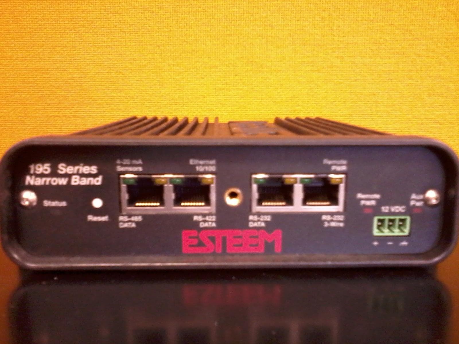
ENPESTEEM195H
Aug 12, 2014217-220MHz VHF Telemetry Modem
Equipment Class
TNB - Licensed Non-Broadcast Station Transmitter
ENPESTEEM195C
Dec 19, 2013450-470MHz Narrow-band UHF modem
Equipment Class
TNB - Licensed Non-Broadcast Station Transmitter
ENPESTEEM210M
Sep 05, 2013Data radio modem
Equipment Class
TNB - Licensed Non-Broadcast Station Transmitter
ENPESTEEM210C
Mar 10, 2013Data radio modem
Equipment Class
TNB - Licensed Non-Broadcast Station Transmitter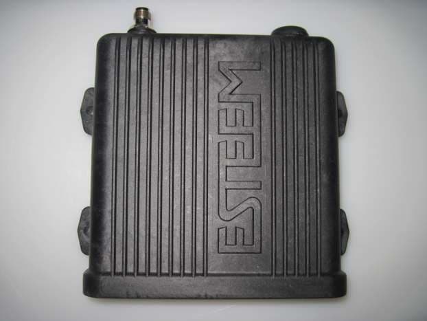
ENPESTEEM195EA
Feb 12, 2012Wireless LAN transceiver
Equipment Class
DTS - Digital Transmission System