F530010BASETETHERNET HUB
Tyco Safety Products Canada Ltd.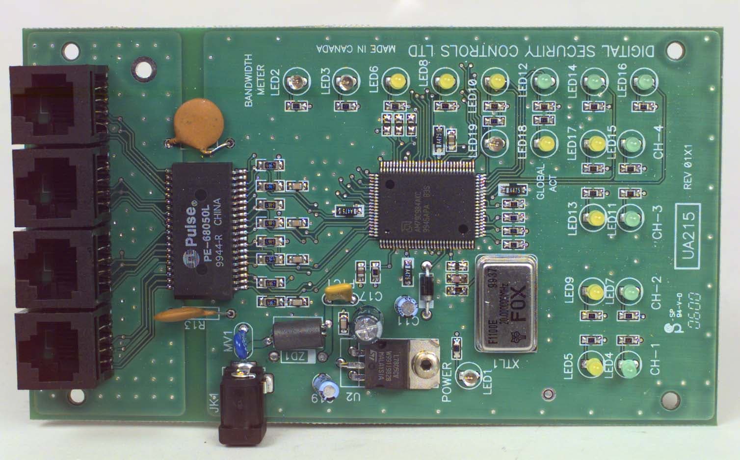
Click to zoom
Application Details
- Equipment Class
- JBP - Part 15 Class B Computing Device Peripheral
- Date of Grant
- Jun 22, 2000
- Application Purpose
- Original Equipment
- Date of Application
- Jun 11, 2000
- Equipment Note
- ETHERNET HUB
- Country
- Canada
Documents & Files
Document Text
Text extracted from the exhibit documents filed with the FCC. Open a document above to read the original.
Users Manual
Four Channel 10BaseT Ethernet Hub Installation Instructions Brian Wa uc hope 04/25/00 Spe cificatio ns: ! Compliant with IEEE 802.3 specifications. ! Standby current draw = 96mA ! Maximum current draw = 330mA ! Input voltage range = 8 to 15VDC ! Ma xi mum Ba ndw idth = 10 MB/s Mounting Instructions: 1. Locate a suitable mounting location for the Ethernet Hub module inside the cabinet. 2. Align the two mounting tabs with the holes located in the bottom of the wire raceway and insert. 3. Snap the module into place by pushing the opposite side towards the back of the cabinet. Wiring Instructions: 1. Home-run CAT-5 cable to each desired location throughout the dwelling and route into the cabinet. 2. Connect each CAT-5 drop to a port on the Ethernet Hub marked ‘Port 1’, ‘Port 2’, ‘Port 3’ or ‘Port 4’. 3. Locate a suitable 110VAC receptacle for placement of the wall-mount transformer. 4. Route the output cord from the wall-mount transformer (supplied) into the cabinet and plug into the Ethernet Hub ‘PWR-IN’ jack. 5. Apply power to the wall-mount transformer. Important: All requirements for Installation of CAT 5 should be met for proper operation of connected equipment. Some require ments of CAT-5: Do not strip sheathing of cable more then required for proper termination. Do not kink or knot cable. Do not crush cable with cable ties. Do not bend cable at right angles or sharp bends. All cable bends should have a minimum of a 2" radius. NOTE: A minimum of two and a maximum of four computers or peripherals must be connected for proper operation of the hub. The network connections can be made on any available port on the hub and are not restricted to certain ports. Also note that the computers and/or peripherals must be configured properly for peak performance of the hub. Please consult the manual supplied with your operating system software. CabinetModule Tabs LED Indication: LabelColorFunction PowerRedPower presence CH-1GreenLink Status YellowCollision Detect CH-2GreenLink Status YellowCollision Detect CH-3GreenLink Status YellowCollision Detect CH-4GreenLink Status YellowCollision Detect Global ActRedCollision YellowCarrier Sense Bandwidth MeterRed>80% Bandwidth Utilization Red>64% Bandwidth Utilization Yellow>32% Bandwidth Utilization Yellow>16% Bandwidth Utilization Yellow>8% Bandwidth Utilization Green>4% Bandwidth Utilization Green>2% Bandwidth Utilization Green>1% Bandwidth Utilization Typical Installation: Computer or Networkable Peripheral Computer or Networkable Peripheral CAT 5 Cable Computer or Networkable Peripheral Computer or Networkable Peripheral CAT 5 Cable 9V DC 500mA Adapter
Attestation Statements
May 31, 2000 Office of Engineering & Technology Federal Communications Commission Washington, D.C. 20554 Subject:Request for continuous confidentiality of technical information per sections 0.459 and 0.457 (d) (2) ( I) of CFR 47. FCC ID:F530010BASET Dear Sir or Madam: Digital Security Controls Canada Ltd. is hereby filing this request for continuous confidentiality of the specified items submitted with the application for certification ( Form731 ) with proposed identifier F530010BASET. The technical documentation for which continuous confidentiality is sought is: (1) Schematic diagrams: (2) Circuit/Technical description This technical documentation is a part of the material supporting the Form 731 application for certification, which this request for confidentiality accompanies. The schematic diagrams disclose proprietary information and technical data which Digital Security Controls Ltd. would guard from its competitors and would not make available to the public. This proprietary information constitutes a trade secret and is not a part of the product documentation that would be made available to the customers of Digital Security Controls Ltd. It would be potentially injurious to Digital Security Controls Ltd. and to its investment in the development of this innovative proprietary product to make available for public disclosure the trade secret technical information specified in this request. If there are any questions about this request for continuous confidentiality regarding trade secrets and proprietary information embodied in the technical documentation filed in support of this Form 731 application, then please contact me via our toll-free telephone number. Yours truly, Kevin Harris Approval Services Manager 905-760-3000 Ext. 2378 Email: [email protected]
ID Label/Location Info
Digital Security Controls Ltd.ISO9001 Registered3301 Langstaff Road, ConcordOntario, Canada L4K 4L2Phone: 905-760-3000Toll Free: 1-888-888-7838Fax: 905-760-3030 ® DASHED LINE INDICATESCUT EDGE OF LABELLABEL TO BE PRINTEDON SELF-ADHESIVE MATERIALLABEL SHOWN 250% ACTUAL SIZE 32 mm 9.7 mm FCC Labeling for HS-NH400 4-Port 10BaseT Ethernet Hub File: [hs-nh400 _fcc_lb_18005808.cdr] May 24, 2000 Top of the PCB showing placement of label (Actual size) Model: HS-NH400 Digital Security Controls Ltd. MADE IN CANADA 18005808 R001 FCC ID: F530010BASETThis device complies with Part 15 of the FCC Rules. Operation issubject to the following two conditions: (1) This device may notcause harmful interference, and (2) this device must accept anyinterference received, including interference that may cause un-desired operation.
Test Report
Master: ktlPT15BBC Date: March 21, 2000 KTL Test Report:0R02503 Applicant:Digital Security Controls Ltd. 3301 Langstaff Road Vaughn, Ontario L4K 4L2 Equipment Under Test:Ethernet Hub (E.U.T.) In Accordance With:FCC Part 15, Subpart B Class B Certification Tested By:KTL Ottawa Inc. 3325 River Road, R.R. 5 Ottawa, Ontario K1V 1H2 Authorized By: K. Colborne, RF Group Manager Date: Total Number of Pages:27 KTL Ottawa FCC PART 15, SUBPART B CLASS B CERTIFICATION PROJECT NO.: 0R02503 EQUIPMENT: Ethernet Hub Page 2 of 27 Table Of Contents Section 1. Summary of Test Results.......................................................................................... 3 Section 2. Equipment Under Test (E.U.T.) .............................................................................. 6 Section 3. Equipment Configuration ........................................................................................ 9 Section 4. Conducted Emissions.............................................................................................. 11 Section 5. Radiated Emissions................................................................................................. 16 Section 6. Sample Calculations ............................................................................................... 24 Section 7. Block Diagrams.......................................................................................................25 Section 8. Test Equipment List ............................................................................................... 27 KTL Ottawa FCC PART 15, SUBPART B CLASS B CERTIFICATION PROJECT NO.: 0R02503 EQUIPMENT: Ethernet Hub Page 3 of 27 Section 1.Summary of Test Results General: All measurements are traceable to national standards. These tests were conducted on a sample of the equipment for the purpose of demonstrating compliance with FCC Part 15, Subpart B for Class B Digital Devices. These tests were conducted using measurement procedures of ANSI C63.4-1992. The equipment was tested for conducted emissions from 0.45 MHz to 30 MHz using a 50 microhenry line impedance stabilization network (L.I.S.N.) as described in ANSI C63.4-1992. Peripheral equipment was also operated through a 50 microhenry L.I.S.N. The equipment was tested for radiated emissions from 30 MHz to 1000 MHz with extension to the 10 th harmonic of any fundamental clock frequency in accordance with the requirements of FCC Part 15, Subpart B. Frequencies were initially identified in a large shielded room. Amplitude measurements were made on an outdoor Open Area Test Site. Details of the outdoor site are on file with the FCC. Abstract: Name Of TestPara. No.Results Conducted Emissions15.107Complies Radiated Emissions15.109Complies THIS REPORT APPLIES ONLY TO THE ITEM(S) TESTED. THE FOLLOWING DEVIATIONS FROM, ADDITIONS TO, OR EXCLUSIONS FROM THE TEST SPECIFICATIONS HAVE BEEN MADE. None NVLAP Lab Code: 100351-0 Test Performed By: ________________________________Date: __________________ Chris Maidens, Test Technician KTL Ottawa Inc. authorizes the above named company to reproduce this report provided it is reproduced in its entirety and for use by the company’s employees only. Any us e whic h a third p a rty ma k e s o f this re p o rt, o r a ny re lia nc e o n o r d e c is io ns to b e ma d e b a s e d o n it, a re the re s p o ns ib ility of such third parties. KTL Ottawa Inc. accepts no responsibility fo r d a ma ge s , if a ny, s uffe re d b y a ny third p a rty a s a re s ult o f d e c is io ns ma d e o r a c tio ns b a s e d o n this re p o rt. This report applies only to the items tested. KTL Ottawa FCC PART 15, SUBPART B CLASS B CERTIFICATION PROJECT NO.: 0R02503 EQUIPMENT: Ethernet Hub Page 4 of 27 Measurement Uncertainty Accuracy of Measurement The measurement uncertainty was calculated using the methods described in NAMAS document NIS81 May 1994, with the confidence level of 95%. Radiated Measurements OATS #1 (A) 3 meter [UN9902B] ContributionDistributionUncertainty (+/-) Field Strength VariationRandom 0.2089 dB μ V^2 Measurement EquipmentNormal 0.3275 dB μ V^2 Measurement EquipmentRectangular 0.4167 dB μ V^2 Total Combined Uncertainty 0.9762 dB μ V^2 Expanded Uncertainty @ 95% Confidence = ± ±± ± 2.0013 dB μ μμ μ V OATS #1 (B) 10 meter [UN9906B] ContributionDistributionUncertainty (+/-) Field Strength VariationRandom 0.1388 dB μ V^2 Measurement EquipmentNormal 0.3275 dB μ V^2 Measurement EquipmentRectangular 0.4167 dB μ V^2 Total Combined Uncertainty 0.9694 dB μ V^2 Expanded Uncertainty @ 95% Confidence = ± ±± ± 1.926 dB μ μμ μ V OATS #2 (B) 3 meter [UN9912B] ContributionDistributionUncertainty (+/-) Field Strength VariationRandom 0.4516 dB μ V^2 Measurement EquipmentNormal 0.3275 dB μ V^2 Measurement EquipmentRectangular 0.4167 dB μ V^2 Total Combined Uncertainty 1.0935 dB μ V^2 Expanded Uncertainty @ 95% Confidence = ± ±± ± 2.2417 dB μ μμ μ V KTL Ottawa FCC PART 15, SUBPART B CLASS B CERTIFICATION PROJECT NO.: 0R02503 EQUIPMENT: Ethernet Hub Page 5 of 27 Radiated Measurements, continued OATS #2 (C) 10 meter [UN9917B] ContributionDistributionUncertainty (+/-) Field Strength VariationRandom 0.1211 dB μ V^2 Measurement EquipmentNormal 0.3275 dB μ V^2 Measurement EquipmentRectangular 0.4167 dB μ V^2 Total Combined Uncertainty 0.9302 dB μ V^2 Expanded Uncertainty @ 95% Confidence = ± ±± ± 1.9069 dB μ μμ μ V Conducted Measurements Shielded Room #1 [UN9920] ContributionDistributionUncertainty (+/-) Amplitude VariationRandom 0.0400 dB μ V^2 Measurement EquipmentNormal 0.7500 dB μ V^2 Measurement EquipmentRectangular 0.2500 dB μ V^2 Total Combined Uncertainty 1.0198 dB μ V^2 Expanded Uncertainty @ 95% Confidence = ± ±± ± 2.0396 dB μ μμ μ V KTL Ottawa FCC PART 15, SUBPART B CLASS B CERTIFICATION PROJECT NO.: 0R02503 EQUIPMENT: Ethernet Hub Page 6 of 27 Section 2.Equipment Under Test (E.U.T.) Brand Name:Ethernet Hub Manufacturer:Digital Security Controls Ltd. Model No.:UA215 Serial No.:None Date Received In Laborat…
Text truncated - open the document above for the full version.
Contact Information
Applicant
Dan Nita(Approvals Manager)
Technical Contact
Non-Technical Contact
KTL OTTAWA INC.RUBY C DULMAGE
[email protected]800-563-6336
Test Firm
Nemko Canada Inc.Stuart Beck
Technical Specifications
| # | Rule Parts | Frequency Range | Power Output |
|---|---|---|---|
| 1 | 15B | - | - |
Other Applications from Tyco Safety Products Canada Ltd.

F53252RFLOCK
Jun 05, 2026IQ Lock-PGP, IQ Lock Touch-PGP
Equipment Class
DTS - Digital Transmission System
F5325PGPDC9
Apr 27, 2026PowerG wireless transceiver module
Equipment Class
DSS - Part 15 Spread Spectrum Transmitter
F5325LC203424
Dec 17, 2025Dual Technology Motion Sensor
Equipment Class
FDS - Part 15 Field Disturbance SensorF5324PGPIO9
Dec 04, 2024Wireless Input / Output (I/O) w/wo contact
Equipment Class
DSS - Part 15 Spread Spectrum Transmitter
F5323PGP9934P
Jan 16, 2024Wireless Motion detector with integrated camera
Equipment Class
DSS - Part 15 Spread Spectrum Transmitter