F5325PGPDC9PowerG wireless transceiver module
Tyco Safety Products Canada Ltd.
Click to zoom
Application Details
- Equipment Class
- DSS - Part 15 Spread Spectrum Transmitter
- Date of Grant
- Apr 27, 2026
- Application Purpose
- Original Equipment
- Equipment Note
- PowerG wireless transceiver module
- Frequency Range
- 912.75000000 - 919.10600000
- Country
- Canada
Documents & Files
Document Text
Text extracted from the exhibit documents filed with the FCC. Open a document above to read the original.
Users Manual
© 2025 Johnson Controls. All rights reserved. PowerSeries Neo 5 Introduction The PGPDCx is a Wireless Alarm Transceiver module that adds wireless capability to the PowerSeries Neo 5 alarm controller models HS2128R, HS2064R, HS2032R or HS2016R. The module is enabled with two-way communication with frequency hopping to increase reliability. Installing the PGPDCx This procedure involves connecting the pin header on the HS2xxxR PCB with the corresponding Power G connector header on the PGPDCx PCB. To install the PGPDCx complete the following steps. Note: Before installing the PGPDCx, ensure the PGPDCx PCB is facing upward. 1. Ensure the PGPDCx PCB is facing upward. 2. Align the PowerG connector header (Con 3) on the back of PGPDCx PCB with the pin header on the HS2xxxR PCB (Con 3) as shown. 3. Firmly press down on the PGPDCx PCB to ensure a good connection to the HS2xxxR pin header. Figure 1: Installing the PGPDCx Table 1: Callout Description 1PGPDCx PowerG Connector 2HS2xxxR PowerG Pin Header Programming the PGPDCx Refer to the PGPHost manual for programming and compatible PowerG initiating devices. © 2025 Johnson Controls. All rights reserved. PGPDCx specifications Table 2: Specifications ItemDescription Frequency bands912.75 to 919.106 MHz, 868.4 to 869.85MHz or 433.22 to 434.64MHz MCU clock frequency32.8kHz RF transceiver frequency48MHz Communication protocolPower G Power/Current draw 55mA Operating temperature 0 ºC (32 °F) to 49 ºC (120 °F) Relative humidity Up to 93% non-condensing Dimensions (L×W) 66mm ×66mm Antenna typeHelical, soldered to the PCB, two used (one vertical and one horizontal) Antenna 0 gain0.8dBi Antenna 1 gain 2.89dBi Note: The x next to the model name refers to the operating frequency, 4 refers to 433 MHz, 8 refers to 868 MHz and 9 refers to 915 MHz PGPDC9 FCC ISED Compliance and RF Exposure Statements Refer to the PGPHost manual for programming and compatible PowerG initiating devices. FCC-ISED Canada Compliance Statement CAN ICES-3 (B) / NMB-3 (B) IMPORTANT: Changes or modifications not expressly approved by Tyco Security Products Canada Ltd. could void the user’s authority to operate the equipment. CAUTION! This equipment complies with radiation exposure limits set forth for uncontrolled environment. The antenna(s) used for these transmitters must be installed to provide a separation distance of at least 20 cm from all persons and must not be collocated or operating in conjunction with any other antenna or transmitter. This device complies with Part 15 of the FCC Rules. Operation is subject to the following two conditions: (1) this device may not cause harmful interference, and (2) this device must accept any interference received, including interference that may cause undesired operation. This equipment has been tested and found to comply with the limits for a Class B digital device, pursuant to part 15 of the FCC Rules. These limits are designed to provide reasonable protection against harmful interference in a residential installation. This equipment generates, uses and can radiate radio frequency energy and, if not installed and used in accordance with the instructions, may cause harmful interference to radio communications. However, there is no guarantee that interference will not occur in a particular installation. If this equipment does cause harmful interference to radio or television reception, which can be determined by turning the equipment o and on, the user is encouraged to try to correct the interference by one or more of the following measures: Reorient or relocate the receiving antenna. Increase the separation between the equipment and receiver. Connect the equipment into an outlet on a circuit dierent from that to which the receiver is connected. Consult the dealer or an experienced radio/TV technician for help. Déclaration d'exposition aux radiations: Cet équipement est conforme aux limites d'exposition aux rayonnements ISED Canada établies pour un environnement non contrôlé. Cet équipement doit être installé et utilisé avec un minimum de 20 cm de distance entre la source de rayonnement et votre corps. Le présent appareil est conforme aux CNR d'Industrie Canada applicables aux appareils radio exempts de licence. L'exploitation est autorisée aux deux conditions suivantes: 1. l'appareil ne doit pas produire de brouillage, et 2. l'utlisateur de l'appareil doit accepter tout brouillage radioélectrique subi, même si le brouillage est susceptible d'en compromettre le fonctionnement. Cet appareil et son antenne ne doivent pas être situés ou fonctionner en conjonction avec une autre antenne ou un autre émetteur, exception faites des radios intégrées qui ont été testées. © 2025 Johnson Controls. All rights reserved. Integration Instructions Integration instructions for host device manufacturers can be found below and are compliant with the KDB 996369 D03 List of applicable FCC rules This Limited Modular Approval device complies with FCC 15.247 rule and RSS-247 requirements. The host device manufacturer is responsible for compliance with any other FCC/ISED rules that apply to the host not covered by the modular transmitter certification. Specific operational use conditions This module cannot be tested stand alone. This Module is intended to be only used in devices designed and sold by Tyco Safety Products Canada. Limited module procedures This Limited Modular Approval transmitter does not have a RF shield over the transmitter portion, and the transmitter is not tested in stand-alone configuration. This Module is approved for use in hosts HS218R, HS2064R, HS2032R or HS2016R. In case, where the module will be integrated in other non-identical hosts in the future, Tyco Safety Products Canada will expand the LMA to include the new hosts after an appropriate assessment to the FCC/ISED rules through a Class II permissive change. Trace antenna designs Not applicable RF exposure considerations The module is only authorized for mobile RF exposure use conditio…
Text truncated - open the document above for the full version.
Attestation Statements
Tyco Safety Products Canada Ltd. 3301 Langstaff Road Concord, Ontario, Canada L4K 4L2 Tele: 1-647-480-0200 https://www.tycosafetyproducts.com October 29, 2025 Nemko North America, Inc. 303 River Road Ottawa ON K1V 1H2 Canada ATTN.: Reviewing Engineer Subject: Covered Equipment Certification Attestation Letter Applicant: Tyco Safety Products Canada Ltd. FCC ID: F5325PGPDC9 The applicant certifies that the equipment for which authorization is sought is not “covered” equipment prohibited from receiving an equipment authorization pursuant to section §2.903 of the FCC rules. This includes certifying that the equipment for which authorization is sought does not include cybersecurity or anti-virus software produced or provided by Kaspersky Lab, Inc. or any of its successors and assignees, including equipment with integrated Kaspersky Lab, Inc. (or any of its successors and assignees) cybersecurity or anti-virus software pursuant to DA-24-886 and KDB 986446 D01 Covered Equipment Guidance section B(2a). Note: If the equipment for which the applicant seeks authorization is produced by any of the entities identified on the current FCC Covered List, the applicant should include an explanation on why the equipment is not “covered” equipment. The applicant certifies that, as of the date of the filing of the application, the applicant is not identified on the Covered List as an entity producing “covered” equipment. Signed: Printed name: Dan Nita Title: Sr. Approvals Manager Company Name: Tyco Safety Products Canada Ltd. Date: October 23, 2025
Attestation Statements
Qolsys Inc. 1919 S Bascom Ave., Suite 600 Campbell, California 95008, USA * the applicant must designate a contact located in the United States for purposes of acting as the applicant’s agent for service of process, regardless of whether the applicant is a domestic or foreign entity. An applicant located in the United States may designate itself as the agent for service of process. ** the agent does not have an FRN because they do no other business with the FCC except for acting as a US agent for service of process, and therefore are not required to have their own FRN. U.S. Agent Designation for Service of Process - Certification Attestation Letter October 29, 2025 Nemko North America, Inc. 303 River Road Ottawa ON K1V 1H2 Canada ATTN.: Reviewing Engineer FCC ID: F5325PGPDC9 Applicant FRN: 0006834485 This letter serves as a formal designation, pursuant to §2.911(d)(7) of the FCC Rules, of the following U.S. Agent* for Service of Process for the equipment under application: U.S. Agent for Service of Process: • Company Name: Qolsys Inc. • Physical U.S. Company Address: 1919 S Bascom Ave., Campbell, CA 95008, USA • Agent Name: Kevin Woodworth • Agent Email Address: [email protected] • Agent FRN**: N/A The above listed designated agent hereby acknowledges and accepts the obligation for service of process on behalf of the applicant signed below. The applicant further acknowledges and accepts its obligation to maintain a U.S. Agent for Service of Process for a minimum period of one year following either: • Permanent termination of all marketing and importation activities within the U.S. for the applicable equipment by the grantee. • The conclusion of any Commission-related administrative or judicial proceeding involving the equipment, whichever occurs later. Qolsys Inc. 1919 S Bascom Ave., Suite 600 Campbell, California 95008, USA * the applicant must designate a contact located in the United States for purposes of acting as the applicant’s agent for service of process, regardless of whether the applicant is a domestic or foreign entity. An applicant located in the United States may designate itself as the agent for service of process. ** the agent does not have an FRN because they do no other business with the FCC except for acting as a US agent for service of process, and therefore are not required to have their own FRN. Applicant Signed: Designated Agent Signed: (Required, if different to Applicant) Signed: Signed: Printed name: Dan Nita Printed name: Kevin Woodworth Title: Sr. Approvals Manager Title: Sr. Director Product & Program Manager Intrusion Company Name: Tyco Safety Products Canada Ltd. Company Name: Qolsys Inc. Date: October 23, 2025 Date: October 23, 2025
Cover Letter(s)
Tyco Safety Products Canada Ltd. 3301 Langstaff Road Concord, Ontario, Canada L4K 4L2 Tele: 1-647-480-0200 https://www.tycosafetyproducts.com Nemko North America, Inc. 303 River Road, Ottawa, Ontario, Canada K1V 1H2 Attn: Director of Certification Appointment of Agent for FCC and ISED Certification Application Dear Director of Certification, This letter formally appoints Spencer Zhong of Nemko Canada, Inc. located at 303 River Road, Ottawa, Ontario, Canada K1V 1H2, as our authorized agent to represent us in the application process for equipment certification. We confirm that the submitted documents accurately depict the device or system seeking certification. Additionally, we guarantee that all units produced, imported, or marketed, as defined by FCC and ISED Canada regulations, will possess a label identical to the one submitted with this application. By signing below, we certify that neither our company nor any party involved in the application is subject to denial of federal benefits, including FCC benefits, as outlined in Section 5301 of the Anti- Drug Abuse Act of 1988 (21 U.S.C. §862) due to a conviction for possession or distribution of a controlled substance. Furthermore, no party involved in the application, as defined in 47 CFR 1.2002 (b), is subject to denial of federal benefits, including FCC benefits. We attest to the truth and accuracy of the information provided to the FCC to the best of our knowledge (47 CFR 2.911 (d)) and acknowledge our responsibilities as a grantee regarding certified equipment (47 CFR 2.909). In instances where our authorized agent signs the application for certification on our behalf, we understand that Nemko North America, Inc. remains solely responsible for adhering to the terms and conditions for certification as specified by Nemko Canada Inc. Sincerely, Dated: October 29, 2025 Agency agreement expiration date: October 23, 2026 *Up to 12 months Signed by: Dan Nita Signature Print name Sr. Approvals Manager Title 416 357 1409 Phone Tyco Safety Products Canada Ltd. 3301 Langstaff Road Concord, Ontario, Canada L4K 4L2 Tele: 1-647-480-0200 https://www.tycosafetyproducts.com On behalf of: Tyco Safety Products Canada Ltd. Company name
Cover Letter(s)
Tyco Safety Products Canada Ltd. 3301 Langstaff Road Concord, Ontario, Canada L4K 4L2 Tele: 1-647-480-0200 https://www.tycosafetyproducts.com Dated: 18 February 2026 Federal Communications Commission Equipment Authorization Branch 7435 Oakland Mills Road Columbia, MD 21046 Request for Limited Modular Approval FCC ID: F5325PGPDC9 The following attestation addresses the requirements to support modular approval: Modular approval requirement Yes (provide brief statement) No * (1) The radio elements must have its own radio frequency circuitry shielded. The physical crystal and tuning capacitor(s) may be located external to the shield, but must be on the module assembly - The module doesn’t contain a metal shield which covers all RF components and circuitry. The module is used within a host enclosure for HS2128R, HS2064R, HS2032R, HS2016R (2) The module must have buffered modulation/data inputs (if provided) to ensure that the device will comply with FCC requirements under conditions of excessive data rates or over-modulation. Data to the modulation circuit is buffered as described in the operational description provided with the application – (3) The module must contain its own power supply regulation on the module. This is intended to ensure that the module will comply with FCC requirements regardless of the design of the power supplying circuitry in the device into which the module is installed. The module contains its own power supply regulation. Please refer to schematic filed with this application – (4) The module must comply with the antenna and transmission system requirements of §§ 15.203, 15.204(b), 15.204(c), 15.212(a), and 2.929(b). The antenna must either be permanently attached or employ a ‘‘unique’’ antenna coupler (at all connections between the module and the antenna, including the cable). The ‘‘professional installation’’ provision of § 15.203 is not applicable to modules but can apply to limited modular approvals under paragraph 15.212(b). 15.212(a)(1)(iv) The module connects to its unique antennas soldered to the PCB – (5) The module must demonstrate compliance in a stand-alone configuration, the module must not be inside another device during testing. This is intended to demonstrate that the module can comply with Part 15 emission limits regardless of the device into which it is eventually installed. No The module was tested within the representative host (Model: HS2128R) as shown in test setup photographs filed with this application (6) The module must be labelled with its permanently affixed FCC ID label, or use an electronic display (See KDB Publication 784748 about labelling requirements) There is a label on the module as shown in the labeling exhibit filed with this application. Host specific labeling instructions are shown in the installation manual filed with this application. _ (7) The module must comply with all specific rule or operating requirements applicable to the transmitter, including all the conditions provided in the integration instructions by the grantee. A copy of these instructions must be included in the application for equipment authorization. The module complies with FCC Part 15C requirements. Instructions to the OEM installer are provided in the installation manual filed with this application – (8) The module must comply with any applicable RF exposure requirements The module meets fixed installations RF exposure requirements as shown in the RF exposure test report filed with this application. – * Please provide a detailed explanation if the answer is “No.” Tyco Safety Products Canada Ltd. 3301 Langstaff Road Concord, Ontario, Canada L4K 4L2 Tele: 1-647-480-0200 https://www.tycosafetyproducts.com Limited Module Description This Limited Modular Approval (LMA) is applied with the understanding that the applicant will demonstrate and will retain control over the final installation of the device, such that compliance of the end product is always assured. The operating condition(s) for the LMA; the module is only approved for use when installed in devices produced by grantee. The PGPDC9 PowerG Alarm Transceiver is used in conjunction with the host alarm panels HS2128R, HS2064R, HS2032R and HS2016R only. All these products are built and maintained using the original design documentation and specifications in a factory that has QMS certified under ISO9001. This ensure that the assembly in which the module will be installed, will be maintained such that full compliance of the end product is always ensured. Sincerely, Signature: Name: Dan Nita Title: Sr. Approvals Manager Company: Tyco Safety Products Canada Ltd. Address: 3301 Langstaff Rd., Concord, ON L4K 4L2 Phone: 416-357-1409 Email: [email protected]
Cover Letter(s)
Tyco Safety Products Canada Ltd. 3301 Langstaff Road Concord, Ontario, Canada L4K 4L2 Tele: 1-647-480-0200 https://www.tycosafetyproducts.com October 29, 2025 Nemko North America, Inc. 303 River Road, Ottawa, Ontario, Canada K1V 1H2 Attn: Director of Certification Request for Confidentiality – FCC FCC ID: F5325PGPDC9 Pursuant to FCC 47 CFR 0.457(d)(1)(ii) and 0.459 and FCC guidance published in KDB 726920, we hereby request confidential treatment of information accompanying this application as outlined below. We request the exhibits selected below as long term confidential (LTC) be withheld from public view permanently: Selection of exhibits for LTC - general Exhibit name ☒ Permanent (Long Term) Block Diagrams ☒ Permanent (Long Term) Operation Description / Theory of Operation ☒ Permanent (Long Term) Parts List & Placement / BOM ☒ Permanent (Long Term) Schematics Our company has spent a substantial effort in developing this product and it is one of the first of its kind in the industry. Having the subject information easily available to "competition" would negate the advantage they have achieved by developing this product. Not protecting the details of the design will result in financial hardship. The above information contains trade secrets and proprietary information not customarily released to the public. The public disclosure of this information might be harmful to the applicant and provide unjustified benefits to its competitors. The Applicant understands that pursuant to Rule 0.457(d)(1)(ii), disclosure of this Application and all accompanying materials will not be made before the date of the Grant for this Application. Sincerely, Signed by: Dan Nita Signature Print name Sr. Approvals Manager Title 416 357 1409 Phone Tyco Safety Products Canada Ltd. Company 3301 Langstaff Rd., Concord ON L4K 4L2 Canada Address
External Photos
External Photographs Exhibit Model Number: PGPDC9 FCC ID: F5325PGPDC9 IC: 160A-PGPDC9 Applicant: Tyco Safety Products Canada Ltd. Date: October 30, 2025 Purpose This exhibit provides clear and detailed external photographs of the subject module, as required under FCC §2.1033(b)(7) and ISED RSS-GEN Section 3.2(e). Notes (if applicable) • All photos are representative of the production unit. • No photos have been digitally altered except for cropping or brightness adjustments to improve visibility. 1. Overview of Main PCB (Component Side) 2. Overview of Main PCB (Solder Side)
ID Label/Location Info
18011472R001 Tyco Safety Products Canada Ltd. MADE IN XXXX YYY M/N: PGPDC9 FIRE ALARM AND SECURITY SUBASSEMBLY XXXX is a placeholder only. Please replace “XXXX” with the country of origin and “YYY” with the UL factory ID if applicable. Delete “YYY” is there is no UL factory ID. November 5, 2025 18011472R001 PGPDC9 UL PCB Label Colour: Pantone Process Black Material: White UL approved self-adhesive Mylar type material Lamination: Top lamination (e.g. 1F9, or equivalent) Adhesive: Permanent adhesive backed with protective liner (e.g. 60# Semigloss Tire-III / 40# Liner Code: B37, or equivalent) Cutting: Tolerance +/- 0.25 mm (0.010”) Dashed line indicates cutting - will not print Rounded corner radius = 1.0 mm (0.04”) NOTES: 1. All items must be RoHS compliant. 2. Markings on label must be PERMANENT. 3. Indelible Ink. 4. Non-conductive inks must be used. 5. Non-conductive label adhesive shall be used ONLY. N OTES: 1. All UL and ULC Labels shall be printed on UL approved material. The first time the label is ordered, the artwork must be sent to UL Label Center [email: [email protected], fax: (847)509-6201] for approval. 2. All UL and ULC Labels shall be printed by a UL Listed printing facility. Digital Security Controls 3301 Langstaff Road Concord, Ontario Canada L4K 4L2 Tele: 905 760 3000 Toll Free: 888 888 7838 Fax: 905-760-3020 22.6 mm 24 mm Res Fire/Burg, Com Burg PowerG Wireless Transceiver FCC ID: F5325PGPDC9; IC:160A-PGPDC9 CAN ICES-3 (B) / NMB-3 (B) Label Placement Label placement on back of PCB shown
ID Label/Location Info
February 17, 2026 18011473R001 PGPDC9 (FCC/IC) Product Enclosure Label Colour: Pantone Process Black Material: White UL approved self-adhesive Mylar type material Lamination: Top lamination (e.g. 1F9, or equivalent) Adhesive: Permanent adhesive backed with protective liner (e.g. 60# Semigloss Tire-III / 40# Liner Code: B37, or equivalent) Cutting: Tolerance +/- 0.25 mm (0.010”) Dashed line indicates cutting - will not print Rounded corner radius = 1.0 mm (0.04”) NOTES: 1. All items must be RoHS compliant. 2. Markings on label must be PERMANENT. 3. Indelible Ink. 4. Non-conductive inks must be used. 5. Non-conductive label adhesive shall be used ONLY. N OTES: 1. All UL and ULC Labels shall be printed on UL approved material. The first time the label is ordered, the artwork must be sent to UL Label Center [email: [email protected], fax: (847)509-6201] for approval. 2. All UL and ULC Labels shall be printed by a UL Listed printing facility. Digital Security Controls 3301 Langstaff Road Concord, Ontario Canada L4K 4L2 Tele: 905 760 3000 Toll Free: 888 888 7838 Fax: 905-760-3020 18011473R001 Tyco Safety Products Canada Ltd. 22.6 mm 12.5 mm Contains M/N: PGPDC9 with FCC ID: F5325PGPDC9 IC:160A-PGPDC9 Label Placement Bottom of enclosure
Internal Photos
Internal Photographs Exhibit Model Number: PGPDC9 FCC ID: F5325PGPDC9 IC: 160A-PGPDC9 Applicant: Tyco Safety Products Canada Ltd. Date: October 30, 2025 Purpose This exhibit provides clear and detailed internal photographs of the subject device to show the placement and construction of all internal components related to RF circuitry, shielding, antennas, power circuitry, and modular components, as required under FCC §2.1033(b)(7) and ISED RSS-GEN Section 3.2(e). Notes (if applicable) • All photos are representative of the production unit. • No photos have been digitally altered except for cropping or brightness adjustments to improve visibility. 1. Overview of Main PCB (Component Side) 2. Overview of Main PCB (Solder Side)
RF Exposure Info
www.nemko.com Nemko Canada Inc., a testing laboratory, is accredited by ANSI National Accreditation Board (ANAB). The test results included in this report are within the scope of this accreditation. The ANAB symbol is an official symbol of the ANSI National Accreditation Board, used under licence. FCC and ISED RSS-102– MPE Calculation; Date: June 2025 RF Exposure Compliance – MPE Calculation Report C h o o s e S c a n d i n a v i a n t r u s t Applicant information: Tyco Safety Products Canada Ltd. Product information: Model number (HVIN): PGPDC9 Model name (PMN): Wireless Alarm Transceiver Product type: Fixed Device Device category Consumer Device for General Population/Uncontrolled Exposure FCC Identification: FCC ID: F5325PGPDC9 ISED certification number: IC: 160A-PGPDC9 Date of issue: January 6, 2026 Compliance Specifications: FCC 47 CFR Part 1 Subpart I, §§1.1307, 1.1310 FCC 47 CFR Part 2 Subpart J, §§2.1091, 2.1093 FCC KDB 447498 D01 General RF Exposure Guidance v06 FCC KDB 865664 D01 RF Exposure Procedures and Equipment Authorization Policies ISED Canada RSS-102 Issue 6 December 15, 2023 MPE calculation report Product info: FCC ID: F5325PGPDC9 IC: 160A-PGPDC9 Model: PGPDC9 Page 2 of 7 Test locations of Nemko Canada Inc. Ottawa site Montréal site GTA Cambridge site Facility address 303 River Road Ottawa, Ontario Canada K1V 1H2 Tel: +1 613 737 9680 Fax: +1 613 737 9691 292 Labrosse Avenue Pointe-Claire, Québec Canada H9R 5L8 Tel: +1 514 694 2684 Fax: +1 514 694 3528 1-130 Saltsman Drive Cambridge, Ontario Canada N3E 0B2 Tel: +1 519 650 4811 Test site identifier - FCC CA2040 CA2041 CA0101 Test site identifier – ISED Canada 2040A-4 2040G-5 24676 ANAB File Number AT-3195 AT-3193 AT-3194 Andrey Adelberg Senior EMC/Wireless Specialist Prepared by Signature Limits of responsibility The results presented in this report apply solely to the specific device model tested and are valid only for the operating conditions and installation requirements specified herein. Testing was conducted in accordance with ISO/IEC 17025:2017 requirements, and all results fall within the scope of Nemko Canada's accreditation. This MPE evaluation is based on the maximum power levels and operating conditions specified. Any modifications to the device hardware, software, or installation that could affect RF output power or antenna characteristics may invalidate this compliance demonstration. Copyright notification This report may be reproduced by the applicant in its entirety for regulatory submission and internal use. Any use of this report by third parties, including reliance on its contents or decisions made based on it, is solely at the risk of those third parties. Nemko Canada Inc. assumes no responsibility for any damages incurred by third parties as a result of actions taken based on this report. © Nemko Canada Inc. All rights reserved. MPE calculation report Product info: FCC ID: F5325PGPDC9 IC: 160A-PGPDC9 Model: PGPDC9 Page 3 of 7 1. Executive Summary This report presents the Maximum Permissible Exposure (MPE) analysis for [Product Name] to demonstrate compliance with FCC and ISED RF exposure requirements. The evaluation considers both single transmitter operation and simultaneous multi-transmitter scenarios where applicable. 2. Key Findings Compliance status Complies Critical separation distances 20 cm Special conditions or limitations N/A MPE calculation report Product info: FCC ID: F5325PGPDC9 IC: 160A-PGPDC9 Model: PGPDC9 Page 4 of 7 MPE calculations for stand-alone transmission Device Classification Requirements Portable Device Definition (§2.1093) Devices designed for use by a person where the radiating structure is within 20 cm of the user's body require SAR evaluation rather than MPE calculation. Mobile Device Definition Devices installed in vehicles or with permanently installed antennas may use MPE calculations if minimum separation distances can be established. Fixed/Base Station Definition Stationary transmitters with controlled access to antenna locations may use MPE calculations for both occupational and general population exposure scenarios. 3. References, definitions and limits for FCC FCC §2.1091(d) (2) For operations within the frequency range of 300 kHz and 6 GHz (inclusive), the limits for maximum permissible exposure (MPE), derived from whole-body SAR limits and listed in Table 1 in paragraph (e)(1) of this section, may be used instead of whole-body SAR limits as set forth in paragraphs (a) through (c) of this section to evaluate the environmental impact of human exposure to RF radiation as specified in §1.1307(b) of this part, except for portable devices as defined in §2.1093 of this chapter as these evaluations shall be performed according to the SAR provisions in §2.1093. Table 1: §1.1310(e)(1)—Power Density Limits for Maximum Permissible Exposure (MPE) Frequency range (MHz) Power density (mW/cm 2 ) Averaging time (minutes) (i) Limits for Occupational/Controlled Exposure 0.3–3.0 *(100) ≤6 3.0–30 *(900 / f 2 ) <6 30–300 1.0 <6 300–1500 f / 300 <6 1500–100000 5 <6 (ii) Limits for General Population/Uncontrolled Exposure 0.3–1.34 *(100) <30 1.34–30 *(180 / f 2 ) <30 30–300 0.2 <30 300–1500 f / 1500 <30 1500–100000 1.0 <30 Notes: f = frequency in MHz. * = Plane-wave equivalent power density. MPE calculation report Product info: FCC ID: F5325PGPDC9 IC: 160A-PGPDC9 Model: PGPDC9 Page 5 of 7 4. References, definitions and limits for ISED RSS-102 Section 5.3.2 The power density reference levels, and associated reference period for devices employed by the general public (uncontrolled environment) and controlled-use devices (controlled environment) are specified in table below. Note that the power density limits specified in this table apply to whole body exposure conditions. Table 2: RSS-102— Power density limits Frequency range (MHz) Power density (W/m 2 ) Power density (mW/cm 2 ) Reference Period (minutes) Limits for controlled-use devices (controlled environment) 10–20 10 1 6 20–48 44.72…
Text truncated - open the document above for the full version.
Test Report
New Engineering Part Number Form Company Name:Digital Security ControlsIncoming Date:2015/05/06 Delivery Date:2015/05/06Type Of Part:Antenna DSC Part Number:19001253 Distributor Contact:Visonic Phone #:DSC Contact:Shen, Da Part Description 868MHZ COIL ANTENNA SURFACE MOUNTED WITH PLASTIC CAP Phone #:NA Ext.2732 Ext. Certificate Of Compliance:No Approximate Lead Time:NA Cost Per Volume:NA Forecasted Quantity:NA Safety Critical Component:No Manufacturer Specs Attached:No DSC Purchasing Specs Attached:No Release To Production Date:2015/05/06 Processed By:Hyly Date Processed:06/05/2015 10:38:24 AM Affected Products Apollo CO/Smoke Detectors # Of Pages: # Of Colours: PMS Colours: Type Of Paper: Size of Paper: Language: Literature / Marketing Part Number Information RoHS Compliant?Yes Reason For Part Selection: Need coil antenna with plast…
Text truncated - open the document above for the full version.
Contact Information
Applicant
Dan Nita(Approvals Manager)
[email protected]Fax: 1-647-480-0531
Technical Contact
Test Firm
Nemko Canada Inc. (Cambridge)Charles Neal
Technical Specifications
| # | Rule Parts | Frequency Range | Power Output |
|---|---|---|---|
| 1 | 15C | 912.75 MHz - 919.106 MHz | 29.00 mW |
Other Applications from Tyco Safety Products Canada Ltd.

F53252RFLOCK
Jun 05, 2026IQ Lock-PGP, IQ Lock Touch-PGP
Equipment Class
DTS - Digital Transmission System
F5325LC203424
Dec 17, 2025Dual Technology Motion Sensor
Equipment Class
FDS - Part 15 Field Disturbance SensorF5324PGPIO9
Dec 04, 2024Wireless Input / Output (I/O) w/wo contact
Equipment Class
DSS - Part 15 Spread Spectrum Transmitter
F5323PGP9934P
Jan 16, 2024Wireless Motion detector with integrated camera
Equipment Class
DSS - Part 15 Spread Spectrum Transmitter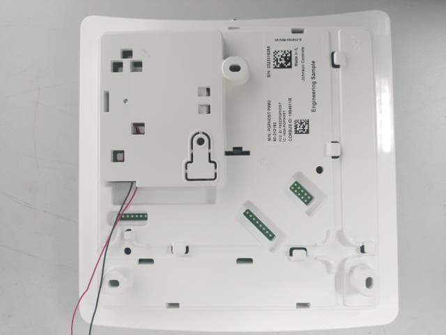
F5323PGPHOST
Dec 05, 2023Wireless Transceiver
Equipment Class
DSS - Part 15 Spread Spectrum Transmitter