F53005132WIRELESS RECEIVER
Tyco Safety Products Canada Ltd.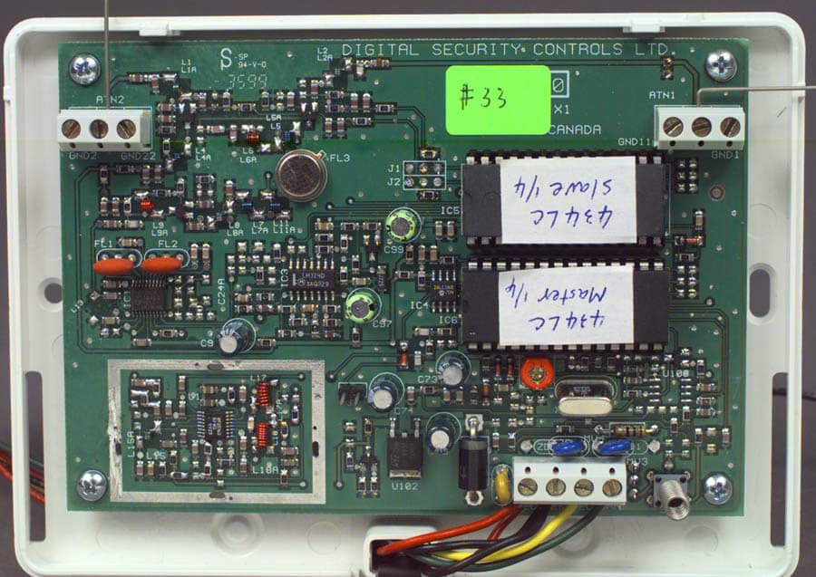
Click to zoom
Application Details
- Equipment Class
- CYY - Communications Receiver used w/Pt 15 Transmitter
- Date of Grant
- Jun 03, 2001
- Application Purpose
- Original Equipment
- Date of Application
- Feb 02, 2000
- Equipment Note
- WIRELESS RECEIVER
- Frequency Range
- 433.92000000 - 433.92000000
- Country
- Canada
Documents & Files
Document Text
Text extracted from the exhibit documents filed with the FCC. Open a document above to read the original.
Users Manual
Installation Manual PC5132-433 Version 3.12 • W A R N I N G • This manual contains information on limitations regarding product use and function and information on the limitations as to liability of the manufacturer. Please see page ii for a description of newPlease see page ii for a description of new Please see page ii for a description of newPlease see page ii for a description of new Please see page ii for a description of new features for the PC5132-433 v3.12.features for the PC5132-433 v3.12. features for the PC5132-433 v3.12.features for the PC5132-433 v3.12. features for the PC5132-433 v3.12. WARNING Please Read Carefully Note to Installers This warning contains vital information. As the only individual in contact with system users, it is your responsibility to bring each item in this warning to the attention of the users of this system. System Failures This system has been carefully designed to be as effective as possible. There are circumstances, however, involving f ire, bur- glary, or other types of emergencies where it may not provide protection. Any alarm system of any type may be compromised deliberately or may fail to operate as expected for a variety of reasons. Some but not all of these reasons may be: nn nn n Inadequate Installation A security system must be installed properly in order to provide adequate protection. Every installation should be evaluated by a security professional to ensure that all access points and areas are covered. Locks and latches on windows and doors must be secure and operate as intended. Windows, doors, walls, ceilings and other building materials must be of sufficient strength and construction to provide the level of protection expected. A re- evaluation must be done during and after any construction activ- ity. An evaluation by the fire and/or police department is highly recommended if this service is available. nn nn n Criminal Knowledge This system contains security features which were known to be effective at the time of manufacture. It is possible for persons with criminal intent to develop techniques which reduce the ef- fectiveness of these features. It is important that a security sys- tem be reviewed periodically to ensure that its features remain effective and that it be updated or replaced if it is found that it does not provide the protection expected. nn nn n Access by Intruders Intruders may enter through an unprotected access point, cir- cumvent a sensing device, evade detection by moving through an area of insufficient coverage, disconnect a warning device, or interfere with or prevent the proper operation of the system. nn nn n Power Failure Control units, intrusion detectors, smoke detectors and many other security devices require an adequate power supply for proper operation. If a device operates from batteries, it is possible for the batteries to fail. Even if the batteries have not failed, they must be charged, in good condition and installed correctly. If a device operates only by AC power, any interruption, however brief, will render that device inoperative while it does not have power. Power interruptions of any length are often accompanied by voltage fluctuations which may damage electronic equipment such as a security system. After a power interruption has oc- curred, immediately conduct a complete system test to ensure that the system operates as intended. nn nn n Failure of Replaceable Batteries This system’s wireless transmitters have been designed to pro- vide several years of battery life under normal conditions. The expected battery life is a function of the device environment, usage and type. Ambient conditions such as high humidity, high or low temperatures, or large temperature fluctuations may re- duce the expected battery life. While each transmitting device has a low battery monitor which identifies when the batteries need to be replaced, this monitor may fail to operate as expected. Regular testing and maintenance will keep the system in good operating condition. nn nn n Compromise of Radio Frequency (Wireless) Devices Signals may not reach the receiver under all circumstances which could include metal objects placed on or near the radio path or deliberate jamming or other inadvertent radio signal interference. nn nn n System Users A user may not be able to operate a panic or emergency switch possibly due to permanent or temporary physical disability, in- ability to reach the device in time, or unfamiliarity with the cor- rect operation. It is important that all system users be trained in the correct operation of the alarm system and that they know how to respond when the system indicates an alarm. nn nn n Smoke Detectors Smoke detectors that are a part of this system may not properly alert occupants of a fire for a number of reasons, some of which follow. The smoke detectors may have been improperly in- stalled or positioned. Smoke may not be able to reach the smoke detectors, such as when the fire is in a chimney, walls or roofs, or on the other side of closed doors. Smoke detectors may not detect smoke from fires on another level of the residence or building. Every f ire is different in the amount of smoke produced and the rate of burning. Smoke detectors cannot sense all types of fires equally well. Smoke detectors may not provide timely warning of fires caused by carelessness or safety hazards such as smoking in bed, violent explosions, escaping gas, improper storage of flammable materials, overloaded electrical circuits, children playing with matches or arson. Even if the smoke detector operates as intended, there may be circumstances when there is insufficient warning to allow all occupants to escape in time to avoid injury or death. nn nn n Motion Detectors Motion detectors can only detect motion within the designated areas as shown in their respective installation instructions. They cannot discriminate between intruders and intended occupants. Motion detectors do not provide volumetric area pro…
Text truncated - open the document above for the full version.
Cover Letter(s)
Offices In Hull (UK), Ottawa (Canada), Dallas (USA) And Arnhem (The Netherlands) February 3, 2000 Federal Communications Commission Equipment Authorization Branch 7435 Oakland Mills Road Columbia, Maryland 21046 USA KTL 3325 River Road RR #5 Ottawa, Ontario Canada K1V 1H2 Tel: 613-737-9680 Fax: 613-737-9691 Toll Free: 1-800-563-6336 Email: [email protected] Internet: www.ktl.com Dear Sir/Madam:Our File Ref. 9R02131 FCC ID: F53005132 Applicant: Digital Security Controls Ltd. Equipment: PC5132-433 Radio Receiver FCC Confirmation no.: EA96695 We have successfully electronically filed all the required documentation for an application for certification in accordance with FCC Part 15 on the above mentioned equipment, February 3, 2000. Enclosed, please find a cheque in the amount of $365.00 US, a copy of FCC Remittance Form 159, a copy of the FCC Form 731 confirmation number and a copy of the list of exhibits. PLEASE NOTE THE CHANGE OF ADDRESS AND CONTACT NAME FOR THIS COMPANY. Digital Security Controls Ltd. 3301 Langstaff Road Vaughan, ON L4K 4L2 Contact: Kevin Harris, Approval Services Manager Tel: 905-760-3000 ext 378 Fax: 905-760-3020 e-mail: [email protected] If you require additional information, please do not hesitate to contact me at 1-800-563-6336 (extension 232). Thank you in advance for your assistance in this matter. Sincerely, Ruby Dulmage Regulatory Submissions Clerk KTL Ottawa Inc. [email protected] Encl.
ID Label/Location Info
Digital Security Controls Ltd.ISO9001 Registered3301 Langstaff Road, ConcordOntario, Canada L4K 4L2Phone: 905-760-3000Toll Free: 1-888-888-7838Fax: 905-760-3030 TM FCC/IC Labeling for PC5132-433 SIDE OF TRANSMITTER UNIT SHOWING PLACEMENT OF LABEL(ACTUAL SIZE) File: [pc5132-433 fcc+ic lb 1800xxxx r001.cdr] January 26, 2000 FCC ID: F53005132 Model: PC5132-433 Digital Security Controls Ltd. This device complies with Part 15 of the FCC Rules. Operation is subject to the following two con-ditions: (1) This device may not cause harmful interference, and (2) this device must accept anyinterference received, including interference that may cause undesired operation.IC: RSS/CNR210 CANADA: 160 XXX XXXX 1800XXXX R001 This Class B digital apparatus meets all requirements of the ICES-003. Cet appareil numériquede la classe B respecte toutes les exigences du ICES-003. MADE IN CANADA DASHED LINE INDICATESCUT EDGE OF LABELLABEL TO BE PRINTEDON SELF-ADHESIVEMATERIALLABEL SHOWN 250% ACTUAL SIZE 44.5 mm 9.5 mm
Test Report
Master: ktlPT15BR Date: October 8, 1999 KTL Test Report:9R02131 Applicant:Digital Security Controls Ltd. 3301 Langstaff Road Concord, Ontario L4K 4L2 Equipment Under Test:PC5132-433 Radio Receiver (E.U.T.) FCC ID:F53005132 In Accordance With:FCC Part 15, Subpart B Radio Receivers Tested By:KTL Ottawa Inc. 3325 River Road, R.R. 5 Ottawa, Ontario K1V 1H2 Authorized By: Russell Grant, Wireless Group Manager Date: Total Number of Pages:11 KTL OttawaFCC PART 15, SUBPART B RADIO RECEIVERS PROJECT NO.: 9R02131 EQUIPMENT: PC5132-433 Radio Receiver FCC ID: F53005132 Page 2 of 11 Table Of Contents Section 1. Summary of Test Results .....................................................................................................3 Section 2. Equipment Under Test (E.U.T.) ..........................................................................................5 Section 3. Radiated Emissions ..............................................................................................................7 Section 4. Block Diagrams...................................................................................................................10 Section 5. Test Equipment List ...........................................................................................................11 KTL OttawaFCC PART 15, SUBPART B RADIO RECEIVERS PROJECT NO.: 9R02131 EQUIPMENT: PC5132-433 Radio Receiver FCC ID: F53005132 Page 3 of 11 Section 1.Summary of Test Results General: All measurements are traceable to national standards. These tests were conducted on a sample of the equipment for the purpose of demonstrating compliance with FCC Part 15, Subpart B. Measurement procedure ANSI C63.4-1992 was used for all tests. Radiated Emissions were measured on an open area test site. New SubmissionProduction Unit Class II Permissive ChangePre-Production Unit CYY Equipment Code THIS TEST REPORT RELATES ONLY TO THE ITEM(S) TESTED. THE FOLLOWING DEVIATIONS FROM, ADDITIONS TO, OR EXCLUSIONS FROM THE TEST SPECIFICATIONS HAVE BEEN MADE. See “ Summary of Test Data”. NVLAP LAB CODE: 100351-0 It is recommended that the margin of compliance be improved to allow for manufacturing tolerances TESTED BY: _____________________________________ DATE: ___________________ Kevin Rose, Test Technician KTL Ottawa Inc. authorizes the above named company to reproduce this report provided it is reproduced in its entirety and for use by the company’s employees only. Any use which a third party makes of this report, or any reliance on or decisions to be made based on it, are the responsibility of such third parties. KTL Ottawa Inc. accepts no responsibility for damages, if any, suffered by any third party as a result of decisions made or actions based on this report. This report applies only to the items tested. KTL OttawaFCC PART 15, SUBPART B RADIO RECEIVERS PROJECT NO.: 9R02131 EQUIPMENT: PC5132-433 Radio Receiver FCC ID: F53005132 Page 4 of 11 Summary Of Test Data Name Of TestPara. No.Results Antenna Conducted Emissions15.111Not Applicable Radiated Emissions15.109Complies Powerline Conducted Emissions15.107Not Applicable Footnotes For N/A’s:This equipment was tested with a permanently attached antenna. This equipment is powered by 12 Vdc. Test Conditions: IndoorTemperature: 20 °C Humidity:20 % OutdoorTemperature: 10 °C Humidity:20 % KTL OttawaFCC PART 15, SUBPART B RADIO RECEIVERS PROJECT NO.: 9R02131 EQUIPMENT: PC5132-433 Radio Receiver FCC ID: F53005132 Page 5 of 11 Section 2.Equipment Under Test (E.U.T.) Manufacturer:Digital Security Controls Ltd. Model No.:PC5132-433 Serial No.:None Date Received In Laboratory: January 17, 2000 KTL Identification No.: Item #2 Equipment Details Frequency Range:433.92 MHz Number of Channels:1 Operating Frequency(ies) of Sample:433.92 MHz Primary Power Requirement:12 Vdc Intermediate Frequency(ies):10.7 MHz KTL OttawaFCC PART 15, SUBPART B RADIO RECEIVERS PROJECT NO.: 9R02131 EQUIPMENT: PC5132-433 Radio Receiver FCC ID: F53005132 Page 6 of 11 Configuration of the Equipment Under Test EUT 12 Vdc Power Supply Antenna 1.5m, 2 Conductor Unshielded Cable KTL OttawaFCC PART 15, SUBPART B RADIO RECEIVERS PROJECT NO.: 9R02131 EQUIPMENT: PC5132-433 Radio Receiver FCC ID: F53005132 Page 7 of 11 Section 3.Radiated Emissions NAME OF TEST: Radiated EmissionsPARA. NO.: 15.109(a) TESTED BY: Kevin RoseDATE: January 19, 2000 Minimum Standard: Frequency(MHz)Field Strength (dBμ μμ μV/m @ 3m) 30 - 8840.0 88 - 21643.5 216 - 96046.0 Above 96054.0 Test Results:Complies. The worst-case emission level is 45.7 dBμV/m @ 3m at 423.21 MHz. This is 0.3 dB below the specification limit. Measurement Data:See attached table. For super-regenerative receivers the receiver is cohered using a signal generator and dipole antenna. Handheld equipment and equipment not designed to be mounted in any fixed orientation, the E.U.T. is tested in three orthogonal axis to obtain worst case results. KTL OttawaFCC PART 15, SUBPART B RADIO RECEIVERS PROJECT NO.: 9R02131 EQUIPMENT: PC5132-433 Radio Receiver FCC ID: F53005132 Page 8 of 11 Test Data - Radiated Emissions Test Distance (meters) : 3 Range: A Tower Receiver: ESVP H.P. 8564E RBW(kHz): 120K 1 MHz Detector: CISPR, Q-PEAK, PEAK Freq. (MHz) Ant. * Pol. (V/H) Ant. HGT. (m) Table (deg.) RCVD Signal (dBμ μμ μV/m) Ant. Factor (dB)** Amp. Gain (dB)*** Duty Cycle (dB) Field Strength (dBμ μμ μV/m) Limit (dBμ μμ μV/m) Margin (dB) 423.21E/D4V20.025.745.746.00.3 423.21E/D4H13.025.738.746.07.3 846.43E/D4V6.834.341.146.04.9 845.43E/D4H6.834.341.146.04.9 1269.65Hrn2V8.028.036.054.018.0 1269.65Hrn2H7.728.035.754.018.3 1692.88Hrn2V23.629.4-46.16.954.047.1 1692.88Hrn2H24.029.4-46.17.354.046.7 39.67B/C2V14.113.027.140.012.9 39.67B/C2H8.613.021.640.018.4 Notes: B/C = Biconical, B/L = Biconilog, L/P = Log-Periodic, H = Horn, D/P = Dipole * Re-measured using dipole antenna. ** Includes cable loss when amplifier is not used. *** Includes cable loss. ( ) Denotes failing emission level. KTL OttawaFCC PART 15, SUBPART B RADIO RECE…
Text truncated - open the document above for the full version.
Contact Information
Applicant
Dan Nita(Approvals Manager)
Technical Contact
Non-Technical Contact
KTL OTTAWA INC.RUBY C DULMAGE
[email protected]613-737-9680
Test Firm
Nemko Canada Inc.Stuart Beck
Technical Specifications
| # | Rule Parts | Frequency Range | Power Output |
|---|---|---|---|
| 1 | 15B | 433.92 MHz - 433.92 MHz | - |
Other Applications from Tyco Safety Products Canada Ltd.

F53252RFLOCK
Jun 05, 2026IQ Lock-PGP, IQ Lock Touch-PGP
Equipment Class
DTS - Digital Transmission System
F5325PGPDC9
Apr 27, 2026PowerG wireless transceiver module
Equipment Class
DSS - Part 15 Spread Spectrum Transmitter
F5325LC203424
Dec 17, 2025Dual Technology Motion Sensor
Equipment Class
FDS - Part 15 Field Disturbance SensorF5324PGPIO9
Dec 04, 2024Wireless Input / Output (I/O) w/wo contact
Equipment Class
DSS - Part 15 Spread Spectrum Transmitter
F5323PGP9934P
Jan 16, 2024Wireless Motion detector with integrated camera
Equipment Class
DSS - Part 15 Spread Spectrum Transmitter